EP0978327A2 - Screening machine - Google Patents
Screening machine Download PDFInfo
- Publication number
- EP0978327A2 EP0978327A2 EP99110456A EP99110456A EP0978327A2 EP 0978327 A2 EP0978327 A2 EP 0978327A2 EP 99110456 A EP99110456 A EP 99110456A EP 99110456 A EP99110456 A EP 99110456A EP 0978327 A2 EP0978327 A2 EP 0978327A2
- Authority
- EP
- European Patent Office
- Prior art keywords
- screening machine
- machine according
- force transmission
- transmission elements
- elements
- Prior art date
- Legal status (The legal status is an assumption and is not a legal conclusion. Google has not performed a legal analysis and makes no representation as to the accuracy of the status listed.)
- Granted
Links
- 238000012216 screening Methods 0.000 title claims abstract description 30
- 230000005540 biological transmission Effects 0.000 claims description 34
- 238000007873 sieving Methods 0.000 description 4
- 238000010276 construction Methods 0.000 description 2
- 230000000630 rising effect Effects 0.000 description 2
- 230000001174 ascending effect Effects 0.000 description 1
- 239000013500 performance material Substances 0.000 description 1
Images


Classifications
-
- B—PERFORMING OPERATIONS; TRANSPORTING
- B07—SEPARATING SOLIDS FROM SOLIDS; SORTING
- B07B—SEPARATING SOLIDS FROM SOLIDS BY SIEVING, SCREENING, SIFTING OR BY USING GAS CURRENTS; SEPARATING BY OTHER DRY METHODS APPLICABLE TO BULK MATERIAL, e.g. LOOSE ARTICLES FIT TO BE HANDLED LIKE BULK MATERIAL
- B07B1/00—Sieving, screening, sifting, or sorting solid materials using networks, gratings, grids, or the like
- B07B1/46—Constructional details of screens in general; Cleaning or heating of screens
- B07B1/48—Stretching devices for screens
- B07B1/485—Devices for alternately stretching and sagging screening surfaces
-
- B—PERFORMING OPERATIONS; TRANSPORTING
- B07—SEPARATING SOLIDS FROM SOLIDS; SORTING
- B07B—SEPARATING SOLIDS FROM SOLIDS BY SIEVING, SCREENING, SIFTING OR BY USING GAS CURRENTS; SEPARATING BY OTHER DRY METHODS APPLICABLE TO BULK MATERIAL, e.g. LOOSE ARTICLES FIT TO BE HANDLED LIKE BULK MATERIAL
- B07B1/00—Sieving, screening, sifting, or sorting solid materials using networks, gratings, grids, or the like
- B07B1/28—Moving screens not otherwise provided for, e.g. swinging, reciprocating, rocking, tilting or wobbling screens
Definitions
- the invention relates to a screening machine with several arranged in parallel next to each other and at intervals Cross members, between which flexible screen coverings are attached and of which every second cross member (first Cross member) relative to the intermediate Cross members (second cross members) around the longitudinal axis and forth are tiltable, with the second intermediate Cross beams opposite to the first cross beams the longitudinal axis can be tilted back and forth around the screen pads to stretch and compress alternately.
- Such a screening machine is from the German one Publication 3823896 known. At this Known screening machine, the cross members through Rocker arm driven. Such a construction is complex and space-consuming.
- the object of the invention is to provide a screening machine improve the type mentioned so that at simple construction and small dimensions low susceptibility to failure and high sieving performance achieved become.
- the tension element is a toothed belt with teeth arranged on both sides and the power transmission elements are gears.
- the traction element is a toothless belt, a band, a rope, a V-belt or a chain.
- the pull and push element is a rack that engages in gears or gear segments.
- a Multi-deck machine in particular a double-deck machine is, whose layers of cross beams by different Pull / push elements or by the same pull / push element are driven.
- the pull / push elements can also be arranged on both sides of the screening machine.
- every second Power transmission element is lower than that intermediate transmission elements, so that the power transmission elements over a smaller or larger angular range are wrapped by the tension element.
- the pull / push elements can be separated in order a machine with different deflections work. As a result, the sieving performance Material flow adjusted. It is also an advantage if that or the tension element (s) of two parallel to each other lying belt is (are).
- the sieving capacity is increased if below Sieve surface negative pressure is present.
- a particularly high sieving performance is achieved if the Cross beams rising in steps or cascades or are staggered.
- the drive is simplified if at least one of the Power transmission elements is driven and on the Pulling or pushing elements the rest Power transmission elements drives.
- the screening machine 1 has several in parallel side by side cross beams 2 arranged at equal intervals, between which flexible screen pads 3 are attached.
- the Crossbeams are rotated by a certain angle twisted here, with every second cross member (first Cross member 2a) in the opposite direction is pivoted as the cross member in between (second cross member 2b).
- first Cross member 2a every second cross member in the opposite direction is pivoted as the cross member in between (second cross member 2b).
- each cross member 2a, 2b power transmission elements 4th in the form of wheels, wheel segments, gears or Gear segments attached by a tension element 5, in particular a strap or a band or through Similar elements are driven, the tension element 5 alternate over the bottom and top of the Elements 4 runs.
- the tension element 5 is at one end driven by a crank gear 6 and the other A spring 7 is attached to the end of the tension element 5 the tension element 5 keeps tension.
- one Pull element can also be a push element 8, in particular in the form of a rack, into the teeth of the power transmission elements 4 intervenes.
- the exemplary embodiment differs from this Fig. 2 in that the pull / push element 5, 8 on one End of a cross member 2 below the element 4 and runs above on the opposite end or with the adjacent crossbeam in reverse Wise.
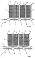
- Fig. 9 is the drive of a double deck screening machine with double racks according to FIG. 7 for each Deck illustrated.
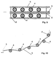
- Fig. 10 shows the drive of a screening machine, the Screen covering is arranged in ascending order.
- the tension element can be a Timing belt with teeth on both sides or a toothless belt, a band, a rope, a V-belt or be a chain, the power transmission element then is designed accordingly.
- the thrust element is preferably a rack with one or both sides Teeth.
- the drive is on one End of the pull or push element shown. It can but also by one of the power transmission elements 4 be driven, which then via the train or Thrust element 5, 8 the remaining force transmission elements 4th drives.
Abstract
Description
Die Erfindung betrifft eine Siebmaschine mit mehreren parallel nebeneinander und in Abständen angeordneten Querträgern, zwischen denen flexible Siebbeläge befestigt sind und von denen jeder zweite Querträger (erste Querträger) relativ zu den dazwischen liegenden Querträgern (zweite Querträger) um die Längsachse hin und her kippbar sind, wobei die dazwischen liegenden zweiten Querträger entgegengesetzt zu den ersten Querträgern um die Längsachse hin und her kippbar sind, um die Siebbeläge abwechselnd zu strecken und zu stauchen.The invention relates to a screening machine with several arranged in parallel next to each other and at intervals Cross members, between which flexible screen coverings are attached and of which every second cross member (first Cross member) relative to the intermediate Cross members (second cross members) around the longitudinal axis and forth are tiltable, with the second intermediate Cross beams opposite to the first cross beams the longitudinal axis can be tilted back and forth around the screen pads to stretch and compress alternately.
Eine solche Siebmaschine ist aus der deutschen Offenlegungsschrift 3823896 bekannt. Bei dieser bekannten Siebmaschine werden die Querträger durch Kipphebel angetrieben. Eine solche Konstruktion ist aufwendig und platzraubend.Such a screening machine is from the German one Publication 3823896 known. At this Known screening machine, the cross members through Rocker arm driven. Such a construction is complex and space-consuming.
Aufgabe der Erfindung ist es, eine Siebmaschine der eingangs genannten Art so zu verbessern, daß bei einfacher Konstruktion und geringen Abmessungen eine geringe Störanfälligkeit und hohe Siebleistungen erreicht werden.The object of the invention is to provide a screening machine improve the type mentioned so that at simple construction and small dimensions low susceptibility to failure and high sieving performance achieved become.
Diese Aufgabe wird erfindungsgemäß dadurch gelöst, daß an den Enden der Querträger Kraftübertragungselemente, insbesondere Räder oder Radsegmente befestigt sind, über die mindestens ein angetriebenes Zugelement und/oder ein Schubelement läuft, das/die bei den ersten Querträgern auf der Unterseite und bei den zweiten Querträgern auf der Oberseite der Kraftübertragungselemente anliegt/anliegen.This object is achieved in that the ends of the cross members power transmission elements, in particular wheels or wheel segments are attached via the at least one driven tension element and / or a Thrust element runs, that of the first cross beams on the underside and on the second cross members the top of the power transmission elements is concerned.
Hierdurch wird ein konstruktiv besonders einfacher Antrieb für Siebmaschinen mit mehreren nebeneinander liegenden Querträgern erreicht. Die Abmessungen, insbesondere in der Höhe sind gering und es werden hohe Siebleistungen erzielt.This makes a particularly simple design Drive for screening machines with several side by side horizontal cross beams reached. The dimensions, are particularly low in height and high Achievements achieved.
Besonders vorteilhaft ist es hierbei, wenn das Zugelement ein Zahnriemen mit beidseitig angeordneten Zähnen ist und die Kraftübertragungselemente Zahnräder sind. Auch kann das Zugelement ein zahnloser Riemen, ein Band, ein Seil, ein Keilriemen oder eine Kette sein. Eine ähnlich vorteilhafte Ausführung wird alternativ dann geschaffen, wenn das Zug- und Schubelement eine Zahnstange ist, die in Zahnrädern oder Zahnradsegmenten eingreift. It is particularly advantageous here if the tension element is a toothed belt with teeth arranged on both sides and the power transmission elements are gears. Can too the traction element is a toothless belt, a band, a rope, a V-belt or a chain. A similar one advantageous embodiment is alternatively created if the pull and push element is a rack that engages in gears or gear segments.
Vorzugsweise wird vorgeschlagen, daß sie eine Mehrdeckmaschine, insbesondere eine Doppeldeckmaschine ist, deren Lagen von Querträgern durch verschiedene Zug-/Schubelemente oder durch dasselbe Zug-/Schubelement angetrieben sind. Auch können die Zug-/Schubelemente beidseitig der Siebmaschine angeordnet sein.It is preferably proposed that it be a Multi-deck machine, in particular a double-deck machine is, whose layers of cross beams by different Pull / push elements or by the same pull / push element are driven. The pull / push elements can also be arranged on both sides of the screening machine.
Besonders vorteilhaft ist es, wenn jedes zweite Kraftübertragungselement niedriger liegt als die dazwischen liegenden Kraftübertragungselemente, so daß die Kraftübertragungselemente über einen kleineren oder größeren Winkelbereich vom Zugelement umschlungen sind. Die Zug-/Schubelemente können getrennt werden, um in einer Maschine mit unterschiedlichen Auslenkungen zu arbeiten. Hierdurch wird die Siebleistung dem Materialfluß angepaßt. Auch ist von Vorteil, wenn das oder die Zugelement(e) von zwei parallel nebeneinander liegenden Riemen gebildet ist(sind).It is particularly advantageous if every second Power transmission element is lower than that intermediate transmission elements, so that the power transmission elements over a smaller or larger angular range are wrapped by the tension element. The pull / push elements can be separated in order a machine with different deflections work. As a result, the sieving performance Material flow adjusted. It is also an advantage if that or the tension element (s) of two parallel to each other lying belt is (are).
Die Siebleistung wird dadurch erhöht, wenn unterhalb der Siebfläche Unterdruck anliegt.The sieving capacity is increased if below Sieve surface negative pressure is present.
Eine besonders hohe Siebleistung wird erreicht, wenn die Querträger stufenförmig oder kaskadenförmig ansteigend oder übereinander versetzt angeordnet sind. Der Antrieb wird vereinfacht, wenn mindestens eines der Kraftübertragungselemente angetrieben ist und über die Zug- oder Schubelemente die übrigen Kraftübertragungselemente antreibt.A particularly high sieving performance is achieved if the Cross beams rising in steps or cascades or are staggered. The drive is simplified if at least one of the Power transmission elements is driven and on the Pulling or pushing elements the rest Power transmission elements drives.
Ausführungsbeispiele der Erfindung sind in den Zeichnungen dargestellt und werden im folgenden näher beschrieben. Es zeigen
- Fig. 1
- eine Draufsicht auf ein erstes Ausführungsbeispiel,
- Fig. 2
- eine Draufsicht auf ein zweites Ausführungsbeispiel,
- Fig. 3
- eine Draufsicht auf ein drittes Ausführungsbeispiel,
- Fig. 4
- eine Draufsicht auf ein viertes Ausführungsbeispiel,
- Fig. 5 und 6
- Seitenansichten der Ausführungsbeispiele Fig. 1 bis 4,
- Fig. 7
- ein Ausführungsbeispiel mit zwei oben und unten liegenden Zahnstangen,
- Fig. 8
- ein Ausführungsbeispiel einer Doppeldecksiebmaschine mit einem umlaufenden Zugelement,
- Fig. 9
- ein Ausführungsbeispiel einer Doppeldecksiebmaschine mit Zahnstangen und
- Fig. 10
- ein Ausführungsbeispiel einer ansteigenden Siebmaschine mit einem Zugelement.
- Fig. 1
- a plan view of a first embodiment,
- Fig. 2
- a plan view of a second embodiment,
- Fig. 3
- a plan view of a third embodiment,
- Fig. 4
- a plan view of a fourth embodiment,
- 5 and 6
- 1 to 4,
- Fig. 7
- an embodiment with two top and bottom racks,
- Fig. 8
- an embodiment of a double deck screening machine with a rotating traction element,
- Fig. 9
- an embodiment of a double deck screening machine with racks and
- Fig. 10
- an embodiment of a rising screening machine with a traction element.
Die Siebmaschine 1 weist mehrere parallel nebeneinander
in gleichen Abständen angeordnete Querträger 2 auf,
zwischen denen flexible Siebbeläge 3 befestigt sind. Die
Querträger werden um einen bestimmten Drehwinkel hin und
her verdreht, wobei jeder zweite Querträger (erste
Querträger 2a) in entgegengesetzter Richtung
verschwenkt wird als der dazwischen liegende Querträger
(zeiter Querträger 2b). Durch dieses gegenseitige
Verschwenken der ersten Querträger zu den zweiten
Querträgern, wird der zwischenbefestigte flexible
Siebbelag 3 abwechselnd gespannt und gestaucht, so daß
ein Verstopfen durch Grenzkorn in den Öffnungen des
Siebbelages verhindert wird.The
Im Ausführungsbeispiel nach Fig. 1 sind an beiden Enden
jedes Querträgers 2a, 2b Kraftübertragungselemente 4
in Form von Rädern, Radsegmenten, Zahnrädern oder
Zahnradsegmenten befestigt, die durch ein Zugelement
5, insbesondere einen Riemen oder ein Band oder durch
ähnliche Elemente angetrieben sind, wobei das Zugelement
5 abwechseln über die Unterseite und die Oberseite der
Elemente 4 verläuft. Das Zugelement 5 ist an einem Ende
durch ein Kurbelgetriebe 6 angetrieben und am anderen
Ende des Zugelementes 5 ist eine Feder 7 befestigt, die
das Zugelement 5 auf Spannung hält. Statt eines
Zugelementes kann aber auch ein Schubelement 8,
insbesondere in Form einer Zahnstange angeordnet sein,
die in die Zähne der Kraftübertragungselemente 4
eingreift.1 are at both ends
each
Im Ausführungsbeispiel nach Fig. 1 sind zu beiden Seiten
der Querträger Kraftübertragungselemente und Zugelemente
bzw. Schubelemente angeordnet. Hierbei verläuft das
Zug-/Schubelement 5, 8 an beiden Enden eines Querträgers
jeweils unterhalb des Elementes 4 oder aber oberhalb.
Hiervon unterscheidet sich das Ausführungsbeispiel nach
Fig. 2 dadurch, daß das Zug-/Schubelement 5, 8 an einem
Ende eines Querträgers 2 unterhalb des Elementes 4 und
auf dem gegenüberliegenden Ende oberhalb verläuft bzw.
bei dem daneben liegenden Querträger in umgekehrter
Weise. 1 are on both sides
the cross member power transmission elements and tension elements
or thrust elements arranged. Here it goes
Pull /
Beim Ausführungsbeispiel nach Fig. 3 ist der Antrieb
nur auf einer Seite der Siebmaschine angeordnet, so daß
die Querträger 2 nur an einem Ende
Kraftübertragungselemente 4 besitzen. Beim
Ausführungsbeispiel nach Fig. 4 ist der Antrieb der
Querträger auch nur auf einer Seite der Siebmaschine
angeordnet. Hierbei sind aber auf dem einen Ende der
Querträger jeweils zwei Kraftübertragungselemente 4
nebeneinander angeordnet, so daß auch zwei Zugelemente
parallel nebeneinander angeordnet sind. Hierbei verläuft
ein Zugelement am Kraftübertragungselement 4 desselben
Querträgers oberhalb und bei dem daneben liegenden
Kraftübertragungselement desselben Querträgers unterhalb
dieses.3 is the drive
arranged only on one side of the screening machine, so that
the cross member 2 only at one end
Have
In Fig. 5 ist die Seitenansicht der Kraftübertragung
dargestellt. In diesem Ausführungsbeispiel liegen alle
Kraftübertragungselemente 4 mit ihrer Achse in derselben
Ebene. Beim Ausführungsbeispiel nach Fig. 6 liegt
dagegen die Achse jedes zweiten
Kraftübertragungselementes 4 in einer unterschiedlichen
Ebene als die dazwischen liegenden Übertragungselemente
4. Hierdurch wird erreicht, daß das Zugelement 5 über
einen größeren Winkelbereich das jeweilige
Kraftübertragungselement 4 umschlingt.5 is the side view of the power transmission
shown. In this embodiment, all are
Beim Ausführungsbeispiel nach Fig. 7 liegen die
Kraftübertragungselemente 4 zwischen zwei Zahnstangen
8, die parallel zueinander angeordnet sind.7 are the
Das Ausführungsbeispiel nach Fig. 8 zeigt einen Antrieb
einer Doppeldecksiebmaschine, wobei das Zugelement 5 am
Ende des oberen Siebdecks nach unten zu den
Kraftübertragungselementen des unteren Siebdecks
verläuft, so daß beide Enden des Zugelementes an einer
Seite der Siebmaschine angeordnet sind.8 shows a drive
a double deck screening machine, the
In Fig. 9 ist der Antrieb einer Doppeldecksiebmaschine mit jeweils doppelten Zahnstangen nach Fig. 7 für jedes Deck dargestellt.In Fig. 9 is the drive of a double deck screening machine with double racks according to FIG. 7 for each Deck illustrated.
Fig. 10 zeigt den Antrieb einer Siebmaschine, deren Siebbelag aufsteigend angeordnet ist.Fig. 10 shows the drive of a screening machine, the Screen covering is arranged in ascending order.
In allen Ausführungsbeispielen kann das Zugelement ein Zahnriemen mit beidseitig angeordneten Zähnen oder ein zahnloser Riemen, ein Band, ein Seil, ein Keilriemen oder eine Kette sein, wobei das Kraftübertragungselement dann entsprechend gestaltet ist. Das Schubelement ist vorzugsweise eine Zahnstange mit ein- oder beidseitigen Zähnen.In all exemplary embodiments, the tension element can be a Timing belt with teeth on both sides or a toothless belt, a band, a rope, a V-belt or be a chain, the power transmission element then is designed accordingly. The thrust element is preferably a rack with one or both sides Teeth.
In den Ausführungsbeispielen ist der Antrieb an einem
Ende des Zug- oder Schubelementes dargestellt. Es kann
aber auch durch eines der Kraftübertragungselemente 4
angetrieben sein, das dann über das Zug- oder
Schubelement 5, 8 die übrigen Kraftübertragungselemente 4
antreibt. Vorzugsweise ist ein mittleres
Kraftübertragungselement 4 das treibende Element.In the exemplary embodiments, the drive is on one
End of the pull or push element shown. It can
but also by one of the
Claims (11)
Applications Claiming Priority (2)
| Application Number | Priority Date | Filing Date | Title |
|---|---|---|---|
| DE19834894 | 1998-08-03 | ||
| DE19834894A DE19834894A1 (en) | 1998-08-03 | 1998-08-03 | Screening machine |
Publications (3)
| Publication Number | Publication Date |
|---|---|
| EP0978327A2 true EP0978327A2 (en) | 2000-02-09 |
| EP0978327A3 EP0978327A3 (en) | 2001-01-31 |
| EP0978327B1 EP0978327B1 (en) | 2002-11-27 |
Family
ID=7876226
Family Applications (1)
| Application Number | Title | Priority Date | Filing Date |
|---|---|---|---|
| EP99110456A Expired - Lifetime EP0978327B1 (en) | 1998-08-03 | 1999-05-29 | Screening machine |
Country Status (3)
| Country | Link |
|---|---|
| EP (1) | EP0978327B1 (en) |
| AT (1) | ATE228397T1 (en) |
| DE (2) | DE19834894A1 (en) |
Cited By (6)
| Publication number | Priority date | Publication date | Assignee | Title |
|---|---|---|---|---|
| CN103752505A (en) * | 2014-02-05 | 2014-04-30 | 陆永柱 | Tea leaf grading method adopting vertical vibration structure |
| CN103958080A (en) * | 2011-11-23 | 2014-07-30 | 艾科申振动设备公司 | Flexible mat screening apparatus with offset supports |
| CN108144847A (en) * | 2017-12-29 | 2018-06-12 | 无锡市内河装卸机械有限公司 | A kind of dewatering screen of high-frequency vibration |
| CN112337775A (en) * | 2020-09-15 | 2021-02-09 | 新昌县盛金祺机械有限公司 | Concrete production is with simple and easy screening installation |
| CN112638550A (en) * | 2019-05-06 | 2021-04-09 | 海因莱曼有限公司 | Tension-relaxation type screening machine |
| CN113680668A (en) * | 2021-10-20 | 2021-11-23 | 湖州师范学院 | Multilayer pulse environment-friendly vibration cleaning sieve for grains |
Families Citing this family (2)
| Publication number | Priority date | Publication date | Assignee | Title |
|---|---|---|---|---|
| DE10005702B4 (en) * | 2000-02-09 | 2008-10-23 | Hein, Lehmann Trenn- und Fördertechnik GmbH | screening machine |
| DE102017000697A1 (en) | 2017-01-26 | 2018-07-26 | Stefan Krüger | Apparatus and method for the production of fine heavy particle fine particles of high density (> 5 g / cm³) in facilities for the extraction of sands and gravels |
Citations (7)
| Publication number | Priority date | Publication date | Assignee | Title |
|---|---|---|---|---|
| DE1275339B (en) * | 1967-07-13 | 1968-08-14 | Albert Wehner | Sieving machine |
| DE2131976A1 (en) * | 1971-06-26 | 1973-02-01 | Wilfried Flaemrich Spezialfabr | SCREENING MACHINE, IN PARTICULAR FOR SCREENING DIFFICULT MATERIALS |
| DE2209721A1 (en) * | 1972-03-01 | 1973-09-13 | Albert Wehner | Screening, sifting, filtering device - elastic deformable elements form channels or tubes for the effective treatment of fine |
| EP0197191A2 (en) * | 1985-04-03 | 1986-10-15 | Carl Schenck Ag | Screening machine with a flexible screen bottom |
| EP0218575A2 (en) * | 1985-10-07 | 1987-04-15 | IFE Industrie-Einrichtungen Fertigungs-Aktiengesellschaft | Screening device |
| DE3722930A1 (en) * | 1987-07-10 | 1989-01-19 | Binder Co Ag | Drum screen |
| EP0679448A1 (en) * | 1994-03-11 | 1995-11-02 | Hein, Lehmann Trenn- und Fördertechnik GmbH | Tension-wave screening apparatus |
Family Cites Families (2)
| Publication number | Priority date | Publication date | Assignee | Title |
|---|---|---|---|---|
| AT389062B (en) * | 1986-04-21 | 1989-10-10 | Ife Gmbh | Screening device |
| AT400533B (en) * | 1992-12-11 | 1996-01-25 | Ife Gmbh | TENSION SHAFT |
-
1998
- 1998-08-03 DE DE19834894A patent/DE19834894A1/en not_active Withdrawn
-
1999
- 1999-05-29 AT AT99110456T patent/ATE228397T1/en not_active IP Right Cessation
- 1999-05-29 EP EP99110456A patent/EP0978327B1/en not_active Expired - Lifetime
- 1999-05-29 DE DE59903521T patent/DE59903521D1/en not_active Expired - Fee Related
Patent Citations (7)
| Publication number | Priority date | Publication date | Assignee | Title |
|---|---|---|---|---|
| DE1275339B (en) * | 1967-07-13 | 1968-08-14 | Albert Wehner | Sieving machine |
| DE2131976A1 (en) * | 1971-06-26 | 1973-02-01 | Wilfried Flaemrich Spezialfabr | SCREENING MACHINE, IN PARTICULAR FOR SCREENING DIFFICULT MATERIALS |
| DE2209721A1 (en) * | 1972-03-01 | 1973-09-13 | Albert Wehner | Screening, sifting, filtering device - elastic deformable elements form channels or tubes for the effective treatment of fine |
| EP0197191A2 (en) * | 1985-04-03 | 1986-10-15 | Carl Schenck Ag | Screening machine with a flexible screen bottom |
| EP0218575A2 (en) * | 1985-10-07 | 1987-04-15 | IFE Industrie-Einrichtungen Fertigungs-Aktiengesellschaft | Screening device |
| DE3722930A1 (en) * | 1987-07-10 | 1989-01-19 | Binder Co Ag | Drum screen |
| EP0679448A1 (en) * | 1994-03-11 | 1995-11-02 | Hein, Lehmann Trenn- und Fördertechnik GmbH | Tension-wave screening apparatus |
Cited By (11)
| Publication number | Priority date | Publication date | Assignee | Title |
|---|---|---|---|---|
| CN103958080A (en) * | 2011-11-23 | 2014-07-30 | 艾科申振动设备公司 | Flexible mat screening apparatus with offset supports |
| EP2782683A4 (en) * | 2011-11-23 | 2015-10-07 | Action Vibratory Equipment Inc | Flexible mat screening apparatus with offset supports |
| CN103958080B (en) * | 2011-11-23 | 2016-09-14 | 艾科申振动设备公司 | There is the pad screening installation of offset support |
| CN103752505A (en) * | 2014-02-05 | 2014-04-30 | 陆永柱 | Tea leaf grading method adopting vertical vibration structure |
| CN108144847A (en) * | 2017-12-29 | 2018-06-12 | 无锡市内河装卸机械有限公司 | A kind of dewatering screen of high-frequency vibration |
| CN112638550A (en) * | 2019-05-06 | 2021-04-09 | 海因莱曼有限公司 | Tension-relaxation type screening machine |
| US20220048074A1 (en) * | 2019-05-06 | 2022-02-17 | Hein, Lehmann Gmbh | Flip-flop screening machine |
| US11453033B2 (en) * | 2019-05-06 | 2022-09-27 | Hein, Lehmann Gmbh | Flip-flop screening machine |
| CN112638550B (en) * | 2019-05-06 | 2023-09-05 | 海因莱曼有限公司 | Relaxation type screening machine |
| CN112337775A (en) * | 2020-09-15 | 2021-02-09 | 新昌县盛金祺机械有限公司 | Concrete production is with simple and easy screening installation |
| CN113680668A (en) * | 2021-10-20 | 2021-11-23 | 湖州师范学院 | Multilayer pulse environment-friendly vibration cleaning sieve for grains |
Also Published As
| Publication number | Publication date |
|---|---|
| DE19834894A1 (en) | 2000-02-10 |
| EP0978327B1 (en) | 2002-11-27 |
| DE59903521D1 (en) | 2003-01-09 |
| EP0978327A3 (en) | 2001-01-31 |
| ATE228397T1 (en) | 2002-12-15 |
Similar Documents
| Publication | Publication Date | Title |
|---|---|---|
| DE2624424C3 (en) | Timing belt | |
| DE2116930B2 (en) | ENDLESS, FLEXIBLE FORCE TRANSFER LINK | |
| EP0978327B1 (en) | Screening machine | |
| DE69932640T2 (en) | ESCALATOR | |
| DE3233891C1 (en) | Toothed belt drive, especially for harvesting machines | |
| CH629721A5 (en) | CONVEYOR FOR BAKING CONTAINERS CONTAINING DUMPS IN A REFLECTION BOX. | |
| CH671388A5 (en) | ||
| DE10005702B4 (en) | screening machine | |
| EP1187970A2 (en) | Chain drive for driving two parallel shafts located close to each other | |
| WO1995016152A1 (en) | Synchronous belt drive | |
| AT4530U1 (en) | SCREENING MACHINE WITH MOVING SCREEN | |
| DE1965312C3 (en) | Drive for conveyor chains with load carriers | |
| DE238800C (en) | ||
| DE3017969C2 (en) | Device for parallel guidance of the tensioning drum of a vertical conveyor | |
| DE861391C (en) | Device for automatic tensioning of the traction device such as rope, chain or the like. In the unloaded slack side of a conveyor, e.g. B. a cable car | |
| DE3442978A1 (en) | Piece-goods conveyor | |
| DE148108C (en) | ||
| DE4016450A1 (en) | Sieve belt rake operating continuously - incorporates transverse bars with wire loop-type components running in flow direction | |
| DE4444195C1 (en) | Mechanical clock mechanism using weights or spring drive | |
| DE3608812C2 (en) | ||
| DE678227C (en) | Double crank sieve | |
| AT109364B (en) | Sorting sieve for grain. | |
| DE3429004A1 (en) | Endless connection for screen-bar bands | |
| CH216615A (en) | Sorting device, in particular for fruit. | |
| DE416415C (en) | Sieve for sorting machines |
Legal Events
| Date | Code | Title | Description |
|---|---|---|---|
| PUAI | Public reference made under article 153(3) epc to a published international application that has entered the european phase |
Free format text: ORIGINAL CODE: 0009012 |
|
| AK | Designated contracting states |
Kind code of ref document: A2 Designated state(s): AT BE CH DE ES FR GB IT LI LU NL PT SE Kind code of ref document: A2 Designated state(s): AT BE DE FR GB IT NL |
|
| AX | Request for extension of the european patent |
Free format text: AL;LT;LV;MK;RO;SI |
|
| PUAL | Search report despatched |
Free format text: ORIGINAL CODE: 0009013 |
|
| AK | Designated contracting states |
Kind code of ref document: A3 Designated state(s): AT BE CH CY DE DK ES FI FR GB GR IE IT LI LU MC NL PT SE |
|
| AX | Request for extension of the european patent |
Free format text: AL;LT;LV;MK;RO;SI |
|
| 17P | Request for examination filed |
Effective date: 20010222 |
|
| AKX | Designation fees paid |
Free format text: AT BE CH DE ES FR GB IT LI LU NL PT SE |
|
| GRAG | Despatch of communication of intention to grant |
Free format text: ORIGINAL CODE: EPIDOS AGRA |
|
| 17Q | First examination report despatched |
Effective date: 20020503 |
|
| GRAG | Despatch of communication of intention to grant |
Free format text: ORIGINAL CODE: EPIDOS AGRA |
|
| GRAH | Despatch of communication of intention to grant a patent |
Free format text: ORIGINAL CODE: EPIDOS IGRA |
|
| GRAH | Despatch of communication of intention to grant a patent |
Free format text: ORIGINAL CODE: EPIDOS IGRA |
|
| RBV | Designated contracting states (corrected) |
Designated state(s): AT BE DE FR GB IT NL |
|
| GRAA | (expected) grant |
Free format text: ORIGINAL CODE: 0009210 |
|
| AK | Designated contracting states |
Kind code of ref document: B1 Designated state(s): AT BE DE FR GB IT NL |
|
| REF | Corresponds to: |
Ref document number: 228397 Country of ref document: AT Date of ref document: 20021215 Kind code of ref document: T |
|
| REG | Reference to a national code |
Ref country code: GB Ref legal event code: FG4D Free format text: NOT ENGLISH |
|
| REF | Corresponds to: |
Ref document number: 59903521 Country of ref document: DE Date of ref document: 20030109 |
|
| GBT | Gb: translation of ep patent filed (gb section 77(6)(a)/1977) |
Effective date: 20030217 |
|
| ET | Fr: translation filed | ||
| PLBE | No opposition filed within time limit |
Free format text: ORIGINAL CODE: 0009261 |
|
| STAA | Information on the status of an ep patent application or granted ep patent |
Free format text: STATUS: NO OPPOSITION FILED WITHIN TIME LIMIT |
|
| 26N | No opposition filed |
Effective date: 20030828 |
|
| PGFP | Annual fee paid to national office [announced via postgrant information from national office to epo] |
Ref country code: DE Payment date: 20080605 Year of fee payment: 10 |
|
| PGFP | Annual fee paid to national office [announced via postgrant information from national office to epo] |
Ref country code: AT Payment date: 20080514 Year of fee payment: 10 |
|
| PGFP | Annual fee paid to national office [announced via postgrant information from national office to epo] |
Ref country code: IT Payment date: 20080529 Year of fee payment: 10 |
|
| PGFP | Annual fee paid to national office [announced via postgrant information from national office to epo] |
Ref country code: NL Payment date: 20080501 Year of fee payment: 10 |
|
| PGFP | Annual fee paid to national office [announced via postgrant information from national office to epo] |
Ref country code: GB Payment date: 20080604 Year of fee payment: 10 |
|
| PGFP | Annual fee paid to national office [announced via postgrant information from national office to epo] |
Ref country code: BE Payment date: 20081128 Year of fee payment: 10 |
|
| BERE | Be: lapsed |
Owner name: *HEIN LEHMANN TRENN- UND FORDERTECHNIK G.M.B.H. Effective date: 20090531 |
|
| GBPC | Gb: european patent ceased through non-payment of renewal fee |
Effective date: 20090529 |
|
| PG25 | Lapsed in a contracting state [announced via postgrant information from national office to epo] |
Ref country code: AT Free format text: LAPSE BECAUSE OF NON-PAYMENT OF DUE FEES Effective date: 20090529 |
|
| NLV4 | Nl: lapsed or anulled due to non-payment of the annual fee |
Effective date: 20091201 |
|
| PG25 | Lapsed in a contracting state [announced via postgrant information from national office to epo] |
Ref country code: NL Free format text: LAPSE BECAUSE OF NON-PAYMENT OF DUE FEES Effective date: 20091201 |
|
| REG | Reference to a national code |
Ref country code: FR Ref legal event code: ST Effective date: 20100129 |
|
| PG25 | Lapsed in a contracting state [announced via postgrant information from national office to epo] |
Ref country code: FR Free format text: LAPSE BECAUSE OF NON-PAYMENT OF DUE FEES Effective date: 20090602 |
|
| PGFP | Annual fee paid to national office [announced via postgrant information from national office to epo] |
Ref country code: FR Payment date: 20080514 Year of fee payment: 10 |
|
| PG25 | Lapsed in a contracting state [announced via postgrant information from national office to epo] |
Ref country code: GB Free format text: LAPSE BECAUSE OF NON-PAYMENT OF DUE FEES Effective date: 20090529 |
|
| PG25 | Lapsed in a contracting state [announced via postgrant information from national office to epo] |
Ref country code: DE Free format text: LAPSE BECAUSE OF NON-PAYMENT OF DUE FEES Effective date: 20091201 Ref country code: BE Free format text: LAPSE BECAUSE OF NON-PAYMENT OF DUE FEES Effective date: 20090531 |
|
| PG25 | Lapsed in a contracting state [announced via postgrant information from national office to epo] |
Ref country code: IT Free format text: LAPSE BECAUSE OF NON-PAYMENT OF DUE FEES Effective date: 20090529 |