EP0978253A2 - Ambulatory recorder having volatile and non-volatile memory - Google Patents
Ambulatory recorder having volatile and non-volatile memory Download PDFInfo
- Publication number
- EP0978253A2 EP0978253A2 EP99115040A EP99115040A EP0978253A2 EP 0978253 A2 EP0978253 A2 EP 0978253A2 EP 99115040 A EP99115040 A EP 99115040A EP 99115040 A EP99115040 A EP 99115040A EP 0978253 A2 EP0978253 A2 EP 0978253A2
- Authority
- EP
- European Patent Office
- Prior art keywords
- processor
- data
- volatile memory
- volatile
- ambulatory recorder
- Prior art date
- Legal status (The legal status is an assumption and is not a legal conclusion. Google has not performed a legal analysis and makes no representation as to the accuracy of the status listed.)
- Withdrawn
Links
Images


Classifications
-
- A—HUMAN NECESSITIES
- A61—MEDICAL OR VETERINARY SCIENCE; HYGIENE
- A61B—DIAGNOSIS; SURGERY; IDENTIFICATION
- A61B5/00—Measuring for diagnostic purposes; Identification of persons
- A61B5/145—Measuring characteristics of blood in vivo, e.g. gas concentration, pH value; Measuring characteristics of body fluids or tissues, e.g. interstitial fluid, cerebral tissue
-
- A—HUMAN NECESSITIES
- A61—MEDICAL OR VETERINARY SCIENCE; HYGIENE
- A61B—DIAGNOSIS; SURGERY; IDENTIFICATION
- A61B5/00—Measuring for diagnostic purposes; Identification of persons
- A61B5/0002—Remote monitoring of patients using telemetry, e.g. transmission of vital signals via a communication network
- A61B5/0015—Remote monitoring of patients using telemetry, e.g. transmission of vital signals via a communication network characterised by features of the telemetry system
- A61B5/0017—Remote monitoring of patients using telemetry, e.g. transmission of vital signals via a communication network characterised by features of the telemetry system transmitting optical signals
-
- A—HUMAN NECESSITIES
- A61—MEDICAL OR VETERINARY SCIENCE; HYGIENE
- A61B—DIAGNOSIS; SURGERY; IDENTIFICATION
- A61B5/00—Measuring for diagnostic purposes; Identification of persons
- A61B5/24—Detecting, measuring or recording bioelectric or biomagnetic signals of the body or parts thereof
- A61B5/316—Modalities, i.e. specific diagnostic methods
- A61B5/369—Electroencephalography [EEG]
-
- A—HUMAN NECESSITIES
- A61—MEDICAL OR VETERINARY SCIENCE; HYGIENE
- A61B—DIAGNOSIS; SURGERY; IDENTIFICATION
- A61B5/00—Measuring for diagnostic purposes; Identification of persons
- A61B5/24—Detecting, measuring or recording bioelectric or biomagnetic signals of the body or parts thereof
- A61B5/316—Modalities, i.e. specific diagnostic methods
- A61B5/389—Electromyography [EMG]
Definitions
- the present invention relates to ambulatory recording, for medical and especially for diagnostic purposes, and particularly to an ambulatory recorder having a volatile and a non-volatile memory.
- Various physiologic signals are often recorded and analyzed. These signals may include digestive pH, various digestive motility and pressure signals, EEG and EMG, to list only a few.
- Ambulatory recording and recorders are widely used to collect such data.
- Such devices include the Digitrapper Mk IIITM ambulatory recorder from Synectics Medical AB, the GastroScan IITM from Medical Instruments Corporation, and the SuperLoggerTM from Sandhill Scientific. These types of devices make it possible for patients to remain at home, or at the least be ambulant in a hospital setting while physiological data is recorded.
- the devices comprise a lightweight recorder in which the desired physiological data signals are temporarily stored and later downloaded for future analysis.
- ECG Electrocardiogram
- EEG Electroencephalogram
- pH and pressure Motility
- a recorder should be able to record among a programmable number of channels at a variety of programmable frequencies.
- One approach to limit power consumption, while still permitting an enhanced graphical user interface is to equip the device with two microprocessors.
- Such a device however, having a real time (sampling) processor, having volatile memory, and a non real time (operating system) processor, having a non volatile memory, must periodically transfer the data collected in the volatile memory to the non volatile memory.
- Such a device would sample and collect data during specific processor power on or "awake" cycles.
- One problem which may arise during such data transfer is if the device is sampling along several channels, and if the volatile memory is filled before all the channels to be sampled at a particular time are actually sampled. That is, if the buffer would be filled during a tick before all the channels are sampled, then the remaining data which should be collected would not be and thus would be lost.
- the invention provides an ambulatory recorder comprising:
- the invention provides an ambulatory recorder comprising:
- the recorder actively manages the transfer of the data in the volatile to the non volatile memory.
- the sampling frequency and number of channels to be sampled are monitored. These parameters, along with the total buffer size available may be used to determine the final complete data set which can be stored in the buffer. Thereafter, the contents of the buffer are transferred to the non volatile memory. In such a manner the recorder avoids filling the buffer in the middle of a sampling tick, in which case the remaining data to be sampled would be lost.
- FIGS. are not necessarily to scale.
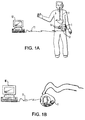
- FIG. 1A depicts an ambulatory recorder according to the present invention.
- ambulatory recorder 1 of the present invention may be carried by a patient.
- the recorder may be either carried through a mounting in the back of the recorder enclosure which fastens to a patient's belt 5, or the same mounting may be coupled to be carried using a shoulder harness (not shown).
- the recorder is coupled to the patient 4 through one or more sensing catheters 2.
- Sensing catheters may be positioned in any area of the patient's body, from which data is to be sensed, including the esophagus, as depicted in this FIG.
- the ambulatory recorder of the present invention may be used to collect many or various types of data including gastrointestinal (including pH and pressure), neurological, as well as neuromuscular, EEG or EMG data.
- various sensing catheters which may be coupled to the device are manometry catheters and pH testing catheters, including the Synectics Medical AB, Sweden Model G 91-9 series of Multi use pH catheters; Synectics Medical AB Model G 91-2 series of Multi use pH catheters with perfusion port; or the Zinectics Inc., Salt Lake City, Utah disposable 24 pH catheter Model series G91-6 or G 91-7. While a single catheter 2 is shown depicted in this figure, the recorder further permits two separate sensors to be coupled to the device, as seen in FIG. 1B.
- the recorder may also communicate with a host PC 10 via an infra red data link facility through an IRDA connection 11, for example, a JETEYE ESI-57680 available form Extended Systems, Inc., Boise, Idaho, which connects with the recorder using the Infra Red Data Association 1.1 Connection Protocol.
- an IRDA connection 11 for example, a JETEYE ESI-57680 available form Extended Systems, Inc., Boise, Idaho, which connects with the recorder using the Infra Red Data Association 1.1 Connection Protocol.
- the infra red data connection makes a link to infra red port 12 on recorder.
- FIG. 1B illustrates a further manner in which the recorder 1 may also have an infra red data communication link made with a host PC.
- the infra red data communication link may be further made when the recorder is not worn by the patient.
- the infra red data components and recorder case permit such a link to be made when the device is worn as shown in FIG. 1A as well as if the device is merely removed from the patient and positioned in proximity to mouse 11.
- FIG. 2 is a block diagram of the data recording system shown in FIG. 1B.
- recorder 1 features a battery 20 which is coupled to the signal conditioning/data acquisition block that is driven by a real time processor 21, the battery is coupled as well as to a non-real time processor 22 that runs the application.
- real time processor 21 is a lower power processor which is used to sample data which is received from sensor input 23 by a sensor attached thereto (not shown in this FIG.).
- Sampling is achieved through the signal conditioning providing an excitation to the sensor coupled to sensor input 23.
- excitation voltage is often used to power and, thus, permit sensing to occur in a variety of different types of sensors, including pressure sensors, as is well known in the art.
- the sampling and sensing controls are provided by the real time processor 21.
- Real time processor also drives an LED indicator 25 to show the system is running even when the screen is off.
- this processor is coupled to second non-real time processor 22.
- Second processor 22 is provided primarily to perform those high processing operations associated with multitasking, graphical user interface, floating point calculation, Infra Red communication and long term memory storage.
- second processor is primarily provided to operate a Windows CE operating system as well as one or more embedded applications, as depicted.
- this processor is coupled to audible buzzer 31 as well as keyboard controls 32, a screen 33 and non-volatile memory 30.
- Non-volatile memory 30 provides a long term memory for the device such that data can be recorded and preserved even if power is lost.
- the keyboard controls processes a series of four push buttons, each of which provides one or more different types of system inputs, as provided by the Windows CETM operating system, available from Microsoft Corporation, Redmond, Washington.
- the recorder features an infra red port 35 to communicate with the host PC.
- the infra red connection permits the recorder 1 to receive and exchange data with host PC 10.
- the host PC includes both a Windows 98TM operating system available from Microsoft Corporation, Redmond, Washington, as well as one or more host applications. Host applications permit the treatment of the recorded values and help for diagnostics.
- the real time processor is the model PIC16LC67 from Microchip Technology Inc., Chandler, Arizona; the non real time processor is the model ElanSC400 from Advanced Micro Devices, Inc. Sunnyvale, California; and non-volatile memory is the model Minicard AMMCL004AWP from Advanced Micro Devices, Inc. Sunnyvale, California.
- the recorder of the preferred embodiment operates by sampling data from the real time processor 21.
- the real time processor includes a buffer memory which is a volatile memory, such as RAM which temporarily stores the sampled data sets collected during each microprocessor wake-up or tick cycle. Prior to the memory being filled, however, it is important that the memory buffer contents be transferred to the non-volatile permanent memory for further future access and analysis.
- the number of channels which are sampled as well as the frequencies at which each of these channels are sampled may be programmed, there are possible variations between the sizes of the data points collected during each processor wake-up cycle.
- one of the problems which may occur is, prior to the memory buffer having its contents transferred to the non-volatile memory, the buffer itself can be filled within a processor wake-up cycle. At his point the remaining data to be sampled could be lost.
- the present invention solves this problem by monitoring the memory size of the buffer along with the amount of samples to be collected during each specific tick. In such a manner, the present invention permits the recorder to transfer and manage the memory buffer size such that there will always be room for the complete set of data samples scheduled to be collected during the next tick cycle.
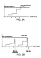
- FIG. 3A illustrates a buffer being filled in the middle of a tick.
- the memory has a maximum buffer size M.
- memory buffer has an amount of data stored into it. An equal amount of data is stored during ticks 2 and 3. (Note, in this example, an unequal amount of data is collected at each tick, because of different sampling rate by channel although as can be appreciated equal amounts of data can be collected over various cycles in the case of same sampling rate by channel).
- the memory had less capacity than the amount of data which was collected during the tick, i.e. the maximum buffer size M was exceeded prior to the full amount of data being collected during tick 4. As illustrated, this resulted in data being lost, i.e. not stored in the memory and, thus, not able to be stored in the non-volatile permanent memory for further analysis.
- FIG. 3B further illustrates how to avoid the overflow:
- the real time processor needs to download its buffer after a completed sampling every 3 ticks.
- the buffer is therefore emptied before reaching its limit.
- the principle is to calculate the maximal number of ticks to complete before emptying the buffer, that will assure that the buffer is never overflowed according to how many channels the device samples and according to the different frequencies.
- the number of ticks max is calculated before it starts to sample and it is used during the entire recording time.
- the advantage of calculating only once and not on the fly after each tick is that the microprocessor uses less computation cycle therefore less energy which is a mandatory criteria in portable devices.
- FIG. 3C further illustrates the memory filling and availability during each processor wake-up cycle or tick.
- the sampling channels and frequencies used in this illustration do not correspond with those used in FIGS. 3A and 3B, discussed above.
- the processor samples along channels 1 and 2.
- no samples are stored in the memory and twelve spaces are available.
- two samples are stored in volatile memory and ten remaining spaces are available.
- tick 2 sampling occurs along channels 1 and 4.
- two additional samples are collected and the number of samples in the volatile memory increases from two, at the beginning of the wake-up cycle, to four, at the end of the wake-up cycle.
- the number of spaces available in the volatile memory decreases from ten, at the beginning of the wake-up cycle, to eight, at the end of the wake-up cycle.
- a continual increase in the number of samples in the volatile memory occurs through ticks 3, 4 and 5 with a concomitant decrease in the number of spaces available in the volatile memory, until, as seen, at the end of tick 5, the number of spaces available in volatile memory at the end of the wake-up cycle is one.
- this causes data loss during tick 6, i.e. during tick 6 channels 1, 2 and 3 are to be sampled.
- the number of samples in the volatile memory at the beginning of the wake-up cycle is eleven and only one space is available in the volatile memory at the beginning of the wake-up cycle.
- tick 6 there is not enough space in the volatile memory to store all the samples which are desired. At this point, a memory overfill would be seen and some or all of the data to be collected in tick 6 would be lost.
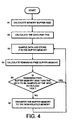
- FIG. 4 depicts the general steps used to manage the memory buffer size such that there will always be room for the complete set of data samples scheduled to be collected during the next tick cycle.
- the memory buffer size is calculated.
- the recorder proceeds to block 52 and calculates the data per tick
- the recorder proceeds to block 53 and samples data and stores it in the buffer memory.
- the remaining free buffer memory is calculated.
- a decision is made whether the remaining free buffer memory is less than the data before next scheduled tick. If it is, the recorder proceeds back to block 53 and samples the data and puts it in the memory.
- the recorder would proceed to block 56 and transfer the buffer memory to the non-volatile memory prior to again returning to block 53. In such a manner, the recorder is able to manage the buffer memory size so that there is always enough remaining free buffer memory to permit the next data set to be stored.
- FIG. 5 illustrates how to calculate the number of tick max per buffer.
- the initial condition is that every channel has been assigned a sampling frequency. We can take for example 3 channels with channel 1 at 1/4Hz, channel 2 at 1Hz and channel 3 at 4Hz.
- the device examines the frequencies at which sampling is to occur for every channel and calculates the lowest common frequency (4Hz in our example).
- the device sets or determinates a respective tick count for each individual frequency.
- the Tick count represents the number of ticks to wait before sampling a channel.
- a value of 1 means that the channel has to be sampled every tick, a value of 2 means every 2 ticks and so on.
- FIG. 6 is a back view of the recorder. As seen, recorder 1 features a belt loop 174 which may be used to mount the recorder to a patient using either the patient's belt or the shoulder strap.
- FIG. 7 is a side view of recorder 1. As further seen in this view, housing 155 features a pair of sensor inputs 175 and 176. In the preferred embodiment, input 175 is for a pH catheter while input 176 is for a pressure measuring catheter.
Abstract
Description
- The present invention relates to ambulatory recording, for medical and especially for diagnostic purposes, and particularly to an ambulatory recorder having a volatile and a non-volatile memory.
- Various physiologic signals are often recorded and analyzed. These signals may include digestive pH, various digestive motility and pressure signals, EEG and EMG, to list only a few.
- Typically, physicians require the concurrent recording of a variety of physiologic signals. For example, gastric pH is often collected at the same time as pressure. Through the concurrent collection of various parameters the physician may better understand the patient's condition.
- Ambulatory recording and recorders are widely used to collect such data. Such devices include the Digitrapper Mk III™ ambulatory recorder from Synectics Medical AB, the GastroScan II™ from Medical Instruments Corporation, and the SuperLogger™ from Sandhill Scientific. These types of devices make it possible for patients to remain at home, or at the least be ambulant in a hospital setting while physiological data is recorded. Typically the devices comprise a lightweight recorder in which the desired physiological data signals are temporarily stored and later downloaded for future analysis.
- Many types of physiological data may be recorded, including ECG (Electrocardiogram), EEG (Electroencephalogram) or pH and pressure (Motility) in the gastrointestinal tract. Preferably such a recorder should be able to record among a programmable number of channels at a variety of programmable frequencies.
- Among the problems with current recorders, however, is that of energy usage. Such recorders, because they must be ambulatory, are battery powered. Thus an ambulatory medical recorder must minimize energy usage while performing almost constant sampling across a variable number of channels at one or more frequencies.
- One approach to limit power consumption, while still permitting an enhanced graphical user interface, is to equip the device with two microprocessors. A first, real time processor for sampling, which operates with a relatively low current drain, and a second, non real time processor for permitting an enhanced graphical user interface.
- Such a device, however, having a real time (sampling) processor, having volatile memory, and a non real time (operating system) processor, having a non volatile memory, must periodically transfer the data collected in the volatile memory to the non volatile memory.
- Typically such a device would sample and collect data during specific processor power on or "awake" cycles. One problem which may arise during such data transfer is if the device is sampling along several channels, and if the volatile memory is filled before all the channels to be sampled at a particular time are actually sampled. That is, if the buffer would be filled during a tick before all the channels are sampled, then the remaining data which should be collected would not be and thus would be lost.
- Accordingly, in a first aspect, the invention provides an ambulatory recorder comprising:
- a sensor for sensing at least one physiologic parameter from a patient;
- a first processor to perform a first process on the at least sensed physiologic parameter and create a first data set, the first processor further having a first volatile memory in which the first data set is stored, the first volatile memory having a limit.
- a second processor to perform a second process on the sensed physiologic parameter, the first processor coupled to the second processor so that the data may be transferred by the first processor to the second processor; and
- means for managing the amount of data stored in the first volatile memory so that the first volatile memory limit is not reached.
-
- According to a second aspect, the invention provides an ambulatory recorder comprising:
- a sensor for sensing at least one physiologic parameter from a patient;
- a first processor to perform a first process to the at least sensed physiologic parameter and create a first data set, the processor performing the process at each processor tick, the first processor further having a first volatile memory in which the first data set is stored, the first volatile memory buffer having a size limit; and
- means for calculating the amount of data acquired per tick.
-
- The recorder actively manages the transfer of the data in the volatile to the non volatile memory. Preferably, the sampling frequency and number of channels to be sampled are monitored. These parameters, along with the total buffer size available may be used to determine the final complete data set which can be stored in the buffer. Thereafter, the contents of the buffer are transferred to the non volatile memory. In such a manner the recorder avoids filling the buffer in the middle of a sampling tick, in which case the remaining data to be sampled would be lost.
- Preferred embodiments of the invention will now be described, by way of example only, with reference to the accompanying drawigs.
- FIG. 1A depicts an ambulatory recorder according to the present invention.
- FIG. 1B illustrates a further manner in which the
recorder 1 may also have an infra red data communication link made with a host PC. - FIG. 2 is a block diagram of the data recording system shown in FIG. 1B.
- FIG. 3A illustrates a buffer being filled in the middle of a tick.
- FIG. 3B further illustrates how to avoid the overflow:
- FIG. 3C further illustrates the memory filling and availability during each processor wake-up cycle or tick.
- FIG. 4 depicts the general steps used to manage the memory buffer size such that there will always be room for the complete set of data samples scheduled to be collected during the next tick cycle.
- FIG. 5 illustrates how to calculate the number of tick max per buffer.
- FIG. 6 is a back view of the recorder.
- FIG. 7 is a side view of the recorder
-
- The FIGS. are not necessarily to scale.
- FIG. 1A depicts an ambulatory recorder according to the present invention. As seen,
ambulatory recorder 1 of the present invention may be carried by a patient. In the preferred embodiment, the recorder may be either carried through a mounting in the back of the recorder enclosure which fastens to a patient'sbelt 5, or the same mounting may be coupled to be carried using a shoulder harness (not shown). As seen, the recorder is coupled to thepatient 4 through one or moresensing catheters 2. Sensing catheters may be positioned in any area of the patient's body, from which data is to be sensed, including the esophagus, as depicted in this FIG. It should be noted, the ambulatory recorder of the present invention may be used to collect many or various types of data including gastrointestinal (including pH and pressure), neurological, as well as neuromuscular, EEG or EMG data. - Among the various sensing catheters which may be coupled to the device are manometry catheters and pH testing catheters, including the Synectics Medical AB, Stockholm, Sweden Model G 91-9 series of Multi use pH catheters; Synectics Medical AB Model G 91-2 series of Multi use pH catheters with perfusion port; or the Zinectics Inc., Salt Lake City, Utah disposable 24 pH catheter Model series G91-6 or G 91-7. While a
single catheter 2 is shown depicted in this figure, the recorder further permits two separate sensors to be coupled to the device, as seen in FIG. 1B. - As further seen in this figure, the recorder may also communicate with a host PC 10 via an infra red data link facility through an IRDA
connection 11, for example, a JETEYE ESI-57680 available form Extended Systems, Inc., Boise, Idaho, which connects with the recorder using the Infra Red Data Association 1.1 Connection Protocol. As seen, the infra red data connection makes a link to infrared port 12 on recorder. - FIG. 1B illustrates a further manner in which the
recorder 1 may also have an infra red data communication link made with a host PC. In particular, the infra red data communication link may be further made when the recorder is not worn by the patient. As discussed in more detail below, one of the advantages of the preferred embodiment is that the infra red data components and recorder case permit such a link to be made when the device is worn as shown in FIG. 1A as well as if the device is merely removed from the patient and positioned in proximity tomouse 11. - FIG. 2 is a block diagram of the data recording system shown in FIG. 1B. As seen,
recorder 1 features abattery 20 which is coupled to the signal conditioning/data acquisition block that is driven by areal time processor 21, the battery is coupled as well as to anon-real time processor 22 that runs the application. As disclosed in more detail below,real time processor 21 is a lower power processor which is used to sample data which is received fromsensor input 23 by a sensor attached thereto (not shown in this FIG.). - Sampling is achieved through the signal conditioning providing an excitation to the sensor coupled to
sensor input 23. Such excitation voltage is often used to power and, thus, permit sensing to occur in a variety of different types of sensors, including pressure sensors, as is well known in the art. The sampling and sensing controls are provided by thereal time processor 21. Real time processor also drives anLED indicator 25 to show the system is running even when the screen is off. - As further seen, this processor is coupled to second
non-real time processor 22.Second processor 22 is provided primarily to perform those high processing operations associated with multitasking, graphical user interface, floating point calculation, Infra Red communication and long term memory storage. In particular, second processor is primarily provided to operate a Windows CE operating system as well as one or more embedded applications, as depicted. As further seen, this processor is coupled toaudible buzzer 31 as well as keyboard controls 32, ascreen 33 andnon-volatile memory 30.Non-volatile memory 30 provides a long term memory for the device such that data can be recorded and preserved even if power is lost. In the preferred embodiment, the keyboard controls processes a series of four push buttons, each of which provides one or more different types of system inputs, as provided by the Windows CE™ operating system, available from Microsoft Corporation, Redmond, Washington. - As further seen in this figure, the recorder features an infra
red port 35 to communicate with the host PC. As depicted in FIG. 1B, the infra red connection permits therecorder 1 to receive and exchange data withhost PC 10. The host PC, as seen, includes both aWindows 98™ operating system available from Microsoft Corporation, Redmond, Washington, as well as one or more host applications. Host applications permit the treatment of the recorded values and help for diagnostics. - In the preferred embodiment the real time processor is the model PIC16LC67 from Microchip Technology Inc., Chandler, Arizona; the non real time processor is the model ElanSC400 from Advanced Micro Devices, Inc. Sunnyvale, California; and non-volatile memory is the model Minicard AMMCL004AWP from Advanced Micro Devices, Inc. Sunnyvale, California.
- As discussed above, the recorder of the preferred embodiment operates by sampling data from the
real time processor 21. The real time processor includes a buffer memory which is a volatile memory, such as RAM which temporarily stores the sampled data sets collected during each microprocessor wake-up or tick cycle. Prior to the memory being filled, however, it is important that the memory buffer contents be transferred to the non-volatile permanent memory for further future access and analysis. - Because the number of channels which are sampled as well as the frequencies at which each of these channels are sampled may be programmed, there are possible variations between the sizes of the data points collected during each processor wake-up cycle. As mentioned above, one of the problems which may occur is, prior to the memory buffer having its contents transferred to the non-volatile memory, the buffer itself can be filled within a processor wake-up cycle. At his point the remaining data to be sampled could be lost.
- The present invention solves this problem by monitoring the memory size of the buffer along with the amount of samples to be collected during each specific tick. In such a manner, the present invention permits the recorder to transfer and manage the memory buffer size such that there will always be room for the complete set of data samples scheduled to be collected during the next tick cycle.
- FIG. 3A illustrates a buffer being filled in the middle of a tick. As seen, the memory has a maximum buffer size M. At
tick 1 memory buffer has an amount of data stored into it. An equal amount of data is stored duringticks tick 4, the memory had less capacity than the amount of data which was collected during the tick, i.e. the maximum buffer size M was exceeded prior to the full amount of data being collected duringtick 4. As illustrated, this resulted in data being lost, i.e. not stored in the memory and, thus, not able to be stored in the non-volatile permanent memory for further analysis. - FIG. 3B further illustrates how to avoid the overflow: The real time processor needs to download its buffer after a completed sampling every 3 ticks. The buffer is therefore emptied before reaching its limit. The principle is to calculate the maximal number of ticks to complete before emptying the buffer, that will assure that the buffer is never overflowed according to how many channels the device samples and according to the different frequencies. The number of ticks max is calculated before it starts to sample and it is used during the entire recording time. The advantage of calculating only once and not on the fly after each tick is that the microprocessor uses less computation cycle therefore less energy which is a mandatory criteria in portable devices.
- FIG. 3C further illustrates the memory filling and availability during each processor wake-up cycle or tick. The reader should note the sampling channels and frequencies used in this illustration do not correspond with those used in FIGS. 3A and 3B, discussed above. As seen, at
tick 1, the processor samples alongchannels tick 2 sampling occurs alongchannels ticks tick 5, the number of spaces available in volatile memory at the end of the wake-up cycle is one. As seen, this causes data loss duringtick 6, i.e. duringtick 6channels tick 6 there is not enough space in the volatile memory to store all the samples which are desired. At this point, a memory overfill would be seen and some or all of the data to be collected intick 6 would be lost. - FIG. 4 depicts the general steps used to manage the memory buffer size such that there will always be room for the complete set of data samples scheduled to be collected during the next tick cycle. As seen in step 51, the memory buffer size is calculated. Next, the recorder proceeds to block 52 and calculates the data per tick Next, the recorder proceeds to block 53 and samples data and stores it in the buffer memory. In block 54 the remaining free buffer memory is calculated. Next, at 55 a decision is made whether the remaining free buffer memory is less than the data before next scheduled tick. If it is, the recorder proceeds back to block 53 and samples the data and puts it in the memory. If, however, the remaining free buffer memory is less than the size of the data set before the next scheduled tick, the recorder would proceed to block 56 and transfer the buffer memory to the non-volatile memory prior to again returning to block 53. In such a manner, the recorder is able to manage the buffer memory size so that there is always enough remaining free buffer memory to permit the next data set to be stored.
- FIG. 5 illustrates how to calculate the number of tick max per buffer. The initial condition is that every channel has been assigned a sampling frequency. We can take for example 3 channels with
channel 1 at 1/4Hz,channel 2 at 1Hz andchannel 3 at 4Hz. At 41, the device examines the frequencies at which sampling is to occur for every channel and calculates the lowest common frequency (4Hz in our example). - Next, at 42 the device sets or determinates a respective tick count for each individual frequency. The Tick count represents the number of ticks to wait before sampling a channel. A value of 1 means that the channel has to be sampled every tick, a value of 2 means every 2 ticks and so on. We get in our example a NbTick for
channel 1 of 16, forchannel 2 of 4 and forchannel 3 of 1. -
Step 43 calculates the Number of Ticks to fill the buffer (NbTicksMax) by: - FIG. 6 is a back view of the recorder. As seen,
recorder 1 features abelt loop 174 which may be used to mount the recorder to a patient using either the patient's belt or the shoulder strap. - FIG. 7 is a side view of
recorder 1. As further seen in this view,housing 155 features a pair ofsensor inputs input 175 is for a pH catheter whileinput 176 is for a pressure measuring catheter.
Claims (13)
- An ambulatory recorder (1) comprising:a sensor (2) for sensing at least one physiologic parameter from a patient;a first processor (21) to perform a first process on the at least sensed physiologic parameter and create a first data set, the first processor further having a first volatile memory in which the first data set is stored, the first volatile memory having a limit.a second processor (22) to perform a second process on the sensed physiologic parameter, the first processor coupled to the second processor so that the data may be transferred by the first processor to the second processor; andmeans for managing the amount of data stored in the first volatile memory so that the first volatile memory limit is not reached.
- An ambulatory recorder according to claim 1 wherein the means for managing further comprises means for transferring data from the first volatile buffer memory to the second processor.
- An ambulatory recorder according to claim 1 further comprising a non volatile memory, the non volatile memory coupled to the second processor.
- An ambulatory recorder (1) comprising:a sensor (2) for sensing at least one physiologic parameter from a patient;a first processor (21) to perform a first process to the at least sensed physiologic parameter and create a first data set, the processor performing the process at each processor tick, the first processor further having a first volatile memory in which the first data set is stored, the first volatile memory buffer having a size limit; andmeans for calculating the amount of data acquired per tick.
- An ambulatory recorder according to any preceding claim further comprising means for calculating the volatile memory buffer size limit
- An ambulatory recorder according to any preceding claim further comprising means for sampling medical data and storing said sampled data in the volatile buffer memory.
- An ambulatory recorder according to claim 6 further comprising means for calculating remaining free volatile buffer memory.
- An ambulatory recorder according to claim 7 further comprising means for determining whether the remaining free volatile buffer memory is less than the data to be sampled at next scheduled tick.
- An ambulatory recorder according to claim 8 when dependent on claim 3 further comprising means for transfering the volatile buffer memory to the non-volatile memory.
- An ambulatory recorder according to any preceding claim further comprising a mounting (74) for mounting the ambulatory recorder to a patient.
- An ambulatory recorder according to claim 10 wherein the mounting comprises a loop (74) configured for a belt or a shoulder strap to be inserted therethrough.
- An ambulatory recorder according to any preceding claim wherein the sensor comprises a pH sensing catheter (2).
- An ambulatory recorder according to claim 4 or any claim dependent thereon further comprising means for calculating the amount of data acquired per tick.
Applications Claiming Priority (2)
| Application Number | Priority Date | Filing Date | Title |
|---|---|---|---|
| US09/130,150 US6128520A (en) | 1998-08-06 | 1998-08-06 | Ambulatory recorder having volatile and non-volatile memories |
| US130150 | 1998-08-06 |
Publications (2)
| Publication Number | Publication Date |
|---|---|
| EP0978253A2 true EP0978253A2 (en) | 2000-02-09 |
| EP0978253A3 EP0978253A3 (en) | 2001-04-04 |
Family
ID=22443299
Family Applications (1)
| Application Number | Title | Priority Date | Filing Date |
|---|---|---|---|
| EP99115040A Withdrawn EP0978253A3 (en) | 1998-08-06 | 1999-08-03 | Ambulatory recorder having volatile and non-volatile memory |
Country Status (2)
| Country | Link |
|---|---|
| US (1) | US6128520A (en) |
| EP (1) | EP0978253A3 (en) |
Cited By (2)
| Publication number | Priority date | Publication date | Assignee | Title |
|---|---|---|---|---|
| FR2831294A1 (en) * | 2001-10-23 | 2003-04-25 | Ikare | System for acquisition of biological signal such as ECG using a portable recorder to send data to a remote server, uses remote server to control dialogue with recorder to collect measurements |
| WO2017139340A1 (en) * | 2016-02-12 | 2017-08-17 | Cardiac Pacemakers, Inc. | Triggering storage of onset of physiologic condition |
Families Citing this family (10)
| Publication number | Priority date | Publication date | Assignee | Title |
|---|---|---|---|---|
| US6606510B2 (en) | 2000-08-31 | 2003-08-12 | Mallinckrodt Inc. | Oximeter sensor with digital memory encoding patient data |
| US7433831B2 (en) | 2002-06-04 | 2008-10-07 | Philip Morris Usa Inc. | Automatic price display control by emulation of electronic cash register price lookup |
| US7545272B2 (en) | 2005-02-08 | 2009-06-09 | Therasense, Inc. | RF tag on test strips, test strip vials and boxes |
| US8951190B2 (en) * | 2005-09-28 | 2015-02-10 | Zin Technologies, Inc. | Transfer function control for biometric monitoring system |
| US8200320B2 (en) * | 2006-03-03 | 2012-06-12 | PhysioWave, Inc. | Integrated physiologic monitoring systems and methods |
| US7668588B2 (en) | 2006-03-03 | 2010-02-23 | PhysioWave, Inc. | Dual-mode physiologic monitoring systems and methods |
| US20070208232A1 (en) * | 2006-03-03 | 2007-09-06 | Physiowave Inc. | Physiologic monitoring initialization systems and methods |
| JP5710767B2 (en) | 2010-09-28 | 2015-04-30 | マシモ コーポレイション | Depth of consciousness monitor including oximeter |
| US9474475B1 (en) * | 2013-03-15 | 2016-10-25 | Abbott Diabetes Care Inc. | Multi-rate analyte sensor data collection with sample rate configurable signal processing |
| WO2016057553A1 (en) | 2014-10-07 | 2016-04-14 | Masimo Corporation | Modular physiological sensors |
Citations (4)
| Publication number | Priority date | Publication date | Assignee | Title |
|---|---|---|---|---|
| US5086778A (en) * | 1989-07-21 | 1992-02-11 | Mueller & Sebastiani Elektronik Gmbh | Method and system for evaluating data picked-up by means of long term ecg devices |
| EP0512667A1 (en) * | 1991-05-03 | 1992-11-11 | DIAGNOSTIC MEDICAL INSTRUMENTS Inc. | Ambulatory electrocardiography monitor using disk storage |
| EP0519137A1 (en) * | 1991-06-20 | 1992-12-23 | Caliber Medical Corporation | Optical/electrical transceiver |
| WO1997017012A1 (en) * | 1995-11-09 | 1997-05-15 | Del Mar Avionics | Modular physiological computer-recorder |
Family Cites Families (77)
| Publication number | Priority date | Publication date | Assignee | Title |
|---|---|---|---|---|
| US5338157B1 (en) * | 1992-09-09 | 1999-11-02 | Sims Deltec Inc | Systems and methods for communicating with ambulat |
| US4370983A (en) * | 1971-01-20 | 1983-02-01 | Lichtenstein Eric Stefan | Computer-control medical care system |
| NL7102659A (en) * | 1971-02-27 | 1972-08-29 | ||
| US3898984A (en) * | 1974-02-04 | 1975-08-12 | Us Navy | Ambulatory patient monitoring system |
| US4003379A (en) * | 1974-04-23 | 1977-01-18 | Ellinwood Jr Everett H | Apparatus and method for implanted self-powered medication dispensing |
| AT356244B (en) * | 1975-01-31 | 1980-04-10 | Medicor Muevek | PORTABLE MEDICAL DIAGNOSTIC APPARATUS |
| US4129125A (en) * | 1976-12-27 | 1978-12-12 | Camin Research Corp. | Patient monitoring system |
| US4353375A (en) * | 1977-04-26 | 1982-10-12 | The United States Of America As Represented By The Department Of Health & Human Services | Activity monitor for ambulatory subjects |
| US4183354A (en) * | 1977-07-18 | 1980-01-15 | Cardiodyne, Inc. | Ambulatory electrocardiographic recorder |
| US4198963A (en) * | 1978-10-19 | 1980-04-22 | Michigan Instruments, Inc. | Cardiopulmonary resuscitator, defibrillator and monitor |
| US4333475A (en) * | 1979-12-06 | 1982-06-08 | Medical Concepts, Inc. | Ambulatory cardiac monitoring system |
| US4365636A (en) * | 1981-06-19 | 1982-12-28 | Medicon, Inc. | Method of monitoring patient respiration and predicting apnea therefrom |
| US4529401A (en) * | 1982-01-11 | 1985-07-16 | Cardiac Pacemakers, Inc. | Ambulatory infusion pump having programmable parameters |
| US5526809A (en) * | 1982-03-22 | 1996-06-18 | Mountpelier Investments, S.A. | Hollow viscous and soild organ tonometry |
| US4531527A (en) * | 1982-04-23 | 1985-07-30 | Survival Technology, Inc. | Ambulatory monitoring system with real time analysis and telephone transmission |
| US4771772A (en) * | 1982-08-09 | 1988-09-20 | Medtronic, Inc. | Robotic implantable medical device and/or component restoration system |
| US4628928A (en) * | 1982-08-09 | 1986-12-16 | Medtronic, Inc. | Robotic implantable medical device and/or component restoration system |
| US4748562A (en) * | 1983-05-04 | 1988-05-31 | Akron City Hospital | Portable circuit and method for performing a time study and analysis of bodily characteristics |
| US4503859A (en) * | 1983-06-16 | 1985-03-12 | William Beaumont Hospital | Esophageal function and EKG monitor |
| US4592018A (en) * | 1983-08-29 | 1986-05-27 | Vita-Stat Medical Services, Inc. | Removable RAM package for ambulatory medical monitor |
| US4684367A (en) * | 1985-04-12 | 1987-08-04 | Meditec Research Associates | Ambulatory intravenous delivery system |
| DE3516018A1 (en) * | 1985-05-02 | 1986-12-18 | Holger 1000 Berlin Kruse | PORTABLE DEVICE FOR DETERMINING THE STOMACH FUNCTION ON THE BASIS OF THE ACIDIC ACID |
| JPS62324A (en) * | 1985-06-27 | 1987-01-06 | 本山 博 | Apparatus for diagnosis of internal organs and nerval function |
| US4667682A (en) * | 1985-07-02 | 1987-05-26 | Creative Medical Systems, Inc. | Cardiac ambulatory monitor |
| US5012411A (en) * | 1985-07-23 | 1991-04-30 | Charles J. Policastro | Apparatus for monitoring, storing and transmitting detected physiological information |
| US5111818A (en) * | 1985-10-08 | 1992-05-12 | Capintec, Inc. | Ambulatory physiological evaluation system including cardiac monitoring |
| US5007427A (en) * | 1987-05-07 | 1991-04-16 | Capintec, Inc. | Ambulatory physiological evaluation system including cardiac monitoring |
| US4632119A (en) * | 1985-10-23 | 1986-12-30 | University Of Health Sciences/The Chicago Medical School | Ambulatory esophageal pH monitor |
| US4715385A (en) * | 1986-09-26 | 1987-12-29 | Marquette Electronics, Inc. | Patient monitoring system having transportable data module and display unit |
| US4895161A (en) * | 1986-09-26 | 1990-01-23 | Marquette Electronics | Transportable data module and display unit for patient monitoring system |
| US5072458A (en) * | 1987-05-07 | 1991-12-17 | Capintec, Inc. | Vest for use in an ambulatory physiological evaluation system including cardiac monitoring |
| US5025374A (en) * | 1987-12-09 | 1991-06-18 | Arch Development Corp. | Portable system for choosing pre-operative patient test |
| US5010888A (en) * | 1988-03-25 | 1991-04-30 | Arzco Medical Electronics, Inc. | Method and apparatus for detection of posterior ischemia |
| DE68914720T2 (en) * | 1988-05-31 | 1994-11-03 | Sharp Kk | Outpatient electrocardiography device. |
| US4900305A (en) * | 1988-06-27 | 1990-02-13 | Queen's University At Kingston | Ambulatory infusion pump |
| US5131816A (en) * | 1988-07-08 | 1992-07-21 | I-Flow Corporation | Cartridge fed programmable ambulatory infusion pumps powered by DC electric motors |
| US4917092A (en) * | 1988-07-13 | 1990-04-17 | Medical Designs, Inc. | Transcutaneous nerve stimulator for treatment of sympathetic nerve dysfunction |
| US4974599A (en) * | 1988-10-25 | 1990-12-04 | Sharp Kabushiki Kaisha | Portable electrocardiograph |
| GB8825800D0 (en) * | 1988-11-04 | 1988-12-07 | Baker J | Cardiac device |
| US5042481A (en) * | 1989-01-31 | 1991-08-27 | Sharp Kabushiki Kaisha | Body electrode holder |
| US5107835A (en) * | 1989-05-22 | 1992-04-28 | Physiodynamics | Electrotherapeutic treatment |
| US5016636A (en) * | 1989-06-08 | 1991-05-21 | Phyllis Kulakowski | Belt for retaining sensing electrodes on the chest of an infant afflicted with Apnea |
| US5158083A (en) * | 1989-10-23 | 1992-10-27 | Mountpelier Investments, S.A. | Miniature pco2 probe for in vivo biomedical applications |
| US5111396A (en) * | 1989-11-09 | 1992-05-05 | Instromedix, Inc. | Portable ecg data-storage apparatus |
| US5213568A (en) * | 1990-03-30 | 1993-05-25 | Medtronic Inc. | Activity controlled electrotransport drug delivery device |
| GB9010774D0 (en) * | 1990-05-14 | 1990-07-04 | Oxford Medical Ltd | Ambulatory monitor |
| US5113869A (en) * | 1990-08-21 | 1992-05-19 | Telectronics Pacing Systems, Inc. | Implantable ambulatory electrocardiogram monitor |
| US5117827A (en) * | 1990-10-26 | 1992-06-02 | Sandhill Scientific, Inc. | Apparatus and method for ambulatory reflux monitoring |
| US5388587A (en) * | 1990-12-04 | 1995-02-14 | Dorsograf Ab | Method and apparatus for measuring the transport time of nerve signals excited in different dermatoms of a patient |
| US5188104A (en) * | 1991-02-01 | 1993-02-23 | Cyberonics, Inc. | Treatment of eating disorders by nerve stimulation |
| US5222503A (en) * | 1991-04-24 | 1993-06-29 | Beth Israel Hospital Association | Ambulatory electroencephalography system |
| US5224485A (en) * | 1991-05-28 | 1993-07-06 | Hewlett-Packard Company | Portable data acquisition unit |
| US5273033A (en) * | 1991-09-19 | 1993-12-28 | Murray Electronics Associates Limited Partnership | Electrical stimulation for treatment of osteoarthritis |
| US5343870A (en) * | 1991-11-12 | 1994-09-06 | Quinton Instrument Company | Recorder unit for ambulatory ECG monitoring system |
| US5238001A (en) * | 1991-11-12 | 1993-08-24 | Stuart Medical Inc. | Ambulatory patient monitoring system having multiple monitoring units and optical communications therebetween |
| US5305202A (en) * | 1991-11-12 | 1994-04-19 | Quinton Instrument Company | Ambulatory ECG analysis system |
| US5431634A (en) * | 1992-03-06 | 1995-07-11 | Baxter International Inc. | Ambulatory pump |
| FR2690622B1 (en) * | 1992-04-29 | 1995-01-20 | Chronotec | Programmable ambulatory infusion pump system. |
| US5263491A (en) * | 1992-05-12 | 1993-11-23 | William Thornton | Ambulatory metabolic monitor |
| US5292344A (en) * | 1992-07-10 | 1994-03-08 | Douglas Donald D | Percutaneously placed electrical gastrointestinal pacemaker stimulatory system, sensing system, and pH monitoring system, with optional delivery port |
| US5307263A (en) * | 1992-11-17 | 1994-04-26 | Raya Systems, Inc. | Modular microprocessor-based health monitoring system |
| US5438985A (en) * | 1993-01-25 | 1995-08-08 | Synectics Medical, Incorporated | Ambulatory recording of the presence and activity of substances in gastro-intestinal compartments |
| US5355892A (en) * | 1993-02-10 | 1994-10-18 | Hewlett-Packard Corporation | Method and apparatus for controlling a medical device with a macro instruction |
| US5657759A (en) * | 1993-05-13 | 1997-08-19 | Synectics Medical, Incorporated | Measurement of gastric emptying and gastrointestinal output |
| US5411022A (en) * | 1993-07-01 | 1995-05-02 | Mccue; Michael | Continuous pH monitoring system and method of using same |
| EP0634644A1 (en) * | 1993-07-13 | 1995-01-18 | Mic Medical Instrument Corporation | Device for determining the 13CO2/12CO2 concentration ratio in a gas sample |
| US5368562A (en) * | 1993-07-30 | 1994-11-29 | Pharmacia Deltec, Inc. | Systems and methods for operating ambulatory medical devices such as drug delivery devices |
| CA2147166A1 (en) * | 1993-09-14 | 1995-03-23 | David Paul Fisher | Medical container port |
| US5381351A (en) * | 1993-10-15 | 1995-01-10 | Hewlett-Packard Corporation | Ambulatory monitor ECG pulse calibration method |
| US5479935A (en) * | 1993-10-21 | 1996-01-02 | Synectics Medical, Inc. | Ambulatory reflux monitoring system |
| US5432698A (en) * | 1994-05-31 | 1995-07-11 | Modular Instruments, Inc. | Data input and output controller for anesthesia monitoring system |
| JP3235632B2 (en) * | 1994-06-17 | 2001-12-04 | グラム株式会社 | Apparatus for measuring electrogastrogram and electrogram and method for producing the same |
| US5545183A (en) * | 1994-12-07 | 1996-08-13 | Ventritex, Inc. | Method and apparatus for delivering defibrillation therapy through a sensing electrode |
| US5645068A (en) * | 1995-03-20 | 1997-07-08 | Bioscan, Inc. | Methods and apparatus for ambulatory and non-ambulatory monitoring of physiological data using digital flash storage |
| US5704890A (en) * | 1995-05-31 | 1998-01-06 | Battelle Memorial Institute | Real time sensor for therapeutic radiation delivery |
| US5607460A (en) * | 1996-03-15 | 1997-03-04 | Angeion Corporation | Physician interface expert system for programming implantable arrythmia treatment devices |
| US5749907A (en) * | 1997-02-18 | 1998-05-12 | Pacesetter, Inc. | System and method for identifying and displaying medical data which violate programmable alarm conditions |
-
1998
- 1998-08-06 US US09/130,150 patent/US6128520A/en not_active Expired - Lifetime
-
1999
- 1999-08-03 EP EP99115040A patent/EP0978253A3/en not_active Withdrawn
Patent Citations (4)
| Publication number | Priority date | Publication date | Assignee | Title |
|---|---|---|---|---|
| US5086778A (en) * | 1989-07-21 | 1992-02-11 | Mueller & Sebastiani Elektronik Gmbh | Method and system for evaluating data picked-up by means of long term ecg devices |
| EP0512667A1 (en) * | 1991-05-03 | 1992-11-11 | DIAGNOSTIC MEDICAL INSTRUMENTS Inc. | Ambulatory electrocardiography monitor using disk storage |
| EP0519137A1 (en) * | 1991-06-20 | 1992-12-23 | Caliber Medical Corporation | Optical/electrical transceiver |
| WO1997017012A1 (en) * | 1995-11-09 | 1997-05-15 | Del Mar Avionics | Modular physiological computer-recorder |
Cited By (4)
| Publication number | Priority date | Publication date | Assignee | Title |
|---|---|---|---|---|
| FR2831294A1 (en) * | 2001-10-23 | 2003-04-25 | Ikare | System for acquisition of biological signal such as ECG using a portable recorder to send data to a remote server, uses remote server to control dialogue with recorder to collect measurements |
| WO2003034913A1 (en) * | 2001-10-23 | 2003-05-01 | Ikare | System and method of acquiring and transmitting a biological signal |
| WO2017139340A1 (en) * | 2016-02-12 | 2017-08-17 | Cardiac Pacemakers, Inc. | Triggering storage of onset of physiologic condition |
| US10702167B2 (en) | 2016-02-12 | 2020-07-07 | Cardiac Pacemakers, Inc. | Method to trigger storage of onset of physiologic condition in an implantable device |
Also Published As
| Publication number | Publication date |
|---|---|
| US6128520A (en) | 2000-10-03 |
| EP0978253A3 (en) | 2001-04-04 |
Similar Documents
| Publication | Publication Date | Title |
|---|---|---|
| US6154668A (en) | Ambulatory recorder having a real time and non-real time processors | |
| US6115622A (en) | Ambulatory recorder having enhanced sampling technique | |
| US6245013B1 (en) | Ambulatory recorder having synchronized communication between two processors | |
| US20100049006A1 (en) | Medical signal processing system with distributed wireless sensors | |
| US6847913B2 (en) | Ambulatory surface skin temperature monitor | |
| EP0978253A2 (en) | Ambulatory recorder having volatile and non-volatile memory | |
| EP2440112B1 (en) | Device for processing and transmitting measured signals for monitoring and/or controlling medical implants | |
| EP0553372B1 (en) | Method and system for monitoring vital signs | |
| CN105686807B (en) | Medical Devices | |
| EP3205265B1 (en) | Body-associated receiver and method | |
| JP4742182B2 (en) | Data transmission / reception device, data management device, data processing device, and program | |
| EP1699525B1 (en) | Multi-level averaging scheme for acquiring hemodynamic data | |
| EP2138944B1 (en) | Method, system, and computer program product for calculating daily weighted averages of glucose measurements (or derived quantities) with time-based weights | |
| US20040148199A1 (en) | System for acquiring, storing, and transmitting patient medical data | |
| US6014578A (en) | Ambulatory recorder having method of configuring size of data subject to loss in volatile memory | |
| AU2020317807B2 (en) | Method for transmitting and receiving biometric information without loss in continuous blood glucose monitoring system | |
| US20120108911A1 (en) | Medical apparatus | |
| EP1010391B1 (en) | Ambulatory recorder having a communication watchdog between two processors | |
| JPH1156801A (en) | Portable programmable biological information long-term measurement and storage system | |
| US20220395225A1 (en) | Modular wristband and sensor system | |
| EP1589464A2 (en) | Transtelephonic multifunctional electrocardiograph | |
| EP4059413A1 (en) | System for monitoring gastro-intestinal disorders | |
| Lopez et al. | Integrating wearable sensing and information technologies for human healthcare support | |
| JP3131729U (en) | Wireless portable health management Holter electrocardiograph | |
| JPH1033487A (en) | Remote data diagnosis apparatus |
Legal Events
| Date | Code | Title | Description |
|---|---|---|---|
| PUAI | Public reference made under article 153(3) epc to a published international application that has entered the european phase |
Free format text: ORIGINAL CODE: 0009012 |
|
| AK | Designated contracting states |
Kind code of ref document: A2 Designated state(s): DE DK NL |
|
| AX | Request for extension of the european patent |
Free format text: AL;LT;LV;MK;RO;SI |
|
| PUAL | Search report despatched |
Free format text: ORIGINAL CODE: 0009013 |
|
| AK | Designated contracting states |
Kind code of ref document: A3 Designated state(s): AT BE CH CY DE DK ES FI FR GB GR IE IT LI LU MC NL PT SE |
|
| AX | Request for extension of the european patent |
Free format text: AL;LT;LV;MK;RO;SI |
|
| RIC1 | Information provided on ipc code assigned before grant |
Free format text: 7A 61B 5/00 A, 7A 61B 5/04 B, 7A 61B 5/0432 B |
|
| 17P | Request for examination filed |
Effective date: 20010913 |
|
| AKX | Designation fees paid |
Free format text: DE DK NL |
|
| 17Q | First examination report despatched |
Effective date: 20030610 |
|
| RAP1 | Party data changed (applicant data changed or rights of an application transferred) |
Owner name: MEDTRONIC, INC. |
|
| GRAP | Despatch of communication of intention to grant a patent |
Free format text: ORIGINAL CODE: EPIDOSNIGR1 |
|
| STAA | Information on the status of an ep patent application or granted ep patent |
Free format text: STATUS: THE APPLICATION IS DEEMED TO BE WITHDRAWN |
|
| 18D | Application deemed to be withdrawn |
Effective date: 20050823 |