EP0978219B1 - Method and apparatus for managing electromagnetic radiation usage - Google Patents
Method and apparatus for managing electromagnetic radiation usage Download PDFInfo
- Publication number
- EP0978219B1 EP0978219B1 EP98920854A EP98920854A EP0978219B1 EP 0978219 B1 EP0978219 B1 EP 0978219B1 EP 98920854 A EP98920854 A EP 98920854A EP 98920854 A EP98920854 A EP 98920854A EP 0978219 B1 EP0978219 B1 EP 0978219B1
- Authority
- EP
- European Patent Office
- Prior art keywords
- specimen
- microwave oven
- data
- power
- generating device
- Prior art date
- Legal status (The legal status is an assumption and is not a legal conclusion. Google has not performed a legal analysis and makes no representation as to the accuracy of the status listed.)
- Expired - Lifetime
Links
- 238000000034 method Methods 0.000 title abstract description 47
- 230000005670 electromagnetic radiation Effects 0.000 title description 2
- 238000010438 heat treatment Methods 0.000 claims description 9
- 239000000463 material Substances 0.000 claims description 8
- 239000000203 mixture Substances 0.000 claims description 7
- 230000007613 environmental effect Effects 0.000 claims 2
- 235000013305 food Nutrition 0.000 abstract description 41
- 230000007246 mechanism Effects 0.000 abstract description 38
- 238000010411 cooking Methods 0.000 abstract description 37
- 230000008569 process Effects 0.000 abstract description 35
- 238000013479 data entry Methods 0.000 abstract description 23
- 239000000126 substance Substances 0.000 abstract description 3
- 238000011022 operating instruction Methods 0.000 abstract description 2
- 230000006870 function Effects 0.000 description 32
- 238000010586 diagram Methods 0.000 description 15
- 238000012545 processing Methods 0.000 description 15
- 238000012360 testing method Methods 0.000 description 14
- 230000005540 biological transmission Effects 0.000 description 8
- 230000007423 decrease Effects 0.000 description 8
- XLYOFNOQVPJJNP-UHFFFAOYSA-N water Substances O XLYOFNOQVPJJNP-UHFFFAOYSA-N 0.000 description 8
- 238000004519 manufacturing process Methods 0.000 description 7
- 238000011065 in-situ storage Methods 0.000 description 4
- 238000012544 monitoring process Methods 0.000 description 4
- 230000015556 catabolic process Effects 0.000 description 3
- 238000004891 communication Methods 0.000 description 3
- 230000000875 corresponding effect Effects 0.000 description 3
- 238000006731 degradation reaction Methods 0.000 description 3
- 230000000881 depressing effect Effects 0.000 description 3
- 238000003825 pressing Methods 0.000 description 3
- 230000005855 radiation Effects 0.000 description 3
- 230000009471 action Effects 0.000 description 2
- 230000004913 activation Effects 0.000 description 2
- 230000032683 aging Effects 0.000 description 2
- 230000003139 buffering effect Effects 0.000 description 2
- 230000008859 change Effects 0.000 description 2
- 238000012937 correction Methods 0.000 description 2
- 230000002596 correlated effect Effects 0.000 description 2
- 230000003247 decreasing effect Effects 0.000 description 2
- 230000000694 effects Effects 0.000 description 2
- 230000005684 electric field Effects 0.000 description 2
- 230000003993 interaction Effects 0.000 description 2
- 238000010248 power generation Methods 0.000 description 2
- 238000004886 process control Methods 0.000 description 2
- 230000002285 radioactive effect Effects 0.000 description 2
- 238000000611 regression analysis Methods 0.000 description 2
- 230000004044 response Effects 0.000 description 2
- 230000003068 static effect Effects 0.000 description 2
- 230000000153 supplemental effect Effects 0.000 description 2
- 238000012546 transfer Methods 0.000 description 2
- 241000894006 Bacteria Species 0.000 description 1
- 241000233805 Phoenix Species 0.000 description 1
- 230000008901 benefit Effects 0.000 description 1
- 238000004364 calculation method Methods 0.000 description 1
- 238000000576 coating method Methods 0.000 description 1
- 230000001276 controlling effect Effects 0.000 description 1
- 238000005520 cutting process Methods 0.000 description 1
- 230000000994 depressogenic effect Effects 0.000 description 1
- 238000013461 design Methods 0.000 description 1
- 235000021183 entrée Nutrition 0.000 description 1
- 230000005284 excitation Effects 0.000 description 1
- 239000000284 extract Substances 0.000 description 1
- 235000015219 food category Nutrition 0.000 description 1
- 239000000383 hazardous chemical Substances 0.000 description 1
- 231100000206 health hazard Toxicity 0.000 description 1
- 150000002500 ions Chemical class 0.000 description 1
- 238000005259 measurement Methods 0.000 description 1
- 238000002844 melting Methods 0.000 description 1
- 230000008018 melting Effects 0.000 description 1
- 238000004806 packaging method and process Methods 0.000 description 1
- 238000012856 packing Methods 0.000 description 1
- 239000003973 paint Substances 0.000 description 1
- 230000035515 penetration Effects 0.000 description 1
- 238000000819 phase cycle Methods 0.000 description 1
- 238000006116 polymerization reaction Methods 0.000 description 1
- 238000002360 preparation method Methods 0.000 description 1
- 230000001681 protective effect Effects 0.000 description 1
- 238000000275 quality assurance Methods 0.000 description 1
- 238000003908 quality control method Methods 0.000 description 1
- 230000008439 repair process Effects 0.000 description 1
- 238000009738 saturating Methods 0.000 description 1
- 230000035945 sensitivity Effects 0.000 description 1
- 238000001228 spectrum Methods 0.000 description 1
- 230000001131 transforming effect Effects 0.000 description 1
- 238000010200 validation analysis Methods 0.000 description 1
- 238000010792 warming Methods 0.000 description 1
- 238000004804 winding Methods 0.000 description 1
Images







Classifications
-
- H—ELECTRICITY
- H05—ELECTRIC TECHNIQUES NOT OTHERWISE PROVIDED FOR
- H05B—ELECTRIC HEATING; ELECTRIC LIGHT SOURCES NOT OTHERWISE PROVIDED FOR; CIRCUIT ARRANGEMENTS FOR ELECTRIC LIGHT SOURCES, IN GENERAL
- H05B6/00—Heating by electric, magnetic or electromagnetic fields
- H05B6/64—Heating using microwaves
- H05B6/6435—Aspects relating to the user interface of the microwave heating apparatus
-
- H—ELECTRICITY
- H05—ELECTRIC TECHNIQUES NOT OTHERWISE PROVIDED FOR
- H05B—ELECTRIC HEATING; ELECTRIC LIGHT SOURCES NOT OTHERWISE PROVIDED FOR; CIRCUIT ARRANGEMENTS FOR ELECTRIC LIGHT SOURCES, IN GENERAL
- H05B6/00—Heating by electric, magnetic or electromagnetic fields
- H05B6/64—Heating using microwaves
- H05B6/66—Circuits
- H05B6/68—Circuits for monitoring or control
-
- G—PHYSICS
- G05—CONTROLLING; REGULATING
- G05D—SYSTEMS FOR CONTROLLING OR REGULATING NON-ELECTRIC VARIABLES
- G05D23/00—Control of temperature
- G05D23/19—Control of temperature characterised by the use of electric means
- G05D23/1917—Control of temperature characterised by the use of electric means using digital means
-
- H—ELECTRICITY
- H05—ELECTRIC TECHNIQUES NOT OTHERWISE PROVIDED FOR
- H05B—ELECTRIC HEATING; ELECTRIC LIGHT SOURCES NOT OTHERWISE PROVIDED FOR; CIRCUIT ARRANGEMENTS FOR ELECTRIC LIGHT SOURCES, IN GENERAL
- H05B6/00—Heating by electric, magnetic or electromagnetic fields
- H05B6/64—Heating using microwaves
- H05B6/66—Circuits
- H05B6/68—Circuits for monitoring or control
- H05B6/687—Circuits for monitoring or control for cooking
-
- Y—GENERAL TAGGING OF NEW TECHNOLOGICAL DEVELOPMENTS; GENERAL TAGGING OF CROSS-SECTIONAL TECHNOLOGIES SPANNING OVER SEVERAL SECTIONS OF THE IPC; TECHNICAL SUBJECTS COVERED BY FORMER USPC CROSS-REFERENCE ART COLLECTIONS [XRACs] AND DIGESTS
- Y02—TECHNOLOGIES OR APPLICATIONS FOR MITIGATION OR ADAPTATION AGAINST CLIMATE CHANGE
- Y02B—CLIMATE CHANGE MITIGATION TECHNOLOGIES RELATED TO BUILDINGS, e.g. HOUSING, HOUSE APPLIANCES OR RELATED END-USER APPLICATIONS
- Y02B40/00—Technologies aiming at improving the efficiency of home appliances, e.g. induction cooking or efficient technologies for refrigerators, freezers or dish washers
Definitions
- the invention is directed to a work manager that controls the work performed on a specimen disposed within the confines of a microwave oven.
- a microwave oven cooks food by bombarding the food with electromagnetic waves which cause molecules in the food to vibrate billions of times per second. Heat is created when dipolar molecules (such as water) vibrate back and forth aligning themselves with the electric field or when the ions migrate in response to the electric field.
- dipolar molecules such as water
- the vibrations cause heat by friction, although only at a depth of about I to 1.5 inches.
- Heat transfer properties of food continue the process of cooking by transmitting heat to areas of the cooking food that are relatively cool in comparison to the areas that have been heated by the electromagnetic waves.
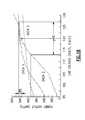
- Measured power as a function of line voltage is shown in Fig. 18 for three microwave ovens. Note the variation of the 500 watt number two oven indicating a 6% change in line voltage. The output power of the magnetron tube of the microwave oven has decreased from 500 watts to 375 watts. Also, note the non-linear relationship between line voltage and power output of the magnetron tube of the microwave oven. This non-linear relationship will produce wide swings in output power due to rather small changes in line voltage ( Microwave Cooking and Processing, Charles R. Buffler19xx ) .
- Microwave ovens presently in use employ various data entry mechanisms to input data into an oven control mechanism. These data entry mechanisms may be electrical and mechanical keyboards, card readers, light pens, wands, or the like.
- the control mechanism may be a computer or a microprocessor based controller. In general, the computer or controller has a basic input and output system (BIOS) associated with the input and output of data to and from the data entry mechanism.
- BIOS basic input and output system
- the user manually actuates the data entry mechanism to enter data relating to the type or mode of oven operation desired, i.e., bake, roast, re-heat, etc., as well as the length of the desired cooking time.
- Present microprocessor-based controllers are capable of receiving a substantial amount of complex information from their associated data entry mechanism. This requires the oven user or process stream designer to manually enter a substantial amount of information generally in a multi-step series of data inputs on a keyboard. This information could be entered by a magnetic card containing all of the required input data, but this type of format does not allow flexibility in changing the cooking instructions. Alternately, user input could recall a stored recipe specific to a particular food item.
- an item-specific stored recipe system is static and inherently limited to the universe of food items known to its author at its moment of creation. Such a system is closed to food items or processes created subsequent to its moment of manufacture, and, in any event, is a stored recipe system specific and limited to a single host microwave oven or process stream performance set.
- microwave ovens In the manufacture of consumer appliances, such as microwave ovens, it is advantageous to assume that the overall control requirements are nearly the same from model to model. This is done to reduce the cost of manufacture of the microwave ovens and make the repair of the ovens more economical.
- the functions of the microwave oven such as “auto cook,” “auto defrost” and a number of other cooking parameters associated with these functions vary from model to model, depending upon such factors as microwave cavity size, magnetron size, and other factors well known to practitioners in the art.
- a controller may be required to operate correctly in different microwave oven chassis having different oven cooking cavities. Typical oven cavity size ranges from about 0.5 cubic feet to about 2.0 cubic feet.
- the ovens also may vary in their effective magnetron power output.
- IEC 705 publication A well known phenomenon concerning the mass of a specimen is documented in the IEC 705 publication. This publication defines a procedure for determining the output power of a microwave oven. Following the IEC 705 procedure a 100 ml specimen of water is placed in a microwave oven. Power is applied to the specimen by the magnetron tube. The water boils at a specific power level in a given time period. The results of this test generated a classification of 800 watts for this particular microwave oven.
- Another test may be constructed following IEC 705 procedures.
- a specimen containing 250 ml of water is placed in the same microwave oven that was used to test the 100 ml specimen and power is applied to the specimen.
- Performing the same calculations as before the microwave oven now appears to be a 660 watt oven.
- This particular phenomenon clearly asserts the specimen mass has a pronounced effect on determination of the power rating of the microwave oven.
- Microwave power output can be controlled using two methods. The first is duty cycle control, and the second is amplitude modulation.
- duty cycle control the average output can be adjusted by operating the magnetron at full rated power, while switching its current on and off for portions of a time interval. The percentage of time that the current is on during the time interval is referred to as the "duty cycle.”
- the duty cycle of the microwave oven is generally implemented by electromechanical relays in conjunction with the controls of the microwave oven.
- the relays provide economies of scale for a manufacturing effort but they do not adequately provide competent electrical current switching.
- Magnetron power output is proportional to its cathode current.
- the cathode current is adjusted to control the instantaneous magnetron output.
- the instantaneous magnetron current is controlled either by varying the level of high voltage to the magnetron or by changing the magnetic field intensity in the magnetron.
- Another method of monitoring power output of the magnetron tube is to compare the monitored value of power to the power being delivered to the microwave oven by the power utility company. If these values do not compare after subtracting known losses, a compensation factor extracted from a lookup table has to be determined. This determined correction factor is mechanically or electronically applied to the magnetron tube. Applying this factor in this manner will increase or decrease the amount of power delivered to the magnetron tube. This is a self-defeating effort. If the magnetron tube power is too high the magnetron tube operating temperature will increase causing a decrease in efficiency, as discussed above. This results in a new compensation factor being applied to the magnetron tube power level. This cycle of applying correction factors and adjusting power levels will continue and the result of this effort will not correct the work performed on the specimen disposed within the microwave oven.
- Microprocessor based controllers are in widespread use in commercially available microwave ovens. Typically, the only difference in the command and control from one oven to the next is the programming stored within the controller's memory. It is quite feasible for control programs stored permanently in read only memory (ROM) to include parameters and instructions appropriate for a variety of oven models. Nevertheless, there remains the problem of identifying to the controller the particular oven and different oven or process stream functional characteristics of the host unit in which the controller resides. This particular problem is complicated over time by the introduction of newer models of microwave ovens. Newer models may contain newer microprocessors and different functional characteristic sets that require different operating instructions.
- Microwave ovens having compatible hardware can interact and share data. It has been possible in the past to exchange software between identical types of machines. To the contrary, most interactions between incompatible machines still involve little more than simple transfer of data files or the like. Software applications written for one microwave oven manufacturer or for one specific type of operating environment, however, cannot normally be ported or "transferred" to a system having different physical characteristics without being entirely rewritten. While much progress has made in developing techniques for exchanging data between incompatible machines, it has not been possible to exchange software application programs between different microwave ovens.
- European Patent Publication No. EP 0 029 483 discloses a power controlled microwave oven.
- the average food temperature is constantly derived during cooking, utilizing user entered data on the food category, the food's initial mass, and the measured input power to the magnetron.
- the average current and average peak voltage input to the magnetron are sensed and the absorbed power in the food is derived using the magnetron efficiency.
- the microprocessor sequentially derives the average food temperature as a function of cooking time using the entered food data, stored cooking coefficients previously determined by regression analysis, and the measured magnetron input power.
- the microprocessor derives the cooking time as a function of the average food temperature using the entered food data, a stored constant previously determined by regression analysis, and the measured magnetron input power.
- means are provided so that the user may select the final food temperature within the range from "rare” to " well done” and cooking continues until the desired final temperature is reached.
- Buck therefore, requires the entry of information on the food by the user, and uses a relatively complex program to determine the absorbed power and/or the temperature of the food.
- U.S. Patent No. 4,420,668 discloses a microwave oven whereby the power input to the cooking cavity is held at a predetermined, constant level. Available line power is measured through a winding or tap on the high voltage transformer secondary and the duty cycle of the magnetron power supply is adjusted to maintain a constant average power output.
- the present invention provides a machine for controlling the cooking of food or performance of thermodynamic process in any of a plethora of variously sized host microwave ovens.
- the present invention allows a host microwave oven to functionally operate by user independent predetermined codes.
- the controller has a central processing module, a memory module, and a plurality of input and output devices to send and receive data to and from the host microwave oven and the data entry mechanism.
- the predetermined codes provide the controller with instructions to command and control the host microwave oven, whereby the host microwave oven operates with user independent functional commands.
- the present invention provides for scaling the power level and/or the power level duration of the host microwave oven in response to performance degradation with age of the magnetron tube, process elements or variations of host unit in-situ elevation above mean sea level.
- a Work Manager controls the work performed on a specimen disposed within the confines of a Work Manager oven.
- the Work Manager is implemented by a controller.
- the controller has a memory for storing a software program or a plurality of data structures that provide commands and functions for the operation of the Work Manager.
- the controller also has at least one sensor operatively connected within the microwave oven for detecting the power supplied to the microwave oven magnetron tube, The sensor periodically transmits selected power data for processing.
- a predetermined code for a particular specimen is entered into the microwave oven.
- the predetermined code delineates a work characteristic particular to the selected specimen.
- the machine also receives power data periodically transmitted from the power sensor for processing.
- the power data and the predetermined code are processed by the Work Manager so that the microwave oven magnetron tube delivers the required work to the sample independent of power supplied to the microwave oven.
- the work manager controls the heating of a specimen in a microwave oven.
- the microwave oven comprises a cavity to receive the specimen, a microwave generating device for generating microwaves to heat the specimen, a power supply for providing operating power to the microwave generating device, and a sensor for measuring the operating power supplied to the microwave generating device.
- the work manager includes a user input device to allow a user to enter a predetermined code, the predetermined code comprising a plurality of numbers which correspond to an amount of energy that should be applied to a particular specimen to properly heat that particular specimen, and a controller, connected to the power supply for causing the power supply to provide operating power to the microwave generating device, connected to the sensor for determining the amount of energy applied to the specimen based upon the operating power supplied to the microwave generating device and the duration of application.of operating power, and connected to the user input device for receiving the predetermined code, the controller using the predetermined code to determine the predetermined energy amount to be applied, comparing that applied energy amount to that predetermined energy amount, and causing the power supply to stop providing operating power to the microwave generating device when the applied energy amount is at least approximately equal to the predetermined energy amount.
- the predetermined code encapsulates a profile indicative of the work to be performed on the specimen.
- the profile is selected from a group consisting of required specimen heating time(s), specimen geometry, heating power levels, specimen mass, the specimen material composition, and the like.
- an object of the present invention is to provide properly heating a specimen regardless of the power output capacity and power performance capability of the particular performing microwave oven.
- Another object is to manage the work performed on a specimen placed in a microwave oven so as to produce a heating or process result upon a specimen identical to the result produced within other differing microwave ovens of varied performance output capabilities, or like microwave ovens of differing age(s) or in situ elevation(s), all operating under widely varied supplied power conditions,
- interpretive BIOS machine 30, Fig. 3 is further illustrated in a block diagram 30, Fig. 5 .
- the architecture for interpretive BIOS machine 30, Fig. 5 is generally illustrated at 40, Fig. 6 .
- Architecture 40 is further illustrated at 40', Fig. 7 .
- Mode key 40b', Fig. 7 is further illustrated at 40b', Fig. 8 , containing elements 40b'a to 40b'f.
- Figs. 1-3 illustrate a typical microwave oven 10 used by households, restaurants, and other types of institutions that prepare and cook food.
- An example of a typical microwave oven would be a microwave oven manufactured by Cober Electronics, Inc., although any microprocessor, computer, or ASIC (Application Specific Integrated Circuit) controlled microwave oven or process stream is usable and operable in conjunction with the present invention.
- Microwave oven 10 for the purposes of illustration only, will host the present invention.
- Host microwave oven 10 has a data entry mechanism 10a, a display 10b, and a computer or controller with memory 10c, as shown in Fig. 3 .
- Data entry mechanism 10a may, if desired, be any type of data entry mechanism suitable for inputting data into host microwave oven 10.
- Data entry 10a mechanism may, if desired, transmit its data by serial or parallel format using any type of transmission medium such as, but not limited to, key pad entry, bar code reader, modem, computer or telephonic communications network or any other medium that allows transmissions of data.
- An example of data entry mechanism 10a would be a key pad part number KBD-KPX17P, manufactured by Alps, San Jose, CA.
- Data entry mechanism 10a for the purposes of illustration only will be discussed as a conventional touch responsive key pad known to those of ordinary skill in the art, although any data entry mechanism will function in conjunction with the present invention.
- Data entry mechanism 10a has at least one mode key. If desired, a plurality of mode keys may be implemented in conjunction with the present invention.
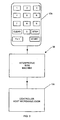
- key Fn 1, 10d, of data mechanism 10a will indicate the desire by the user of microwave oven 10 to enter a selected predetermined code 20, as shown in Fig. 2 .
- Selected code 20 represents a predetermined instruction set for heating or cooking a manufactured food item 20a. That predetermined code may, if desired, be listed in a recipe cook book 20b containing a plurality of predetermined codes.
- the cook book 20b may, if desired, contain selected codes along with conventional cooking instructions.
- Selected code 20 may, if desired, be comprised of at least one numeral, letter or symbol.
- An example of selected code 20 is a series of seven numbers.
- Manufactured food item 20a may require a plurality of processing steps to fully cook the foodstuffs properly.
- selected code 20 may represent any combination of process, steps of cooking, or cookbook recipe.
- the code 20 will be printed on or otherwise associated with the food packaging.
- a book of codes 20 can be assembled and provided to the user, most likely by the manufacturer of the food, a cookbook author, or process designer.
- the present invention is an interpretive BIOS machine illustrated generally at 30, as shown in Fig. 3 .
- Interpretive BIOS machine 30 is operatively disposed between the data entry mechanism 10a of the host microwave oven 10 and controller 10c.
- Interpretive BIOS machine 30 receives and processes selected code 20 and then outputs its interpreted and scaled instruction set to controller 10c.
- the interpreted instruction set provides host microwave oven 10 with user independent instructions for the cooking of food items desired by the user.
- the interpreted instruction set may contain one or a plurality of data fields that will compensate for variations in oven magnetron power, other similarly sized magnetron tube microwave oven performance variations, in-situ microwave oven elevation above sea level, aging of the host microwave oven, and the variation of cooking recipe requirements.
- interpretive BIOS machine 30 comprises a data input mechanism 30a, a microprocessor base controller 30b, and a data output mechanism 30c. As shown in Fig. 5 , interpretive BIOS machine 30 receives its operational power from power supply 10e.
- Data input mechanism 30a comprises a buffer that connects the output of data entry mechanism 10a of host microwave oven 10 to the input of controller 30b.
- An example of this buffer would be at least one Hex Non-inverting Buffer, MC14050b, manufactured by Motorola, Inc., Phoenix, Arizona. Controller 30b commands and controls all the operational functions of the present invention.
- controller 30b that may, if desired, be used in conjunction with the present invention is MC68HCl 1 manufactured by Motorola, Inc.
- This particular controller has an on-board memory used for storing data structures that provide controller 30b with instructions as to the operational features of the preset invention.
- Data emulator mechanism 30e is connected to controller 30b and receives encoded instructions from controller 30b. Data emulator 30e transforms those encoded instructions into suitable data for controller 10c.
- An example of data emulator would be a plurality or bank of operationally connected CD 5053 or CD 4051 devices.
- the output of data emulator 30e is connected to data output buffer 30.
- the output of mechanism 30c is connected to controller 10c.
- Interpretive BIOS machine 30 is completely buffered from host microwave oven 10 and is transparent to the user of host microwave oven 10.
- This buffering allows host microwave oven 10 to operate utilizing the present invention or to operate in the native mode, i.e., receiving data inputs directly from the user.
- the architecture for interpretive BIOS machine 30 is generally illustrated at 40, as shown in Fig. 6 .
- Architecture 40 contains a plurality of data structures that have their data determined in part by selected code 20 and in part by the interaction between respective data structures. These data structures provide controller 30b with instructions to command and control the host microwave oven 10 thereby allowing host microwave oven 10 to function independent of user commands.
- Mode Identifier data structure 40a receives its data from data entry mechanism 10a.
- Mode Identifier data structure 40a has data elements that determine if the interpretive BIOS machine is requested for activation or if the user of host microwave oven 10 desires to operate the oven in its native mode.
- Native mode once detected by Mode Identifier data structure 40a, operates without the assistance of interpretive BIOS machine 30.
- Mode Identifier data structure 40a passes the request for BIOS machine activation to Validator data structure 40b.
- Validator data structure 40b has elements that determine the validity of the input code 20 selected by the user. If Validator data structure 40b determines that selected code 20 is valid, data structure 40b will pass that result to Interpreter data structure 40c.
- Interpreter structure 40c Upon receiving Validator result, Interpreter structure 40c will transform user input code 20 into a data element set containing a plurality of data fields representing the requested duration and power level process instruction set of the selected code 20. Interpreter structure 40c may, if desired, transform user input code 20 into a data element set containing a plurality of data fields representing requested time duration and variable power level process instruction set of selected code 20.
- Scalar data structure 40d receives the data element set from Interpreter data structure 40c. Scalar data structure 40d transforms those data fields into suitable duration and power level requirements depending on the oven manufacturer's predetermined selection of scaling factor and additional user defined scale factor(s). Scaling factor(s) will be disclosed in greater detail hereinbelow.
- the scale duration and power data elements are encoded into a format that is understood by the host microwave oven 10.
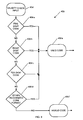
- Fig. 7 shows a logical flow diagram, indicated generally as 40'of the operational features of the interpretive BIOS machine 30 provided by architecture 40.
- An input data signal 40a' is received from host microwave oven 10. This input may, if desired, be accompanied by data generated by the user depressing the Fn 1 mode key 10d at least once. The mode of operation selected by the user is now determined. If Fn 1 10d is present the interpretive BIOS machine 30 has been selected. If Fn 110d is not present the native mode has been selected by the user and that selection 40e is transmitted to host microwave oven 10. The validity 406' of input data signal 30a' is now verified. If there is user error in input data signal 30a' the user will be notified by instructions that appear on display 10b.
- the validity check 40b' will default to a clear/stop function 40f and transmit that signal to the native mode of host microwave oven 10. If validity 40b' is verified, data signal 30a' is interpreted 40c' and transformed into data element set 40c' containing power levels and time duration(s). Data element set 40c' is then scaled at block 40d' to the operating characteristics of host microwave oven 10. Those scaled values 40d' are then transmitted at block 40g to host microwave oven 10 for implementation in the process of cooking food item 20a.
- Mode function 40a transmits an encoded data stream that is received by validated data structure 40b'. That data contains at least one data bit and may, if desired, contain a plurality of data bits. In the preferred embodiment, a five digit code at block 40b'a is transmitted by mode function at block 40a. This transmission is for illustrative purpose only. In fact, any number of digits may be transmitted. An eight digit code at block 40b'b, a ten digit code at block 40b'c, and other Interpretive BIOS Machine recognized code format(s) at block 40b'd may be transmitted. If the code at block 40b'e is valid it is transmitted to Interpreter data structure 40c. If the code at block 40b'f is invalid, a clear/stop function is transmitted to host microwave oven 10.
- Fig. 9 shows a more detailed diagram of Interpreter data structure 40c is illustrated at block 40c'.
- a validated code at block 40b'e is received and the code input is interpreted at block 40c'a as being a five, eight, or ten digit code. If the interpreted code is five digits at block 40c'b, the first digit n 1 is equal to or greater than one and equal to or less than nine and is interpreted by the BIOS to Power Level 1 (PL1), expressed as a percentage of the magnetron tube's total output capacity; i.e., 100%, 90%, and so forth. For a five digit code power level PL2 is equal to 0%.
- BIOS to Power Level 1 PL1
- PL1 duration is equal to the digit n2, n3, and n4 multiplied by one second.
- the five digit code is now interpreted and transformed into a new code representing specimen 20a's requirements for processing or cooking. This requirement for processing or cooking will vary depending on the specimen involved.
- This new five digit code is transmitted 40c'c to the scalar data structure 40d. If an eight digit code at block 40c'd is received by interpret code input at block 40c'a, digit n 1 and n2 are equal to or less than ninety-nine and equal to or greater than twenty.
- Power level PL1 is less than or equal to one hundred percent and equal to or greater than twenty percent.
- Power level PL2 is less than or equal to one hundred percent and equal to or greater than zero percent.
- PL1 is equal to or greater than PL2 at block 40c'e
- digits n3, n4, and n5 are multiplied by one second and are equal to time duration one.
- Duration for PL2 is equal to digit n6 and n7 multiplied by ten seconds.
- digits n3, n4, and n5 are multiplied by one second and are equal to power level two duration.
- Duration for PL1 is equal to digit n6 and n7 multiplied by ten seconds.
- Time duration three is equal to n8 multiplied by sixty seconds with power level PL3 equal to zero at block 40c'f.
- the eight digit code is now decoded and transformed into a new code representing the requirement for processing or cooking of specimen 20a.
- This new eight digit code is transmitted at block 40c'c to the scalar data structure 40d.
- a ten digit code is transformed in much the same way as the eighth digit code except for digit n9 that is multiplied by 60 seconds and is then equal to the time that has elapsed from the start process until pause one. Digit n10 is multiplied by sixty seconds and is then equal to the elapsed time since the end of pause one until pause two.
- Scalar data structure 40d has both manufacturer selected and user selected components. Scalar data structure 40d has its manufacturer selected universe of data empirically derived from the testing of a plurality or the universe of microwave ovens. A statistically derived sample of the universe of microwave ovens was selected. The sample ovens were each tested in an environmentally controlled and reproducible atmosphere to ensure repeatability of the test due to variations in ambient temperature, humidity, and atmospheric pressure. A control microwave oven was also tested to ensure accuracy and repeatability of the test. An example of the control microwave oven would be a microwave oven manufactured by Cober Electronics, Inc. The control microwave oven was tested to a control standard defined as a microwave oven containing a 1200 watt magnetron tube. The oven is placed in an environment maintained at an atmospheric pressure corresponding to that of an altitude of zero feet above mean sea level at a constant temperature of 20°C and an ambient humidity of 80%.
- the test comprised a series of testing iterations, the purpose of which was to characterize a microwave oven's (or thermodynamic, chemical, or physical process stream's) effective work production (i.e., work performed upon a sample calculable in watt-seconds) when heating samples of varying mass, composition, and container dimensions and geometry.
- a single test upon a sample of defined mass and composition and container geometry is herein described.
- the test comprised placing one liter of water of specifically known and reproducible chemical composition, molarity, molality, and dielectric properties in each microwave oven with a pyrometer disposed in each liter of water. The magnetron tube of a selected microwave oven was activated and the time to raise one liter of water one degree centigrade was recorded.
- the results of that test are generally illustrated in graph 60 in Fig. 10 .
- the median time range versus the universe of microwave ovens is illustrated at point 60a.
- the highest deviation from point 60a is illustrated at point 60b.
- the lowest deviation from point 60a is illustrated at point 60c.
- Points 60a, 60b, and 60c can be correlated to the highest power, measured in watts, of the magnetron tube used in each test. Conversely, points 60d, 60e, and 60f can be correlated to the lowest power, measured in watts, magnetron tube used in this test.
- a plurality of scalar values may now be determined from graph 60. Those scalar values are derived from the distance a select scalar point is to the median 60a, measured along the vertical axis of graph 60. Any number of points may, if desired, be disposed along any given vertical line extending from median line 60a. An example of that scalar value is scalar point 60g representing a value of .25 and scalar point 60h 4.0.
- the selected scalar values when applied to data element set 40c' transform the power and time duration contained within data element set 40c' into operating characteristics for microwave oven 10.
- a dynamic user-initiated BIOS calibration scalar component may be activated.
- the dynamic BIOS calibration updates in real time the power output operating and performance characteristics of the microwave oven 10 to the BIOS output scale level selected at the time of manufacture.
- a method to implement the calibration of microwave oven 10 is to depress Fn 1, 10d twice, whereupon display 10b will indicate the current BIOS operating level. By depressing Fn 1 10d simultaneously with a selected keypad number corresponding to the degree of BIOS, timed duration output scale level will increase desired scale value.
- pressing 1 causes a 5% BIOS output scale level increase
- pressing 3 causes a 10% BIOS output scale level increase
- the display will flash at least three times, indicating calibration is in process and the display 10b will now display the selected increase or decrease to the BIOS scaled value.
- Fn 1 10d is depressed along with the key zero.
- Another method of calibrating power level duration for microwave oven 10 is by depressing Fn 1 10d simultaneously with the start key 10e. This action will commence the National Postal Code ("zip code") BIOS calibration. Display 10a will flash the factory set BIOS National Postal Code. If this code is different than user's current postal code, the user may, if desired, enter their current National Postal Code.
- Interpretive BIOS machine 30 reads a stored National Postal Code corresponding to the elevation above mean sea level and the BIOS machine 30 performs a self calibration to adjust the power level duration to reflect the increase in elevation. The elevation above mean sea level may, if desired, be entered directly or a one digit direct input read from an Elevation Range-Performance Characteristic Table may be entered. In all cases interpretive BIOS machine 30 will perform a self calibration to increase or decrease the power level duration of microwave oven 10.
- the user of host microwave oven 10 may now cook food item 20a without regard for type of microwave oven employed, the power or aging of the magnetron tube of the selected microwave oven, or the in-situ elevation above mean sea level of the installed microwave oven or process stream.
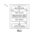
- FIG. 11 A top level illustration of the second embodiment of an interpretive BIOS machine 70 is illustrated in Fig. 11 .
- Interpretive BIOS machine 70 comprises a data input mechanism 30a, a microprocessor base controller 70a, and a data output mechanism 30c. As shown in Fig. 5 , interpretive BIOS machine 70 receives its operational power from power supply 10e. Data input mechanism 30a and data output mechanism 30c are interactively connected to controller 70 and host microwave oven 10 (discussed above). Controller 70a comprises in part a power monitor 70b, Fig. 12 , and Work Manager 70c, Fig. 12 . Controller 70a commands and controls all the operational functions of the second embodiment of the present invention.
- controller 70a that may, if desired, be used in conjunction with the second embodiment of the present invention is MC68HC11 manufactured by Motorola, Inc. This particular controller has an on-board memory used for storing a software program or data structure that provide controller 70a with instructions as to the operational features of the second embodiment of preset invention.
- Work Manager 70b is a software program or a plurality of data structures stored in the memory of controller 70a.
- the program provides the Work Manager 70c with instructions to interactively control the work function of the microwave oven.
- An example of this control would be the Work Manager 70b monitoring, correcting, adjusting, or modifying the work performed on a specimen.
- Another example would be the Work Manager collecting data from at least one sensor and transforming that data into commands for magnetron tube power to controller 70a.
- the controller 70a has a power monitor 70b connected to the power supplied to the microwave oven for detecting power consumed by the microwave oven.
- the power monitor 70b may, if desired, be a sensor connected to the magnetron tube of the microwave oven.
- the sensor may, if desired, monitor, collect or transmit data to the Work Manager 70c.
- the data may, if desired, be in a serial or parallel format.
- the data collected may, if desired be derived from voltage, current, power, power factor or any phase relationship between any of the aforementioned.
- An example of a typical power monitor measurement is voltage reading 70b' and current reading 70b", Fig. 13 . These two readings, 70b' and 70b", are transmitted to the Work Manager 70c for processing.
- the means of data transmission from the power monitor 70b to Work Manager 70c may be any ordinary transmission means known to those skilled in the art of data transmission.
- Power monitor 70b generated data is periodically transmitted to the Work Manager 70c or if desired the Work Manager 70c may request or poll any one or all of the power monitors to begin transmission of monitored data.
- Power monitor 70b may, if desired, receive data from the magnetron tube at different rates or duty cycles depending on manufacturing selection or design of the magnetron tube and/or the power monitor 70b.
- Data emulator mechanism 30e is operationally connected to and receives encoded instructions from controller 70a. Data emulator 30e transforms those encoded instructions into suitable data for controller 10c. An example of data emulator would be a plurality or bank of operationally connected CD 5053 or CD 4051 devices. The output of data emulator 30e is connected to data output buffer 30c. The output of mechanism 30c is connected to controller 10c.
- the second embodiment of the interpretive BIOS machine 70 is completely buffered from host microwave oven 10 and is transparent to the user of host microwave oven 10. This buffering allows host microwave oven 10 to operate utilizing the present invention or to operate in the native mode, i.e., receiving data inputs directly from the user.
- the Work Manager 70c receives power monitor 70b data structure and BIOS machine 70 data structure via controller 70a.
- BIOS machine 70 data structure delineates the work requirements to be performed on a specimen disposed within the confines of microwave oven 10.
- the work requirements were entered into microwave oven 10 by a user in the form of predetermined code 20.
- the work requirements of the specimen may if desired, be transparent to the user.
- the user simply extracts the predetermined code 20 from a specimen and enters predetermined code 20 into microwave oven 10.
- the Work Manager 70c processes the BIOS machine 70's data structure and the power monitor 70b's data structure.
- the processing of the data structures transforms them into command functions that contain data representing work expended on the specimen or work to be expended on the specimen.
- Controller 70a generates an instruction set comprising in part the command function provided by Work Manager 70c. Controller 70c then transmits this instruction set to microwave oven 10 to enable the proper work to be performed on the specimen.
- FIG. 13 A typical example of the operation of the power monitor 70b is illustrated in Figure 13 .
- a voltage 70b' signal and a current 70b" signal are received from magnetron tube of host microwave oven 10.
- the format and transmission of the signals may, if desired, be any convenient method known to those skilled in the art.
- an electronic circuit, Fig. 14 delineating the inner functionality of the power monitor is provided.
- Work manager 70c receives signals 70b' and 70b' and integrates them with respect to time thereby producing a plurality of selected work functions. Those work functions are accumulated at a selected rate to determine the actual work performed by the magnetron tube of microwave oven 10.
- the Work Manager 70c has received the suggested maximum time and power (work function) duration for BIOS machine 70. At 90% of the suggested work duration the accumulated work function is compared to the actual work performed on the specimen contained within microwave oven 10. If there is a true comparison (yes) no change is made to the work instructions provide to BIOS machine 70. If there is a false (no) result to the comparison a supplemental work function is derived.
- This supplemental work function adds or subtracts work from the suggested work function provided by BIOS machine 70.
- a control function is generated containing the adjusted work function.
- This control function is transmitted to the magnetron tube of microwave oven 10 wherein microwave oven 10 adjusts the work performed by its magnetron tube. This may, if desired, be a repeated process performed at any selected interval or duration.
- the duty cycle of microwave oven 10 may be mirrored by this process or timed in conjunction with any duty cycle of any microwave oven known in the art.
- a third embodiment of the present invention is a Code Maker tool generally illustrated as a block diagram at 80, Fig. 16 .
- Code Maker tool 80 provides the manufacturer of the specimen a convenient method to implement a predetermined code that may, if desired, be affixed to the specimen in any convenient manner known in the art.
- the specimen may, if desired, be represented as a plurality of unique descriptors that delineate unique characteristic of the specimen. Examples of some of those descriptors are type 80a, weight 80b, packing geometry 80c, and package dimensions. These are transmitted to and received by the Code Maker 80.
- Code maker 80 correlates these descriptors into a selected profile 80e that is displayed on a typical computer screen tool 90, Fig. 15 .
- the profile 80e provides all of the selected information and a suggested profile based on a history of all the aforementioned descriptors. Profile 80e is displayed on screen tool 90 for the convenience of the user.
- a language 80f is provided that has as its syntax all of the descriptors entered by the user and suggested by the Code Maker 80.
- the language expresses a computed symbol 80g that encapsulates all aforementioned descriptors.
- the symbol may, if desired, be any length, configuration, geometry, or symbol.
- a typical example of that symbol 80g comprises the digits 4-0-1.
- the code grammar that provides the metes and bounds for language 80f may comprise any format that enables descriptors, provided by a user, to be transformed into a symbol or symbols that are affixed to a specimen.
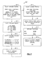
- An example of the code grammar that may, if desired, be used in conjunction with screen tool 90 is generally illustrated at 80f', Fig. 17 .
- An entree 80f 'a, with a weight of less then 175 grams, 80f 'b, is selected.
- the cooking profile 80f 'e is selected to be 'high none'. This profile is first selected and then displayed on screen tool 90.
- the specimen 80f 'f work duration is derived and displayed on screen tool 90 as symbol 401 80f 'g.
- a preferred mode of operation of the present invention is to provide controller 30b with a memory containing an embedded interpretive BIOS machine 30.
- Controller 30b is operatively disposed within microwave oven 10.
- Microwave oven 10 provides a data entry mechanism 10a that is operatively connected to oven 10 and controller 30b.
- the data entry mechanism 10a receives data from the user of microwave oven 10 and then transmits that data to the interpretive BIOS machine 30.
- Interpretive BIOS machine 30 selects a mode of operation from the received data.
- Interpretive BIOS machine 30 validates the selected mode of operation, interprets the received data into time duration and power level data, converts the time duration and power level data to selected BIOS power level(s) and power level time duration(s).
- the resulting process control instruction set is then scaled to the host oven or host process.
- Interpretive BIOS machine 30 then transmits the interpreted and scaled data to the microwave oven 10 whereupon the microwave oven operates as per BIOS interpreted and scaled time duration(s) and power level(s).
- a preferred mode of operation of the second embodiment of the present invention is to provide controller 70a with a memory containing an embedded interpretive BIOS machine 70.
- Controller 70a is operatively disposed within microwave oven 10.
- Microwave oven 10 provides a data entry mechanism 10a that is operatively connected to oven 10 and controller 70a.
- the data entry mechanism 10a receives the work requirements from the user of microwave oven 10 and then transmits those requirements to the interpretive BIOS machine 70.
- the Work Manager 70c disposed within and in communication with BIOS machine 70 receives signals from power monitor 70b.
- the Work Manager 70c interprets the work requirements received from BIOS machine 70 and the signals received from Power Monitor 70b.
- the Work Manager 70c processes the BIOS machine 70's work requirements and the power monitor 70b's signals.
- Controller 70a transforms the interpreted signals and requirements into command functions that contain data representing work expended on the specimen or work to be expended on the specimen. Controller 70a generates an instruction set comprising in part the command function provided by Work Manager 70c. Controller 70c then transmits this instruction set to microwave oven 10 to enable the proper work to be performed on the specimen.
- a preferred mode of operation of the third embodiment of the present invention is to provide a Code Maker tool 80 that provides the manufacturer of the specimen a convenient method to implement a predetermined code that may, if desired, be affixed to the specimen in any convenient manner known in the art.
- the specimen may, if desired, be represented as a plurality of unique descriptors that delineate unique characteristic of the specimen.
- Code maker 80 correlates these descriptors into a selected profile 80e that represents the work requirements of the specimen.
- the descriptors are formulated into a convenient arrangement of numbers or other symbols governed by the code grammar rules. That number or symbol (predetermined code) is then affixed to the specimen.
- the data entry mechanism 10a receives predetermined code from the user of microwave oven 10 and then transmits that predetermined code to the interpretive BIOS machine 70.
- the Work Manager 70c in communication with the BIOS machine 70 receives signals from power monitor 70b.
- the Work Manager 70c interprets the work requirements received from BIOS machine 70 and the signals received from Power Monitor 70b.
- the Work Manager 70c process the BIOS machine 70's work requirements and the power monitor 70b's signals. The processing transforms the interpreted signals and requirements into command functions that contain data representing work expended on the specimen or work to be expended on the specimen.
- Controller 70a generates an instruction set comprising in part the command function provided by Work Manager 70c. Controller 70c then transmits this instruction set to microwave oven 10 to enable the proper work to be performed on the specimen.
- the present invention may, if desired, be programmed in any suitable programming language known to those skill in the art.
- An example of that programming language is disclosed in C Programming Language, 2/e, Kernighan & Richtie, Prentice Hall, (1989 ).
- microwaves being the energy source employed
- other energy sources along the electromagnetic radiation spectrum can be employed by modifying or using different ovens or housings.
- ultraviolet, laser light, infrared, alpha, beta, gamma, or x-ray radiation, or combinations thereof, can be employed. It would be a matter of developing specific profiles for the items to be "processed" by the radiation.
- Such items are not limited to food, but may also include, but are not limited to, painted articles where the paint is to be cured by infrared or UV light, coatings which may be cured by UV light, polymerization by UV light, irradiation of objects by radioactive energy beams, cutting, warming or melting of objects by infrared or laser light, and the like.
- the present invention can be used to permit such profile to be entered into a BIOS or machine which will accept and convert the data into operational signals which control, via a microprocessor or similar controller, the actuation, direction and characteristics of the energy source with respect to the article to be processed.
- the respective energy processing properties can be determined with reasonable predictability to develop standard codes for processing standard items. Such items can then be predictably and repeatably processed to reduce random variation in result and improve quality control and quality assurance.
Landscapes
- Physics & Mathematics (AREA)
- Electromagnetism (AREA)
- Engineering & Computer Science (AREA)
- Human Computer Interaction (AREA)
- General Physics & Mathematics (AREA)
- Automation & Control Theory (AREA)
- Electric Ovens (AREA)
- Analysing Materials By The Use Of Radiation (AREA)
- Electrotherapy Devices (AREA)
Abstract
Description
- The invention is directed to a work manager that controls the work performed on a specimen disposed within the confines of a microwave oven.
- A microwave oven cooks food by bombarding the food with electromagnetic waves which cause molecules in the food to vibrate billions of times per second. Heat is created when dipolar molecules (such as water) vibrate back and forth aligning themselves with the electric field or when the ions migrate in response to the electric field.
- The vibrations cause heat by friction, although only at a depth of about I to 1.5 inches. Heat transfer properties of food continue the process of cooking by transmitting heat to areas of the cooking food that are relatively cool in comparison to the areas that have been heated by the electromagnetic waves.
- Convenience of the microwave oven and reduced preparation time are key factors in the success of the microwave oven. Taste and quality of the food after being cooked in the microwave oven were at times lacking with early models because of inconsistent voltage management, inaccurately controlled magnetron tubes, and imperfect software control. Convenience was also lacking because as the demand for microwavable food increased so did the complexity of instructions for cooking that food. Imprecision of cooking instructions was fostered by among other factors the differing user interfaces and operational characteristics of dissimilar and similar sized microwave ovens and allied microwave oven operational control and user interface disparities. Consumers want the convenience of microwave cooking but do not want to constantly refer back to a package to enter and re-enter multistep instructions into a microwave oven to obtain cooked food, and still, after all their efforts receive sub-standard cooking results due to microwave oven operational and performance variances.
- Because of more active lifestyles and less time spent in the kitchen, consumer demand for microwavable products is increasing along with the demand for a microwave oven that does not require a plurality of instructions to cook food, or different instructions for the same food item for different size and/or manufactured microwave ovens. Complicating the issue of product demand and usable microwave ovens is the wide variance in magnetron output power, performance variances, and user control interfaces now prevalent in the available universe of microwave ovens. A food product that may cook very well in a 1200 watt oven may take three times as long in an oven which can only provide 600 watts of power. Moreover, the user interface from microwave ovens of one manufacturer to another is often markedly different and non-intuitive.
- Further complicating the issue of the wide variation in magnetron tube output power is the local utility (power company) that supplies power to the microwave oven of the user. Utility companies are often unable to balance adequately user demand for power with available power generation capability. The effect of power fluctuations on a microwave oven are numerous. In particular, the suggested cooking instructions for a particular food becomes meaningless. An example of this would be a power fluctuation of 6% by the public utility or power generation source for a brief period. The results of the degradation of power supplied to the microwave oven will be food that is undercooked. This may very well result in health hazards to the consumer of the food cooked in a microwave oven if bacteria is not killed by sufficient cooking. The sensitivity of output power to line voltage is a source of concern to the microwave oven food developer as well as the consumer. Measured power as a function of line voltage is shown in
Fig. 18 for three microwave ovens. Note the variation of the 500 watt number two oven indicating a 6% change in line voltage. The output power of the magnetron tube of the microwave oven has decreased from 500 watts to 375 watts. Also, note the non-linear relationship between line voltage and power output of the magnetron tube of the microwave oven. This non-linear relationship will produce wide swings in output power due to rather small changes in line voltage (Microwave Cooking and Processing, Charles R. Buffler19xx). - Microwave ovens presently in use employ various data entry mechanisms to input data into an oven control mechanism. These data entry mechanisms may be electrical and mechanical keyboards, card readers, light pens, wands, or the like. The control mechanism may be a computer or a microprocessor based controller. In general, the computer or controller has a basic input and output system (BIOS) associated with the input and output of data to and from the data entry mechanism. In such microwave ovens the user manually actuates the data entry mechanism to enter data relating to the type or mode of oven operation desired, i.e., bake, roast, re-heat, etc., as well as the length of the desired cooking time.
- Present microprocessor-based controllers are capable of receiving a substantial amount of complex information from their associated data entry mechanism. This requires the oven user or process stream designer to manually enter a substantial amount of information generally in a multi-step series of data inputs on a keyboard. This information could be entered by a magnetic card containing all of the required input data, but this type of format does not allow flexibility in changing the cooking instructions. Alternately, user input could recall a stored recipe specific to a particular food item. Those familiar with the art can see that an item-specific stored recipe system is static and inherently limited to the universe of food items known to its author at its moment of creation. Such a system is closed to food items or processes created subsequent to its moment of manufacture, and, in any event, is a stored recipe system specific and limited to a single host microwave oven or process stream performance set.
- In the manufacture of consumer appliances, such as microwave ovens, it is advantageous to assume that the overall control requirements are nearly the same from model to model. This is done to reduce the cost of manufacture of the microwave ovens and make the repair of the ovens more economical. The functions of the microwave oven such as "auto cook," "auto defrost" and a number of other cooking parameters associated with these functions vary from model to model, depending upon such factors as microwave cavity size, magnetron size, and other factors well known to practitioners in the art. Thus a controller may be required to operate correctly in different microwave oven chassis having different oven cooking cavities. Typical oven cavity size ranges from about 0.5 cubic feet to about 2.0 cubic feet. The ovens also may vary in their effective magnetron power output.
- A well known phenomenon concerning the mass of a specimen is documented in the IEC 705 publication. This publication defines a procedure for determining the output power of a microwave oven. Following the IEC 705 procedure a 100 ml specimen of water is placed in a microwave oven. Power is applied to the specimen by the magnetron tube. The water boils at a specific power level in a given time period. The results of this test generated a classification of 800 watts for this particular microwave oven.
- To further explain the phenomenon another test may be constructed following IEC 705 procedures. A specimen containing 250 ml of water is placed in the same microwave oven that was used to test the 100 ml specimen and power is applied to the specimen. Performing the same calculations as before the microwave oven now appears to be a 660 watt oven. This particular phenomenon clearly asserts the specimen mass has a pronounced effect on determination of the power rating of the microwave oven.
- Microwave power output can be controlled using two methods. The first is duty cycle control, and the second is amplitude modulation. In duty cycle control, the average output can be adjusted by operating the magnetron at full rated power, while switching its current on and off for portions of a time interval. The percentage of time that the current is on during the time interval is referred to as the "duty cycle."
- The duty cycle of the microwave oven is generally implemented by electromechanical relays in conjunction with the controls of the microwave oven. The relays provide economies of scale for a manufacturing effort but they do not adequately provide competent electrical current switching.
- Magnetron power output is proportional to its cathode current. In amplitude modulation, the cathode current is adjusted to control the instantaneous magnetron output. The instantaneous magnetron current is controlled either by varying the level of high voltage to the magnetron or by changing the magnetic field intensity in the magnetron.
- Attempts in the past have been made to monitor magnetron tube power and compensate for the fluctuations in power produced by the magnetron tube. It is well known in the art that when the operating temperature of a magnetron tube increases the power produced decreases. The operating temperature of the magnetron tube will increase due to normal operation. The heat produced by the specimen contained within the microwave oven having work performed thereon will also increase the temperature of the magnetron tube. The specimen does not consume 100% of the power generated by the magnetron tube; therefore, some of that power will be radiated outwardly from the specimen in the form of heat. Given the close proximity of the magnetron tube to the specimen the magnetron tube operating temperature will undoubtedly increase.
- Monitoring the output of the microwave oven and then increasing input power to raise the power output of the magnetron tube is a self-defeating effort. As more power is supplied to the magnetron tube the power output of the magnetron tube increases, but the efficiency of the magnetron tube is decreases, thereby increasing the operating temperature. This means the input power should be increased to compensate for the decrease in output power. This process will continue until a maximum input power is achieved thereby saturating the magnetron tube and further decreasing efficiency of the magnetron tube.
- Another method of monitoring power output of the magnetron tube is to compare the monitored value of power to the power being delivered to the microwave oven by the power utility company. If these values do not compare after subtracting known losses, a compensation factor extracted from a lookup table has to be determined. This determined correction factor is mechanically or electronically applied to the magnetron tube. Applying this factor in this manner will increase or decrease the amount of power delivered to the magnetron tube. This is a self-defeating effort. If the magnetron tube power is too high the magnetron tube operating temperature will increase causing a decrease in efficiency, as discussed above. This results in a new compensation factor being applied to the magnetron tube power level. This cycle of applying correction factors and adjusting power levels will continue and the result of this effort will not correct the work performed on the specimen disposed within the microwave oven.
- It is a well known principle of physics that when a force does work on an object it must increase the energy of that object by a like amount (or decrease if the work is negative). When an object loses energy of any form, it must experience a like increase in energy of some other form, or it must do a like amount of work. Power discussed herein is the time rate of doing work. Power is expressed as an equation: Work = Power x time.
- Microprocessor based controllers are in widespread use in commercially available microwave ovens. Typically, the only difference in the command and control from one oven to the next is the programming stored within the controller's memory. It is quite feasible for control programs stored permanently in read only memory (ROM) to include parameters and instructions appropriate for a variety of oven models. Nevertheless, there remains the problem of identifying to the controller the particular oven and different oven or process stream functional characteristics of the host unit in which the controller resides. This particular problem is complicated over time by the introduction of newer models of microwave ovens. Newer models may contain newer microprocessors and different functional characteristic sets that require different operating instructions.
- Microwave ovens having compatible hardware can interact and share data. It has been possible in the past to exchange software between identical types of machines. To the contrary, most interactions between incompatible machines still involve little more than simple transfer of data files or the like. Software applications written for one microwave oven manufacturer or for one specific type of operating environment, however, cannot normally be ported or "transferred" to a system having different physical characteristics without being entirely rewritten. While much progress has made in developing techniques for exchanging data between incompatible machines, it has not been possible to exchange software application programs between different microwave ovens.
- Data presented in the form of recipe instructions that offer static cooking conditions differ on characteristics of the material to be cooked. The material inherently varies in dielectric property, relative dielectric constant, and loss factor. These properties govern both heating rate and uniformity, the latter being influenced by the depth of penetration of the microwave energy. Accordingly, conventional fixed cooking program functions do not allow the entry of data concerning the conditions of the material to be cooked into memory of the computer or controller of a microwave oven. As a result two materials would be cooked under the same cooking conditions in spite of having different material characteristics and cooking profiles. This causes an undesirable cooking operation.
- European Patent Publication No.
EP 0 029 483 (Buck -
U.S. Patent No. 4,420,668 (Larson ) discloses a microwave oven whereby the power input to the cooking cavity is held at a predetermined, constant level. Available line power is measured through a winding or tap on the high voltage transformer secondary and the duty cycle of the magnetron power supply is adjusted to maintain a constant average power output. - It would be desirable to have a microwave oven or process control system that could accept pre-defined user entered programming information that could be interpreted and scaled to varying magnetron performance or process performance level(s) and power level duration(s) specific to a particular host unit. As the result of a single user entered pre-defined code, the final end result of a process performed for a particular item would be independent of and produce identical results upon the item regardless of the functional operating characteristics of any particular host microwave oven or process stream into which the user entered pre-defined code is input.
- The present invention provides a machine for controlling the cooking of food or performance of thermodynamic process in any of a plethora of variously sized host microwave ovens. The present invention allows a host microwave oven to functionally operate by user independent predetermined codes. The controller has a central processing module, a memory module, and a plurality of input and output devices to send and receive data to and from the host microwave oven and the data entry mechanism.
- The predetermined codes provide the controller with instructions to command and control the host microwave oven, whereby the host microwave oven operates with user independent functional commands.
- The present invention provides for scaling the power level and/or the power level duration of the host microwave oven in response to performance degradation with age of the magnetron tube, process elements or variations of host unit in-situ elevation above mean sea level.
- A Work Manager controls the work performed on a specimen disposed within the confines of a Work Manager oven. The Work Manager is implemented by a controller. The controller has a memory for storing a software program or a plurality of data structures that provide commands and functions for the operation of the Work Manager. The controller also has at least one sensor operatively connected within the microwave oven for detecting the power supplied to the microwave oven magnetron tube, The sensor periodically transmits selected power data for processing. A predetermined code for a particular specimen is entered into the microwave oven. The predetermined code delineates a work characteristic particular to the selected specimen. The machine also receives power data periodically transmitted from the power sensor for processing. The power data and the predetermined code are processed by the Work Manager so that the microwave oven magnetron tube delivers the required work to the sample independent of power supplied to the microwave oven.
- The work manager controls the heating of a specimen in a microwave oven. The microwave oven comprises a cavity to receive the specimen, a microwave generating device for generating microwaves to heat the specimen, a power supply for providing operating power to the microwave generating device, and a sensor for measuring the operating power supplied to the microwave generating device. The work manager includes a user input device to allow a user to enter a predetermined code, the predetermined code comprising a plurality of numbers which correspond to an amount of energy that should be applied to a particular specimen to properly heat that particular specimen, and a controller, connected to the power supply for causing the power supply to provide operating power to the microwave generating device, connected to the sensor for determining the amount of energy applied to the specimen based upon the operating power supplied to the microwave generating device and the duration of application.of operating power, and connected to the user input device for receiving the predetermined code, the controller using the predetermined code to determine the predetermined energy amount to be applied, comparing that applied energy amount to that predetermined energy amount, and causing the power supply to stop providing operating power to the microwave generating device when the applied energy amount is at least approximately equal to the predetermined energy amount.
- The predetermined code encapsulates a profile indicative of the work to be performed on the specimen. The profile is selected from a group consisting of required specimen heating time(s), specimen geometry, heating power levels, specimen mass, the specimen material composition, and the like.
- Accordingly, an object of the present invention is to provide properly heating a specimen regardless of the power output capacity and power performance capability of the particular performing microwave oven.
- Another object is to manage the work performed on a specimen placed in a microwave oven so as to produce a heating or process result upon a specimen identical to the result produced within other differing microwave ovens of varied performance output capabilities, or like microwave ovens of differing age(s) or in situ elevation(s), all operating under widely varied supplied power conditions,
- Other objects, features and advantages of the present invention will become apparent upon reading the following detailed description of embodiments of the invention, when taken in conjunction with the accompanying drawings and the appended claims.
- The invention is illustrated in the drawings in which like reference characters designate the same or similar parts throughout the figures of which:
-
Fig. 1 illustrates a schematic view of a host microwave oven, -
Fig. 2 illustrates a block diagram showing a symbolic code being entered into the keypad ofFig. 1 , -
Fig. 3 illustrates the present invention disposed intermediate the key pad ofFig. 1 and the controller of the host microwave oven, -
Fig. 4 illustrates a block diagram of an interpretive BIOS machine, -
Fig. 5 illustrates a block diagram of the interpretive BIOS machine connected to the host microwave oven, -
Fig. 6 illustrates the architecture for interpretive BIOS machine ofFig. 5 , -
Fig. 7 illustrates a flow diagram ofFig. 6 , -
Fig. 8 illustrate a flow diagram of the validator ofFig. 6 , -
Fig. 9 illustrates a flow diagram of the interpreter ofFig. 6 , and -
Fig. 10 is a test result graph, -
Fig. 11 illustrates a block diagram of a second embodiment of an interpretive BIOS machine, -
Fig. 12 illustrates a block diagram of the interpretive BIOS machine with a Work Manager connected to the host microwave oven, -
Fig. 13 illustrates the Work Manager ofFig. 12 , -
Fig. 14 illustrates a typical electrical circuit for monitoring power ofFig. 13 , -
Fig. 15 illustrates a Code Maker computer screen tool for capturing the work requirements of a specimen, -
Fig. 16 illustrates a block diagram of a Code Maker a third embodiment of an interpretive BIOS machine, -
Fig. 17 illustrates an operational block diagram for predetermining a code, -
Fig. 18 illustrates line voltage versus power output to a microwave oven. - The interdependence of the element numbers of the drawings has been referenced above and for the convenience of the reader will be reiterated here by citing an example of the flow of element numbers to drawings. This example is intended for illustrative purpose only:
interpretive BIOS machine 30,Fig. 3 , is further illustrated in a block diagram 30,Fig. 5 . The architecture forinterpretive BIOS machine 30,Fig. 5 , is generally illustrated at 40,Fig. 6 .Architecture 40 is further illustrated at 40',Fig. 7 . Mode key 40b',Fig. 7 , is further illustrated at 40b',Fig. 8 , containing elements 40b'a to 40b'f. -
Figs. 1-3 illustrate atypical microwave oven 10 used by households, restaurants, and other types of institutions that prepare and cook food. An example of a typical microwave oven would be a microwave oven manufactured by Cober Electronics, Inc., although any microprocessor, computer, or ASIC (Application Specific Integrated Circuit) controlled microwave oven or process stream is usable and operable in conjunction with the present invention.Microwave oven 10, for the purposes of illustration only, will host the present invention. -
Host microwave oven 10 has adata entry mechanism 10a, adisplay 10b, and a computer or controller withmemory 10c, as shown inFig. 3 .Data entry mechanism 10a may, if desired, be any type of data entry mechanism suitable for inputting data intohost microwave oven 10.Data entry 10a mechanism may, if desired, transmit its data by serial or parallel format using any type of transmission medium such as, but not limited to, key pad entry, bar code reader, modem, computer or telephonic communications network or any other medium that allows transmissions of data. An example ofdata entry mechanism 10a would be a key pad part number KBD-KPX17P, manufactured by Alps, San Jose, CA.Data entry mechanism 10a for the purposes of illustration only will be discussed as a conventional touch responsive key pad known to those of ordinary skill in the art, although any data entry mechanism will function in conjunction with the present invention.Data entry mechanism 10a has at least one mode key. If desired, a plurality of mode keys may be implemented in conjunction with the present invention. For the purpose of illustration only,key Fn data mechanism 10a will indicate the desire by the user ofmicrowave oven 10 to enter a selectedpredetermined code 20, as shown inFig. 2 . Selectedcode 20 represents a predetermined instruction set for heating or cooking a manufacturedfood item 20a. That predetermined code may, if desired, be listed in arecipe cook book 20b containing a plurality of predetermined codes. Thecook book 20b may, if desired, contain selected codes along with conventional cooking instructions. Selectedcode 20 may, if desired, be comprised of at least one numeral, letter or symbol. An example of selectedcode 20 is a series of seven numbers. Manufacturedfood item 20a may require a plurality of processing steps to fully cook the foodstuffs properly. In this particular case selectedcode 20 may represent any combination of process, steps of cooking, or cookbook recipe. Ordinarily, thecode 20 will be printed on or otherwise associated with the food packaging. Alternatively, a book ofcodes 20 can be assembled and provided to the user, most likely by the manufacturer of the food, a cookbook author, or process designer. - The present invention is an interpretive BIOS machine illustrated generally at 30, as shown in
Fig. 3 .Interpretive BIOS machine 30 is operatively disposed between thedata entry mechanism 10a of thehost microwave oven 10 andcontroller 10c.Interpretive BIOS machine 30 receives and processes selectedcode 20 and then outputs its interpreted and scaled instruction set tocontroller 10c. The interpreted instruction set provideshost microwave oven 10 with user independent instructions for the cooking of food items desired by the user. The interpreted instruction set may contain one or a plurality of data fields that will compensate for variations in oven magnetron power, other similarly sized magnetron tube microwave oven performance variations, in-situ microwave oven elevation above sea level, aging of the host microwave oven, and the variation of cooking recipe requirements. - A top level illustration of
interpretive BIOS machine 30 is shown inFig. 4 .Interpretive BIOS machine 30 comprises adata input mechanism 30a, amicroprocessor base controller 30b, and adata output mechanism 30c. As shown inFig. 5 ,interpretive BIOS machine 30 receives its operational power frompower supply 10e.Data input mechanism 30a comprises a buffer that connects the output ofdata entry mechanism 10a ofhost microwave oven 10 to the input ofcontroller 30b. An example of this buffer would be at least one Hex Non-inverting Buffer, MC14050b, manufactured by Motorola, Inc., Phoenix, Arizona.Controller 30b commands and controls all the operational functions of the present invention. An example ofcontroller 30b that may, if desired, be used in conjunction with the present invention isMC68HCl 1 manufactured by Motorola, Inc. This particular controller has an on-board memory used for storing data structures that providecontroller 30b with instructions as to the operational features of the preset invention.Data emulator mechanism 30e is connected tocontroller 30b and receives encoded instructions fromcontroller 30b.Data emulator 30e transforms those encoded instructions into suitable data forcontroller 10c. An example of data emulator would be a plurality or bank of operationally connected CD 5053 or CD 4051 devices. The output ofdata emulator 30e is connected todata output buffer 30. The output ofmechanism 30c is connected tocontroller 10c.Interpretive BIOS machine 30 is completely buffered fromhost microwave oven 10 and is transparent to the user ofhost microwave oven 10. This buffering allowshost microwave oven 10 to operate utilizing the present invention or to operate in the native mode, i.e., receiving data inputs directly from the user. The architecture forinterpretive BIOS machine 30 is generally illustrated at 40, as shown inFig. 6 .Architecture 40 contains a plurality of data structures that have their data determined in part by selectedcode 20 and in part by the interaction between respective data structures. These data structures providecontroller 30b with instructions to command and control thehost microwave oven 10 thereby allowinghost microwave oven 10 to function independent of user commands. - Mode
Identifier data structure 40a, as shown inFig. 6 , receives its data fromdata entry mechanism 10a. ModeIdentifier data structure 40a has data elements that determine if the interpretive BIOS machine is requested for activation or if the user ofhost microwave oven 10 desires to operate the oven in its native mode. Native mode, once detected by ModeIdentifier data structure 40a, operates without the assistance ofinterpretive BIOS machine 30. ModeIdentifier data structure 40a passes the request for BIOS machine activation toValidator data structure 40b.Validator data structure 40b has elements that determine the validity of theinput code 20 selected by the user. IfValidator data structure 40b determines that selectedcode 20 is valid,data structure 40b will pass that result toInterpreter data structure 40c. Upon receiving Validator result,Interpreter structure 40c will transformuser input code 20 into a data element set containing a plurality of data fields representing the requested duration and power level process instruction set of the selectedcode 20.Interpreter structure 40c may, if desired, transformuser input code 20 into a data element set containing a plurality of data fields representing requested time duration and variable power level process instruction set of selectedcode 20. -
Scalar data structure 40d receives the data element set fromInterpreter data structure 40c.Scalar data structure 40d transforms those data fields into suitable duration and power level requirements depending on the oven manufacturer's predetermined selection of scaling factor and additional user defined scale factor(s). Scaling factor(s) will be disclosed in greater detail hereinbelow. The scale duration and power data elements are encoded into a format that is understood by thehost microwave oven 10. -
Fig. 7 shows a logical flow diagram, indicated generally as 40'of the operational features of theinterpretive BIOS machine 30 provided byarchitecture 40. An input data signal 40a' is received fromhost microwave oven 10. This input may, if desired, be accompanied by data generated by the user depressing theFn 1 mode key 10d at least once. The mode of operation selected by the user is now determined. IfFn 1 10d is present theinterpretive BIOS machine 30 has been selected. If Fn 110d is not present the native mode has been selected by the user and thatselection 40e is transmitted to hostmicrowave oven 10. The validity 406' of input data signal 30a' is now verified. If there is user error in input data signal 30a' the user will be notified by instructions that appear ondisplay 10b. If inaccuracies indata signal 30a' cannot be resolved, thevalidity check 40b' will default to a clear/stop function 40f and transmit that signal to the native mode ofhost microwave oven 10. Ifvalidity 40b' is verified, data signal 30a' is interpreted 40c' and transformed into data element set 40c' containing power levels and time duration(s). Data element set 40c' is then scaled atblock 40d' to the operating characteristics ofhost microwave oven 10. Those scaledvalues 40d' are then transmitted atblock 40g to hostmicrowave oven 10 for implementation in the process of cookingfood item 20a. -
Fig. 8 shows a more detailed diagram 40b' ofvalidation data structure 40b.Mode function 40a transmits an encoded data stream that is received by validateddata structure 40b'. That data contains at least one data bit and may, if desired, contain a plurality of data bits. In the preferred embodiment, a five digit code at block 40b'a is transmitted by mode function atblock 40a. This transmission is for illustrative purpose only. In fact, any number of digits may be transmitted. An eight digit code at block 40b'b, a ten digit code at block 40b'c, and other Interpretive BIOS Machine recognized code format(s) atblock 40b'd may be transmitted. If the code at block 40b'e is valid it is transmitted toInterpreter data structure 40c. If the code at block 40b'f is invalid, a clear/stop function is transmitted to hostmicrowave oven 10. -
Fig. 9 shows a more detailed diagram ofInterpreter data structure 40c is illustrated atblock 40c'. A validated code at block 40b'e is received and the code input is interpreted at block 40c'a as being a five, eight, or ten digit code. If the interpreted code is five digits at block 40c'b, thefirst digit n 1 is equal to or greater than one and equal to or less than nine and is interpreted by the BIOS to Power Level 1 (PL1), expressed as a percentage of the magnetron tube's total output capacity; i.e., 100%, 90%, and so forth. For a five digit code power level PL2 is equal to 0%. PL1 duration is equal to the digit n2, n3, and n4 multiplied by one second. The five digit code is now interpreted and transformed into a newcode representing specimen 20a's requirements for processing or cooking. This requirement for processing or cooking will vary depending on the specimen involved. This new five digit code is transmitted 40c'c to thescalar data structure 40d. If an eight digit code atblock 40c'd is received by interpret code input at block 40c'a,digit n 1 and n2 are equal to or less than ninety-nine and equal to or greater than twenty. Power level PL1 is less than or equal to one hundred percent and equal to or greater than twenty percent. Power level PL2 is less than or equal to one hundred percent and equal to or greater than zero percent. If PL1 is equal to or greater than PL2 at block 40c'e, digits n3, n4, and n5 are multiplied by one second and are equal to time duration one. Duration for PL2 is equal to digit n6 and n7 multiplied by ten seconds. If PL2 is equal to or greater than PL1 40c'e, digits n3, n4, and n5 are multiplied by one second and are equal to power level two duration. Duration for PL1 is equal to digit n6 and n7 multiplied by ten seconds. Time duration three is equal to n8 multiplied by sixty seconds with power level PL3 equal to zero at block 40c'f. The eight digit code is now decoded and transformed into a new code representing the requirement for processing or cooking ofspecimen 20a. This new eight digit code is transmitted at block 40c'c to thescalar data structure 40d. A ten digit code is transformed in much the same way as the eighth digit code except for digit n9 that is multiplied by 60 seconds and is then equal to the time that has elapsed from the start process until pause one. Digit n10 is multiplied by sixty seconds and is then equal to the elapsed time since the end of pause one until pause two. (Enablement of pause one and pause two allows for user intervention and intermediate user actions during the processing or cooking sequence.) The user determines when the pause is complete and the control program is to resume by pressing Fn 1-10d. Like the five and eight digit code the ten digit code is transmitted toscalar data structure 40d. -
Scalar data structure 40d has both manufacturer selected and user selected components.Scalar data structure 40d has its manufacturer selected universe of data empirically derived from the testing of a plurality or the universe of microwave ovens. A statistically derived sample of the universe of microwave ovens was selected. The sample ovens were each tested in an environmentally controlled and reproducible atmosphere to ensure repeatability of the test due to variations in ambient temperature, humidity, and atmospheric pressure. A control microwave oven was also tested to ensure accuracy and repeatability of the test. An example of the control microwave oven would be a microwave oven manufactured by Cober Electronics, Inc. The control microwave oven was tested to a control standard defined as a microwave oven containing a 1200 watt magnetron tube. The oven is placed in an environment maintained at an atmospheric pressure corresponding to that of an altitude of zero feet above mean sea level at a constant temperature of 20°C and an ambient humidity of 80%. - The test comprised a series of testing iterations, the purpose of which was to characterize a microwave oven's (or thermodynamic, chemical, or physical process stream's) effective work production (i.e., work performed upon a sample calculable in watt-seconds) when heating samples of varying mass, composition, and container dimensions and geometry. A single test upon a sample of defined mass and composition and container geometry is herein described. The test comprised placing one liter of water of specifically known and reproducible chemical composition, molarity, molality, and dielectric properties in each microwave oven with a pyrometer disposed in each liter of water. The magnetron tube of a selected microwave oven was activated and the time to raise one liter of water one degree centigrade was recorded. The results of that test are generally illustrated in
graph 60 inFig. 10 . The median time range versus the universe of microwave ovens is illustrated atpoint 60a. The highest deviation frompoint 60a is illustrated at point 60b. The lowest deviation frompoint 60a is illustrated atpoint 60c. -
Points - A plurality of scalar values may now be determined from
graph 60. Those scalar values are derived from the distance a select scalar point is to the median 60a, measured along the vertical axis ofgraph 60. Any number of points may, if desired, be disposed along any given vertical line extending frommedian line 60a. An example of that scalar value isscalar point 60g representing a value of .25 andscalar point 60h 4.0. The selected scalar values when applied to data element set 40c' transform the power and time duration contained within data element set 40c' into operating characteristics formicrowave oven 10. - To compensate for the magnetron tube (and other components) as well as the power level output degradation of
microwave oven 10 over the useful life of the oven, a dynamic user-initiated BIOS calibration scalar component may be activated. The dynamic BIOS calibration updates in real time the power output operating and performance characteristics of themicrowave oven 10 to the BIOS output scale level selected at the time of manufacture. A method to implement the calibration ofmicrowave oven 10 is to depressFn display 10b will indicate the current BIOS operating level. By depressingFn 1 10d simultaneously with a selected keypad number corresponding to the degree of BIOS, timed duration output scale level will increase desired scale value. An example of this would be pressing 1 causes a 5% BIOS output scale level increase, pressing 3 causes a 10% BIOS output scale level increase, etc. The display will flash at least three times, indicating calibration is in process and thedisplay 10b will now display the selected increase or decrease to the BIOS scaled value. To reset the BIOS scaled value to the original value,Fn 1 10d is depressed along with the key zero. - Another method of calibrating power level duration for
microwave oven 10 is by depressingFn 1 10d simultaneously with the start key 10e. This action will commence the National Postal Code ("zip code") BIOS calibration.Display 10a will flash the factory set BIOS National Postal Code. If this code is different than user's current postal code, the user may, if desired, enter their current National Postal Code.Interpretive BIOS machine 30 reads a stored National Postal Code corresponding to the elevation above mean sea level and theBIOS machine 30 performs a self calibration to adjust the power level duration to reflect the increase in elevation. The elevation above mean sea level may, if desired, be entered directly or a one digit direct input read from an Elevation Range-Performance Characteristic Table may be entered. In all casesinterpretive BIOS machine 30 will perform a self calibration to increase or decrease the power level duration ofmicrowave oven 10. - The user of
host microwave oven 10 may now cookfood item 20a without regard for type of microwave oven employed, the power or aging of the magnetron tube of the selected microwave oven, or the in-situ elevation above mean sea level of the installed microwave oven or process stream. - A top level illustration of the second embodiment of an
interpretive BIOS machine 70 is illustrated inFig. 11 .Interpretive BIOS machine 70 comprises adata input mechanism 30a, amicroprocessor base controller 70a, and adata output mechanism 30c. As shown inFig. 5 ,interpretive BIOS machine 70 receives its operational power frompower supply 10e.Data input mechanism 30a anddata output mechanism 30c are interactively connected tocontroller 70 and host microwave oven 10 (discussed above).Controller 70a comprises in part apower monitor 70b,Fig. 12 , andWork Manager 70c,Fig. 12 .Controller 70a commands and controls all the operational functions of the second embodiment of the present invention. An example ofcontroller 70a that may, if desired, be used in conjunction with the second embodiment of the present invention is MC68HC11 manufactured by Motorola, Inc. This particular controller has an on-board memory used for storing a software program or data structure that providecontroller 70a with instructions as to the operational features of the second embodiment of preset invention. -
Work Manager 70b is a software program or a plurality of data structures stored in the memory ofcontroller 70a. The program provides theWork Manager 70c with instructions to interactively control the work function of the microwave oven. An example of this control would be theWork Manager 70b monitoring, correcting, adjusting, or modifying the work performed on a specimen. Another example would be the Work Manager collecting data from at least one sensor and transforming that data into commands for magnetron tube power tocontroller 70a. Thecontroller 70a has apower monitor 70b connected to the power supplied to the microwave oven for detecting power consumed by the microwave oven. Thepower monitor 70b may, if desired, be a sensor connected to the magnetron tube of the microwave oven. The sensor may, if desired, monitor, collect or transmit data to theWork Manager 70c. The data may, if desired, be in a serial or parallel format. The data collected may, if desired be derived from voltage, current, power, power factor or any phase relationship between any of the aforementioned. An example of a typical power monitor measurement isvoltage reading 70b' andcurrent reading 70b",Fig. 13 . These two readings, 70b' and 70b", are transmitted to theWork Manager 70c for processing. The means of data transmission from thepower monitor 70b to WorkManager 70c may be any ordinary transmission means known to those skilled in the art of data transmission.Power monitor 70b generated data is periodically transmitted to theWork Manager 70c or if desired theWork Manager 70c may request or poll any one or all of the power monitors to begin transmission of monitored data.Power monitor 70b may, if desired, receive data from the magnetron tube at different rates or duty cycles depending on manufacturing selection or design of the magnetron tube and/or thepower monitor 70b. -
Data emulator mechanism 30e is operationally connected to and receives encoded instructions fromcontroller 70a.Data emulator 30e transforms those encoded instructions into suitable data forcontroller 10c. An example of data emulator would be a plurality or bank of operationally connected CD 5053 or CD 4051 devices. The output ofdata emulator 30e is connected todata output buffer 30c. The output ofmechanism 30c is connected tocontroller 10c. The second embodiment of theinterpretive BIOS machine 70 is completely buffered fromhost microwave oven 10 and is transparent to the user ofhost microwave oven 10. This buffering allowshost microwave oven 10 to operate utilizing the present invention or to operate in the native mode, i.e., receiving data inputs directly from the user. - The
Work Manager 70c receivespower monitor 70b data structure andBIOS machine 70 data structure viacontroller 70a.BIOS machine 70 data structure delineates the work requirements to be performed on a specimen disposed within the confines ofmicrowave oven 10. The work requirements were entered intomicrowave oven 10 by a user in the form ofpredetermined code 20. The work requirements of the specimen may if desired, be transparent to the user. The user simply extracts thepredetermined code 20 from a specimen and enterspredetermined code 20 intomicrowave oven 10. TheWork Manager 70c processes theBIOS machine 70's data structure and thepower monitor 70b's data structure. The processing of the data structures transforms them into command functions that contain data representing work expended on the specimen or work to be expended on the specimen.Controller 70a generates an instruction set comprising in part the command function provided byWork Manager 70c.Controller 70c then transmits this instruction set tomicrowave oven 10 to enable the proper work to be performed on the specimen. - A typical example of the operation of the
power monitor 70b is illustrated inFigure 13 . Avoltage 70b' signal and a current 70b" signal are received from magnetron tube ofhost microwave oven 10. The format and transmission of the signals may, if desired, be any convenient method known to those skilled in the art. In this particular example an electronic circuit,Fig. 14 , delineating the inner functionality of the power monitor is provided. -
Work manager 70c,Fig. 13 , receivessignals 70b' and 70b' and integrates them with respect to time thereby producing a plurality of selected work functions. Those work functions are accumulated at a selected rate to determine the actual work performed by the magnetron tube ofmicrowave oven 10. TheWork Manager 70c has received the suggested maximum time and power (work function) duration forBIOS machine 70. At 90% of the suggested work duration the accumulated work function is compared to the actual work performed on the specimen contained withinmicrowave oven 10. If there is a true comparison (yes) no change is made to the work instructions provide toBIOS machine 70. If there is a false (no) result to the comparison a supplemental work function is derived. This supplemental work function adds or subtracts work from the suggested work function provided byBIOS machine 70. A control function is generated containing the adjusted work function. This control function is transmitted to the magnetron tube ofmicrowave oven 10 whereinmicrowave oven 10 adjusts the work performed by its magnetron tube. This may, if desired, be a repeated process performed at any selected interval or duration. The duty cycle ofmicrowave oven 10 may be mirrored by this process or timed in conjunction with any duty cycle of any microwave oven known in the art. - A third embodiment of the present invention is a Code Maker tool generally illustrated as a block diagram at 80,
Fig. 16 .Code Maker tool 80 provides the manufacturer of the specimen a convenient method to implement a predetermined code that may, if desired, be affixed to the specimen in any convenient manner known in the art. The specimen may, if desired, be represented as a plurality of unique descriptors that delineate unique characteristic of the specimen. Examples of some of those descriptors aretype 80a,weight 80b, packinggeometry 80c, and package dimensions. These are transmitted to and received by theCode Maker 80.Code maker 80 correlates these descriptors into a selectedprofile 80e that is displayed on a typicalcomputer screen tool 90,Fig. 15 . Theprofile 80e provides all of the selected information and a suggested profile based on a history of all the aforementioned descriptors.Profile 80e is displayed onscreen tool 90 for the convenience of the user. Alanguage 80f is provided that has as its syntax all of the descriptors entered by the user and suggested by theCode Maker 80. The language expresses a computedsymbol 80g that encapsulates all aforementioned descriptors. The symbol may, if desired, be any length, configuration, geometry, or symbol. A typical example of thatsymbol 80g comprises the digits 4-0-1. - The code grammar that provides the metes and bounds for
language 80f may comprise any format that enables descriptors, provided by a user, to be transformed into a symbol or symbols that are affixed to a specimen. An example of the code grammar that may, if desired, be used in conjunction withscreen tool 90 is generally illustrated at 80f',Fig. 17 . Anentree 80f 'a, with a weight of less then 175 grams, 80f 'b, is selected. Thecooking profile 80f 'e is selected to be 'high none'. This profile is first selected and then displayed onscreen tool 90. Thespecimen 80f 'f work duration is derived and displayed onscreen tool 90 assymbol 401 80f 'g. - A preferred mode of operation of the present invention is to provide
controller 30b with a memory containing an embeddedinterpretive BIOS machine 30.Controller 30b is operatively disposed withinmicrowave oven 10.Microwave oven 10 provides adata entry mechanism 10a that is operatively connected tooven 10 andcontroller 30b. Thedata entry mechanism 10a receives data from the user ofmicrowave oven 10 and then transmits that data to theinterpretive BIOS machine 30.Interpretive BIOS machine 30 selects a mode of operation from the received data.Interpretive BIOS machine 30 then validates the selected mode of operation, interprets the received data into time duration and power level data, converts the time duration and power level data to selected BIOS power level(s) and power level time duration(s). The resulting process control instruction set, through a series of scalars, is then scaled to the host oven or host process..Interpretive BIOS machine 30 then transmits the interpreted and scaled data to themicrowave oven 10 whereupon the microwave oven operates as per BIOS interpreted and scaled time duration(s) and power level(s). - A preferred mode of operation of the second embodiment of the present invention is to provide
controller 70a with a memory containing an embeddedinterpretive BIOS machine 70.Controller 70a is operatively disposed withinmicrowave oven 10.Microwave oven 10 provides adata entry mechanism 10a that is operatively connected tooven 10 andcontroller 70a. Thedata entry mechanism 10a receives the work requirements from the user ofmicrowave oven 10 and then transmits those requirements to theinterpretive BIOS machine 70. TheWork Manager 70c disposed within and in communication withBIOS machine 70 receives signals frompower monitor 70b. TheWork Manager 70c interprets the work requirements received fromBIOS machine 70 and the signals received fromPower Monitor 70b. TheWork Manager 70c processes theBIOS machine 70's work requirements and thepower monitor 70b's signals. The processing transforms the interpreted signals and requirements into command functions that contain data representing work expended on the specimen or work to be expended on the specimen.Controller 70a generates an instruction set comprising in part the command function provided byWork Manager 70c.Controller 70c then transmits this instruction set tomicrowave oven 10 to enable the proper work to be performed on the specimen. - A preferred mode of operation of the third embodiment of the present invention is to provide a
Code Maker tool 80 that provides the manufacturer of the specimen a convenient method to implement a predetermined code that may, if desired, be affixed to the specimen in any convenient manner known in the art. The specimen may, if desired, be represented as a plurality of unique descriptors that delineate unique characteristic of the specimen.Code maker 80 correlates these descriptors into a selectedprofile 80e that represents the work requirements of the specimen. The descriptors are formulated into a convenient arrangement of numbers or other symbols governed by the code grammar rules. That number or symbol (predetermined code) is then affixed to the specimen. - The
data entry mechanism 10a receives predetermined code from the user ofmicrowave oven 10 and then transmits that predetermined code to theinterpretive BIOS machine 70. TheWork Manager 70c in communication with theBIOS machine 70 receives signals frompower monitor 70b. TheWork Manager 70c interprets the work requirements received fromBIOS machine 70 and the signals received fromPower Monitor 70b. TheWork Manager 70c process theBIOS machine 70's work requirements and thepower monitor 70b's signals. The processing transforms the interpreted signals and requirements into command functions that contain data representing work expended on the specimen or work to be expended on the specimen.Controller 70a generates an instruction set comprising in part the command function provided byWork Manager 70c.Controller 70c then transmits this instruction set tomicrowave oven 10 to enable the proper work to be performed on the specimen. - The present invention may, if desired, be programmed in any suitable programming language known to those skill in the art. An example of that programming language is disclosed in C Programming Language, 2/e, Kernighan & Richtie, Prentice Hall, (1989).
- While the present invention has been described specifically with respect to microwaves being the energy source employed, it is to be understood that other energy sources along the electromagnetic radiation spectrum can be employed by modifying or using different ovens or housings. For example, ultraviolet, laser light, infrared, alpha, beta, gamma, or x-ray radiation, or combinations thereof, can be employed. It would be a matter of developing specific profiles for the items to be "processed" by the radiation. Such items are not limited to food, but may also include, but are not limited to, painted articles where the paint is to be cured by infrared or UV light, coatings which may be cured by UV light, polymerization by UV light, irradiation of objects by radioactive energy beams, cutting, warming or melting of objects by infrared or laser light, and the like. In essence, wherever energy is to be directed at an article and a multi-step or multi-phase sequence of operations is to occur (or a single step or phase) and a profile of radiation application can be developed, the present invention can be used to permit such profile to be entered into a BIOS or machine which will accept and convert the data into operational signals which control, via a microprocessor or similar controller, the actuation, direction and characteristics of the energy source with respect to the article to be processed. In place of the excitation of water molecules, the respective energy processing properties can be determined with reasonable predictability to develop standard codes for processing standard items. Such items can then be predictably and repeatably processed to reduce random variation in result and improve quality control and quality assurance.
- Therefore, while the present invention has been described with respect to food and microwaves, the description is intended to encompass the above mentioned variations and alternatives. Although the specific mechanisms for each radioactive source and article to be processed are not described, it would be obvious to those skilled in the respective art to be able to standardize profiles with minimal experimentation and to modify the hardware described herein to accommodate a different energy source, with concomitant protective and safety features considered.
- While the present invention has been described in connection with certain preferred embodiments, the scope of the invention should not be limited to the particular embodiments set forth, but should be as defined by the appended claims.
Claims (12)
- A work manager for controlling the heating of a specimen in a microwave oven, the microwave oven comprising a cavity to receive the specimen, a microwave generating device for generating microwaves to heat the specimen, a power supply (10e) for providing operating power to the microwave generating device, and a sensor (70b) for measuring the operating power supplied to the microwave generating device, the work manager characterized by:a user input device (10a, 20a, 30a) to allow a user to enter a predetermined code, the predetermined code comprising a plurality of numbers which correspond to an amount of energy that should be applied to a particular specimen to properly heat that particular specimen; anda controller (10c, 30b, 70a, 70c), connected to the power supply for causing the power supply to provide operating power to the microwave generating device, connected to the sensor for determining the amount of energy applied to the specimen based upon the operating power supplied to the microwave generating device and the duration of application of operating power, and connected to the user input device for receiving the predetermined code, the controller using the predetermined code to determine the predetermined energy amount to be applied, comparing that applied energy amount to that predetermined energy amount, and causing the power supply to stop providing operating power to the microwave generating device when the applied energy amount is at least approximately equal to the predetermined energy amount.
- The work manager of claim 1 wherein the controller determines the amount of energy applied to the specimen based upon the operating power supplied to the microwave generating device, the duration of application of operating power, and the efficiency of the microwave generating device.
- The work manager of claim 1 wherein the sensor measures the operating voltage and operating current supplied to the microwave generating device, and the controller determines the amount of energy applied to the specimen based upon the operating voltage and operating current supplied to the microwave generating device, the duration of application of operating power, and the efficiency of the microwave generating device.
- The work manager of claim 1 wherein the microwave generating device is a magnetron.
- The work manager of claim 1 wherein the predetermined code specifies a predetermined energy amount particular to that specimen.
- The work manager of claim 1, wherein the predetermined code specifies a characteristic of that specimen, the characteristic being at least one of the mass of that specimen, the dimensional and geometric characteristics of that specimen, the material composition of that specimen, the geometry of that specimen, the dimensions and geometric shape of that specimen, the mass of that specimen, or the material composition of that specimen.
- The work manager of claim 6, wherein the predetermined code further specifies an environmental characteristic, the environmental characteristic being at least one of altitude, atmospheric pressure, or time.
- The work manager of claim 1 wherein a subset of the plurality of numbers of the predetermined code indicates the amount of energy to be applied to a particular specimen to properly heat that particular specimen.
- The work manager of claim 1 wherein the predetermined code comprises information concerning at least one of the mass of the specimen, the composition of the specimen, or the shape of the specimen, and the controller uses the information to determine the amount of energy to be applied to the specimen to properly heat that specimen.
- The work manager of claim 1 wherein the predetermined code is independent of the particular microwave oven being used to heat the specimen.
- The work manager of claim 1 wherein the predetermined code is independent of the particular microwave generating device used in the microwave oven.
- The work manager of claim 1 wherein the predetermined code is marked on a container containing the specimen or the predetermined code is obtained by the user from a cookbook containing a plurality of predetermined codes.
Applications Claiming Priority (3)
| Application Number | Priority Date | Filing Date | Title |
|---|---|---|---|
| US840526 | 1997-04-21 | ||
| US08/840,526 US5883801A (en) | 1996-05-14 | 1997-04-21 | Method and apparatus for managing electromagnetic radiation usage |
| PCT/US1998/007804 WO1998048596A1 (en) | 1997-04-21 | 1998-04-21 | Method and apparatus for managing electromagnetic radiation usage |
Publications (2)
| Publication Number | Publication Date |
|---|---|
| EP0978219A1 EP0978219A1 (en) | 2000-02-09 |
| EP0978219B1 true EP0978219B1 (en) | 2008-07-23 |
Family
ID=25282606
Family Applications (1)
| Application Number | Title | Priority Date | Filing Date |
|---|---|---|---|
| EP98920854A Expired - Lifetime EP0978219B1 (en) | 1997-04-21 | 1998-04-21 | Method and apparatus for managing electromagnetic radiation usage |
Country Status (11)
| Country | Link |
|---|---|
| US (1) | US5883801A (en) |
| EP (1) | EP0978219B1 (en) |
| JP (1) | JP2002501600A (en) |
| KR (1) | KR20010020168A (en) |
| AT (1) | ATE402588T1 (en) |
| AU (1) | AU7359898A (en) |
| BR (1) | BR9809262A (en) |
| CA (1) | CA2268667C (en) |
| DE (1) | DE69839766D1 (en) |
| ES (1) | ES2313747T3 (en) |
| WO (1) | WO1998048596A1 (en) |
Families Citing this family (24)
| Publication number | Priority date | Publication date | Assignee | Title |
|---|---|---|---|---|
| US6636833B1 (en) * | 1998-03-25 | 2003-10-21 | Obis Patents Ltd. | Credit card system and method |
| JP3545256B2 (en) * | 1998-04-17 | 2004-07-21 | 松下電器産業株式会社 | Transmitting device and receiving device |
| EP1120016A1 (en) | 1998-10-09 | 2001-08-01 | Microwave Science, LLC | Interpretive language architecture for controlling the attributes of a physical, chemical, or thermodynamic process |
| US6300798B1 (en) * | 1999-10-15 | 2001-10-09 | Intel Corporation | Method and apparatus for controlling compensated buffers |
| US6658562B1 (en) | 2000-08-25 | 2003-12-02 | International Business Machines Corporation | Method, system, and program for customizing a basic input/output system (“BIOS”) configuration according to the type of user |
| US6862494B2 (en) | 2001-12-13 | 2005-03-01 | General Electric Company | Automated cooking system for food accompanied by machine readable indicia |
| EP2528414B1 (en) * | 2006-02-21 | 2016-05-11 | Goji Limited | Electromagnetic heating |
| US8839527B2 (en) * | 2006-02-21 | 2014-09-23 | Goji Limited | Drying apparatus and methods and accessories for use therewith |
| US8653482B2 (en) | 2006-02-21 | 2014-02-18 | Goji Limited | RF controlled freezing |
| US10674570B2 (en) | 2006-02-21 | 2020-06-02 | Goji Limited | System and method for applying electromagnetic energy |
| US9131543B2 (en) * | 2007-08-30 | 2015-09-08 | Goji Limited | Dynamic impedance matching in RF resonator cavity |
| US8992225B2 (en) | 2008-04-15 | 2015-03-31 | International Business Machines Corporation | Monitoring recipe preparation using instructive device and generating an alert to provide feedback |
| US8323026B2 (en) * | 2008-04-15 | 2012-12-04 | International Business Machines Corporation | Interactive recipe preparation using instructive device with integrated actuators to provide tactile feedback |
| US8419433B2 (en) * | 2008-04-15 | 2013-04-16 | International Business Machines Corporation | Monitoring recipe preparation using interactive cooking device |
| US8419434B2 (en) * | 2008-04-15 | 2013-04-16 | International Business Machines Corporation | Interactive recipe preparation using interactive cooking device to communicate with kitchen appliances |
| US8342847B2 (en) * | 2008-04-15 | 2013-01-01 | International Business Machines Corporation | Interactive recipe preparation instruction delivery to disabled indiviuals |
| KR101571584B1 (en) | 2008-11-10 | 2015-11-24 | 고지 엘티디. | Device and method for controlling energy |
| KR101663449B1 (en) | 2009-11-10 | 2016-10-06 | 고지 엘티디. | Device and method for controlling energy |
| US8570177B2 (en) * | 2010-09-07 | 2013-10-29 | Microwave Science Jv, Llc | Providing sensory feedback indicating an operating mode of an interpretive bios machine |
| US8742306B2 (en) | 2011-01-04 | 2014-06-03 | Goji Ltd. | Calibrated energy transfer |
| US9538880B2 (en) * | 2012-05-09 | 2017-01-10 | Convotherm Elektrogeraete Gmbh | Optical quality control system |
| JP6586274B2 (en) * | 2014-01-24 | 2019-10-02 | パナソニック インテレクチュアル プロパティ コーポレーション オブ アメリカPanasonic Intellectual Property Corporation of America | Cooking apparatus, cooking method, cooking control program, and cooking information providing method |
| CN107872906B (en) * | 2017-10-31 | 2021-02-19 | 共享智能装备有限公司 | Power adjusting method for microwave drying equipment for sand cores of different specifications |
| DE102018207615B4 (en) * | 2018-05-16 | 2023-07-20 | BSH Hausgeräte GmbH | Method for operating a household microwave device and household microwave device for carrying out the method |
Family Cites Families (52)
| Publication number | Priority date | Publication date | Assignee | Title |
|---|---|---|---|---|
| US4271479A (en) * | 1977-10-20 | 1981-06-02 | International Business Machines Corporation | Display terminal with modularly attachable features |
| US4968864A (en) * | 1978-06-05 | 1990-11-06 | Keiichiro Doi | Magnetic card control microwave oven |
| GB2026726B (en) * | 1978-06-28 | 1983-03-09 | Tokyo Shibaura Electric Co | High frequency heating apparatus |
| JPS558562A (en) * | 1978-07-04 | 1980-01-22 | Sharp Corp | Electric oven |
| JPS592802B2 (en) * | 1978-09-25 | 1984-01-20 | シャープ株式会社 | heating cooker |
| US4345132A (en) * | 1978-12-01 | 1982-08-17 | Mitsubishi Denki Kabushiki Kaisha | Cooking apparatus |
| JPS5582236A (en) * | 1978-12-14 | 1980-06-20 | Sanyo Electric Co Ltd | Cooking range with electronic controller |
| US4211911A (en) * | 1979-01-16 | 1980-07-08 | General Electric Company | Microwave directional coupler and detector module |
| JPS55124804A (en) * | 1979-03-19 | 1980-09-26 | Sanyo Electric Co Ltd | Control system |
| JPS56935A (en) * | 1979-06-15 | 1981-01-08 | Matsushita Electric Ind Co Ltd | High-frequency heating device |
| US4317977A (en) * | 1979-09-06 | 1982-03-02 | Litton Systems, Inc. | Power controlled microwave oven |
| US4447693A (en) * | 1979-09-06 | 1984-05-08 | Litton Systems, Inc. | Power controlled microwave oven |
| JPS5688501A (en) * | 1979-12-21 | 1981-07-18 | Matsushita Electric Ind Co Ltd | Heater |
| US4323773A (en) * | 1980-01-17 | 1982-04-06 | Litton Systems, Inc. | Bar code controlled microwave oven |
| CA1167532A (en) * | 1980-07-10 | 1984-05-15 | Gerald L. Larson | Power sensing in a microwave oven |
| US4413168A (en) * | 1980-09-24 | 1983-11-01 | Raytheon Company | Heating time coupling factor for microwave oven |
| US4420668A (en) * | 1981-06-25 | 1983-12-13 | Litton Systems, Inc. | Constant power microwave oven |
| AU552208B2 (en) * | 1982-04-30 | 1986-05-22 | Matsushita Electric Industrial Co., Ltd. | High frequency heating appliance |
| US4642755A (en) * | 1983-03-31 | 1987-02-10 | At&T Bell Laboratories | Shared memory with two distinct addressing structures |
| US4510594A (en) * | 1983-03-31 | 1985-04-09 | At&T Bell Laboratories | Loop-around testing facilities for a multiline protocol controller |
| US4568810A (en) * | 1984-01-17 | 1986-02-04 | The Tappan Company | Oven cooking control system with scanning display |
| JPS61190638A (en) * | 1985-02-20 | 1986-08-25 | Hitachi Ltd | File control system for virtual computer |
| US4697057A (en) * | 1985-06-17 | 1987-09-29 | Robertshaw Controls Company | Electrically operated control device and system for a microwave oven and method of making the same |
| JPS62175525A (en) * | 1986-01-28 | 1987-08-01 | Sharp Corp | Microwave oven |
| US4837414A (en) * | 1986-04-23 | 1989-06-06 | Sharp Kabushiki Kaisha | Oven with electronic remote controller |
| GB8613553D0 (en) * | 1986-06-04 | 1986-07-09 | Microwave Ovens Ltd | Microwave ovens |
| JPS63108125A (en) * | 1986-10-24 | 1988-05-13 | Sharp Corp | Microwave oven |
| US5067072A (en) * | 1987-11-06 | 1991-11-19 | Visystems, Inc. | Virtual software machine which preprocesses application program to isolate execution dependencies and uses target computer processes to implement the execution dependencies |
| JPH0781718B2 (en) * | 1988-02-19 | 1995-09-06 | シャープ株式会社 | microwave |
| JPH06100342B2 (en) * | 1988-10-28 | 1994-12-12 | シャープ株式会社 | microwave |
| US5291608A (en) * | 1990-02-13 | 1994-03-01 | International Business Machines Corporation | Display adapter event handler with rendering context manager |
| US5367680A (en) * | 1990-02-13 | 1994-11-22 | International Business Machines Corporation | Rendering context manager for display adapters supporting multiple domains |
| JPH0786839B2 (en) * | 1990-02-13 | 1995-09-20 | インターナショナル・ビジネス・マシーンズ・コーポレイション | Multitask data processing system |
| JP2839632B2 (en) * | 1990-03-30 | 1998-12-16 | 株式会社東芝 | microwave |
| JP2680716B2 (en) * | 1990-04-26 | 1997-11-19 | シャープ株式会社 | microwave |
| US5136711A (en) * | 1990-10-17 | 1992-08-04 | Ast Research | System for multiple access hard disk partitioning |
| JP2589592B2 (en) * | 1990-10-22 | 1997-03-12 | シャープ株式会社 | microwave |
| US5147068A (en) * | 1991-01-16 | 1992-09-15 | Wright Food Systems, Inc. | Automated food vending system |
| JP3069390B2 (en) * | 1991-02-08 | 2000-07-24 | 株式会社東芝 | Cooking device |
| US5365606A (en) * | 1991-11-27 | 1994-11-15 | Visystems, Inc. | Virtual software machine running multiple program modules in a single address space of a target computer |
| US5349344A (en) * | 1991-12-26 | 1994-09-20 | General Electric Company | Appliance mode indentification encoding |
| US5321232A (en) * | 1992-01-03 | 1994-06-14 | Amana Refrigeration, Inc. | Oven controlled by an optical code reader |
| CA2089329C (en) * | 1992-02-24 | 1998-12-29 | Nobuaki Ohta | Heating apparatus |
| JP2986299B2 (en) * | 1992-04-15 | 1999-12-06 | インターナショナル・ビジネス・マシーンズ・コーポレイション | Peripheral device connection detection system |
| JP2760731B2 (en) * | 1992-04-30 | 1998-06-04 | 株式会社東芝 | External interface circuit for high-performance graphics adapter that enables graphics compatibility |
| US5408526A (en) * | 1992-10-29 | 1995-04-18 | At&T Corp. | Conference calling system |
| FR2714499B1 (en) * | 1993-12-23 | 1996-10-11 | Moulinex Sa | Method for dialogue between a user and a household appliance and household appliance implementing such a process. |
| DE4403331A1 (en) * | 1994-02-03 | 1995-08-10 | Zubler Geraetebau | Mfg., thawing and flavouring food prods. |
| US5426280A (en) * | 1994-02-16 | 1995-06-20 | Intellectual Property Development Associates Of Connecticut, Inc. | Cooking device having a sensor responsive to an indicia for executing a cooking program |
| JP3390562B2 (en) * | 1994-06-28 | 2003-03-24 | シャープ株式会社 | Magnetron and microwave oven |
| US5648038A (en) * | 1995-09-20 | 1997-07-15 | Lambda Technologies | Systems and methods for monitoring material properties using microwave energy |
| US5726424A (en) * | 1996-05-13 | 1998-03-10 | Technology Licensing Corporation | Modular control enclosure for a cooking appliance |
-
1997
- 1997-04-21 US US08/840,526 patent/US5883801A/en not_active Expired - Lifetime
-
1998
- 1998-04-21 AU AU73598/98A patent/AU7359898A/en not_active Abandoned
- 1998-04-21 CA CA002268667A patent/CA2268667C/en not_active Expired - Lifetime
- 1998-04-21 AT AT98920854T patent/ATE402588T1/en not_active IP Right Cessation
- 1998-04-21 BR BR9809262-6A patent/BR9809262A/en not_active Application Discontinuation
- 1998-04-21 ES ES98920854T patent/ES2313747T3/en not_active Expired - Lifetime
- 1998-04-21 KR KR1019997009734A patent/KR20010020168A/en not_active Ceased
- 1998-04-21 EP EP98920854A patent/EP0978219B1/en not_active Expired - Lifetime
- 1998-04-21 JP JP53237698A patent/JP2002501600A/en not_active Ceased
- 1998-04-21 WO PCT/US1998/007804 patent/WO1998048596A1/en not_active Ceased
- 1998-04-21 DE DE69839766T patent/DE69839766D1/en not_active Expired - Lifetime
Also Published As
| Publication number | Publication date |
|---|---|
| JP2002501600A (en) | 2002-01-15 |
| US5883801A (en) | 1999-03-16 |
| EP0978219A1 (en) | 2000-02-09 |
| DE69839766D1 (en) | 2008-09-04 |
| KR20010020168A (en) | 2001-03-15 |
| WO1998048596A1 (en) | 1998-10-29 |
| ES2313747T3 (en) | 2009-03-01 |
| ATE402588T1 (en) | 2008-08-15 |
| CA2268667C (en) | 2000-04-11 |
| BR9809262A (en) | 2000-06-27 |
| AU7359898A (en) | 1998-11-13 |
Similar Documents
| Publication | Publication Date | Title |
|---|---|---|
| US6249710B1 (en) | Method and apparatus for managing the thermal activity of a microwave oven | |
| US5883801A (en) | Method and apparatus for managing electromagnetic radiation usage | |
| US5812393A (en) | Interpretive BIOS machine and method of use thereof | |
| US6681137B1 (en) | Communications medium for controlling the attributes of a physical, chemical, or thermodynamic process | |
| US4336433A (en) | Heating control apparatus for cooking oven with vapor sensor | |
| EP0863689B1 (en) | Apparatus for and method of controlling cooking operation of microwave ovens using code system | |
| JPS62218734A (en) | heating device | |
| IES20070936A2 (en) | Improvements in and relating to cooking methods and a cooking apparatus for use with same | |
| CN103002613A (en) | System and method for food preparation | |
| CA2146835A1 (en) | Heating Time Control Apparatus and Method Thereof for Microwave Oven | |
| KR20230165613A (en) | Smart cooking device and recipe informaiton generation method therefor | |
| MXPA99009680A (en) | Method and apparatus for managing electromagnetic radiation usage | |
| JP2000070126A (en) | Electric rice cooker | |
| KR19990060392A (en) | Coded heating method of microwave oven | |
| KR102950253B1 (en) | Smart cooking device and cooking control method thereof | |
| KR100577230B1 (en) | Cooking device and its cooking logic auto-generation method | |
| KR20230165611A (en) | Smart cooking device and recipe informaiton generation method therefor | |
| KR100424717B1 (en) | A method for displaying cookable menu list in a micro wave oven | |
| EP3726212A1 (en) | Sytem for sensing characteristics of a food material | |
| KR20250015491A (en) | Target-type Barcode Direct Water Simple Cooker and Driving Method Thereof | |
| CN116045322A (en) | Electromagnetic cooker and heating method thereof | |
| JPH05149546A (en) | Cooking device | |
| KR19990041025A (en) | Microwave Oven Control Device | |
| JPS6137529B2 (en) | ||
| IE20070936U1 (en) | Improvements in and relating to cooking methods and a cooking apparatus for use with same |
Legal Events
| Date | Code | Title | Description |
|---|---|---|---|
| PUAI | Public reference made under article 153(3) epc to a published international application that has entered the european phase |
Free format text: ORIGINAL CODE: 0009012 |
|
| 17P | Request for examination filed |
Effective date: 19991115 |
|
| AK | Designated contracting states |
Kind code of ref document: A1 Designated state(s): AT BE CH CY DE DK ES FI FR GB GR IE IT LI LU MC NL PT SE |
|
| 17Q | First examination report despatched |
Effective date: 20051109 |
|
| GRAP | Despatch of communication of intention to grant a patent |
Free format text: ORIGINAL CODE: EPIDOSNIGR1 |
|
| GRAS | Grant fee paid |
Free format text: ORIGINAL CODE: EPIDOSNIGR3 |
|
| GRAA | (expected) grant |
Free format text: ORIGINAL CODE: 0009210 |
|
| AK | Designated contracting states |
Kind code of ref document: B1 Designated state(s): AT BE CH CY DE DK ES FI FR GB GR IE IT LI LU MC NL PT SE |
|
| REG | Reference to a national code |
Ref country code: GB Ref legal event code: FG4D |
|
| REG | Reference to a national code |
Ref country code: CH Ref legal event code: EP |
|
| REG | Reference to a national code |
Ref country code: IE Ref legal event code: FG4D |
|
| REF | Corresponds to: |
Ref document number: 69839766 Country of ref document: DE Date of ref document: 20080904 Kind code of ref document: P |
|
| NLV1 | Nl: lapsed or annulled due to failure to fulfill the requirements of art. 29p and 29m of the patents act | ||
| PG25 | Lapsed in a contracting state [announced via postgrant information from national office to epo] |
Ref country code: PT Free format text: LAPSE BECAUSE OF FAILURE TO SUBMIT A TRANSLATION OF THE DESCRIPTION OR TO PAY THE FEE WITHIN THE PRESCRIBED TIME-LIMIT Effective date: 20081223 Ref country code: NL Free format text: LAPSE BECAUSE OF FAILURE TO SUBMIT A TRANSLATION OF THE DESCRIPTION OR TO PAY THE FEE WITHIN THE PRESCRIBED TIME-LIMIT Effective date: 20080723 |
|
| PG25 | Lapsed in a contracting state [announced via postgrant information from national office to epo] |
Ref country code: FI Free format text: LAPSE BECAUSE OF FAILURE TO SUBMIT A TRANSLATION OF THE DESCRIPTION OR TO PAY THE FEE WITHIN THE PRESCRIBED TIME-LIMIT Effective date: 20080723 Ref country code: AT Free format text: LAPSE BECAUSE OF FAILURE TO SUBMIT A TRANSLATION OF THE DESCRIPTION OR TO PAY THE FEE WITHIN THE PRESCRIBED TIME-LIMIT Effective date: 20080723 |
|
| REG | Reference to a national code |
Ref country code: ES Ref legal event code: FG2A Ref document number: 2313747 Country of ref document: ES Kind code of ref document: T3 |
|
| PG25 | Lapsed in a contracting state [announced via postgrant information from national office to epo] |
Ref country code: BE Free format text: LAPSE BECAUSE OF FAILURE TO SUBMIT A TRANSLATION OF THE DESCRIPTION OR TO PAY THE FEE WITHIN THE PRESCRIBED TIME-LIMIT Effective date: 20080723 |
|
| PG25 | Lapsed in a contracting state [announced via postgrant information from national office to epo] |
Ref country code: DK Free format text: LAPSE BECAUSE OF FAILURE TO SUBMIT A TRANSLATION OF THE DESCRIPTION OR TO PAY THE FEE WITHIN THE PRESCRIBED TIME-LIMIT Effective date: 20080723 |
|
| PLBE | No opposition filed within time limit |
Free format text: ORIGINAL CODE: 0009261 |
|
| STAA | Information on the status of an ep patent application or granted ep patent |
Free format text: STATUS: NO OPPOSITION FILED WITHIN TIME LIMIT |
|
| 26N | No opposition filed |
Effective date: 20090424 |
|
| REG | Reference to a national code |
Ref country code: CH Ref legal event code: PL |
|
| PG25 | Lapsed in a contracting state [announced via postgrant information from national office to epo] |
Ref country code: SE Free format text: LAPSE BECAUSE OF FAILURE TO SUBMIT A TRANSLATION OF THE DESCRIPTION OR TO PAY THE FEE WITHIN THE PRESCRIBED TIME-LIMIT Effective date: 20081023 Ref country code: LI Free format text: LAPSE BECAUSE OF NON-PAYMENT OF DUE FEES Effective date: 20090430 Ref country code: CH Free format text: LAPSE BECAUSE OF NON-PAYMENT OF DUE FEES Effective date: 20090430 |
|
| PG25 | Lapsed in a contracting state [announced via postgrant information from national office to epo] |
Ref country code: MC Free format text: LAPSE BECAUSE OF NON-PAYMENT OF DUE FEES Effective date: 20090430 Ref country code: IE Free format text: LAPSE BECAUSE OF NON-PAYMENT OF DUE FEES Effective date: 20090421 |
|
| PG25 | Lapsed in a contracting state [announced via postgrant information from national office to epo] |
Ref country code: GR Free format text: LAPSE BECAUSE OF FAILURE TO SUBMIT A TRANSLATION OF THE DESCRIPTION OR TO PAY THE FEE WITHIN THE PRESCRIBED TIME-LIMIT Effective date: 20081024 |
|
| PG25 | Lapsed in a contracting state [announced via postgrant information from national office to epo] |
Ref country code: LU Free format text: LAPSE BECAUSE OF NON-PAYMENT OF DUE FEES Effective date: 20090421 |
|
| PG25 | Lapsed in a contracting state [announced via postgrant information from national office to epo] |
Ref country code: CY Free format text: LAPSE BECAUSE OF FAILURE TO SUBMIT A TRANSLATION OF THE DESCRIPTION OR TO PAY THE FEE WITHIN THE PRESCRIBED TIME-LIMIT Effective date: 20080723 |
|
| REG | Reference to a national code |
Ref country code: GB Ref legal event code: 732E Free format text: REGISTERED BETWEEN 20120913 AND 20120919 |
|
| REG | Reference to a national code |
Ref country code: DE Ref legal event code: R082 Ref document number: 69839766 Country of ref document: DE Representative=s name: ZENZ PATENT- UND RECHTSANWAELTE, DE |
|
| REG | Reference to a national code |
Ref country code: ES Ref legal event code: PC2A Owner name: MICROWAVE SCIENCE JV, LLC Effective date: 20130226 |
|
| REG | Reference to a national code |
Ref country code: DE Ref legal event code: R082 Ref document number: 69839766 Country of ref document: DE Representative=s name: ZENZ PATENTANWAELTE PARTNERSCHAFT MBB, DE Effective date: 20130122 Ref country code: DE Ref legal event code: R082 Ref document number: 69839766 Country of ref document: DE Representative=s name: ZENZ PATENT- UND RECHTSANWAELTE, DE Effective date: 20130122 Ref country code: DE Ref legal event code: R081 Ref document number: 69839766 Country of ref document: DE Owner name: MICROWAVE SCIENCE JV, LLC, HACKENSACK, US Free format text: FORMER OWNER: MICROWAVE SCIENCE, LLC, NORCROSS, GA., US Effective date: 20130122 Ref country code: DE Ref legal event code: R081 Ref document number: 69839766 Country of ref document: DE Owner name: MICROWAVE SCIENCE JV, LLC, US Free format text: FORMER OWNER: MICROWAVE SCIENCE, LLC, NORCROSS, US Effective date: 20130122 |
|
| REG | Reference to a national code |
Ref country code: FR Ref legal event code: TP Owner name: MICROWAVE SCIENCE JV, LLC, US Effective date: 20130417 |
|
| PGFP | Annual fee paid to national office [announced via postgrant information from national office to epo] |
Ref country code: GB Payment date: 20140423 Year of fee payment: 17 |
|
| PGFP | Annual fee paid to national office [announced via postgrant information from national office to epo] |
Ref country code: FR Payment date: 20140424 Year of fee payment: 17 Ref country code: IT Payment date: 20140423 Year of fee payment: 17 Ref country code: ES Payment date: 20140429 Year of fee payment: 17 Ref country code: DE Payment date: 20140430 Year of fee payment: 17 |
|
| REG | Reference to a national code |
Ref country code: DE Ref legal event code: R119 Ref document number: 69839766 Country of ref document: DE |
|
| GBPC | Gb: european patent ceased through non-payment of renewal fee |
Effective date: 20150421 |
|
| PG25 | Lapsed in a contracting state [announced via postgrant information from national office to epo] |
Ref country code: DE Free format text: LAPSE BECAUSE OF NON-PAYMENT OF DUE FEES Effective date: 20151103 Ref country code: GB Free format text: LAPSE BECAUSE OF NON-PAYMENT OF DUE FEES Effective date: 20150421 Ref country code: IT Free format text: LAPSE BECAUSE OF NON-PAYMENT OF DUE FEES Effective date: 20150421 |
|
| REG | Reference to a national code |
Ref country code: FR Ref legal event code: ST Effective date: 20151231 |
|
| PG25 | Lapsed in a contracting state [announced via postgrant information from national office to epo] |
Ref country code: FR Free format text: LAPSE BECAUSE OF NON-PAYMENT OF DUE FEES Effective date: 20150430 |
|
| REG | Reference to a national code |
Ref country code: ES Ref legal event code: FD2A Effective date: 20160527 |
|
| PG25 | Lapsed in a contracting state [announced via postgrant information from national office to epo] |
Ref country code: ES Free format text: LAPSE BECAUSE OF NON-PAYMENT OF DUE FEES Effective date: 20150422 |