EP0978037B1 - Procede et appareil pour diagnostiquer et corriger des defauts dans un ordinateur - Google Patents
Procede et appareil pour diagnostiquer et corriger des defauts dans un ordinateur Download PDFInfo
- Publication number
- EP0978037B1 EP0978037B1 EP97924163A EP97924163A EP0978037B1 EP 0978037 B1 EP0978037 B1 EP 0978037B1 EP 97924163 A EP97924163 A EP 97924163A EP 97924163 A EP97924163 A EP 97924163A EP 0978037 B1 EP0978037 B1 EP 0978037B1
- Authority
- EP
- European Patent Office
- Prior art keywords
- host computer
- processing unit
- central processing
- faults
- module
- Prior art date
- Legal status (The legal status is an assumption and is not a legal conclusion. Google has not performed a legal analysis and makes no representation as to the accuracy of the status listed.)
- Expired - Lifetime
Links
Images


Classifications
-
- G—PHYSICS
- G06—COMPUTING; CALCULATING OR COUNTING
- G06F—ELECTRIC DIGITAL DATA PROCESSING
- G06F11/00—Error detection; Error correction; Monitoring
- G06F11/36—Preventing errors by testing or debugging software
- G06F11/362—Software debugging
- G06F11/366—Software debugging using diagnostics
Definitions
- the present invention relates to methods and apparatus for diagnosing and correcting faults in computers.
- PCs Personal computers
- apparatus for diagnosing and correcting faults in a host computer having a first central processing unit (CPU) and ancillary units, the apparatus comprising two parts; a first part to be coupled to the host computer, the first part having second central processing unit operable to disable and displace the first CPU and operate and/or interrogate the ancillary units instead, a store for storing a unique serial number identifying the first part or the host computer and an access code to enable comparison between the stored access code and one generated by a second part, to deny access of the second part to the host computer if equality is not detected the second part being arranged to be coupled to the first part through the same telecommunication link that links the user of the host computer to the support agent for the second part and operable to diagnose faults in the computer through the first part and to effect at least some corrective measures through the first part.
- CPU central processing unit
- ancillary units instead, a store for storing a unique serial number identifying the first part or the host computer and an access code to enable comparison between the stored access
- a method for diagnosing and correcting faults in a host computer having a first central processing unit (CPU) and ancillary units comprising coupling a first part having a second central processing unit to the host computer causing the second central processing unit to displace and disable the first central processing unit and operate said ancillary units instead; coupling a second part to the first part, through the same telecommunication link coupling the user of the host computer to the support agent for second part, storing a unique serial number identifying the first part or the host computer and an access code enabling comparison between the stored access code and a code generated by the second part, and denying access of the second part to the host computer if equality is not detected, diagnosing faults in the computer at the second part through the second central processing unit of first part, and effecting at least some corrective measures through the first part.
- CPU central processing unit
- Document D1 WO-A-92/09954 constitutes the closest prior art since it discloses an apparatus for diagnosing faults in a host system having a central processing unit and ancillary units; said apparatus likewise comprising two parts: a first part to be connected to the host under test and operable to disable the CPU and operate and/or interrogate said ancillary units; and a second part coupled to said first part for diagnosing faults in the host through said first part.
- FIG 1 is a perspective view of a cash till 2 with cover 4 lifted to expose the circuit board 6 carrying the different components of the PC providing the basic tasks of the cash till.
- a modem 8 connected to a telephone port 10 and a service card 12 connected to the modem 8 and also a port 14.
- the service card 12 includes at least one central processing unit (CPU) which can temporarily displace the central processing unit (CPU) of the PC to allow faults to be diagnosed and corrected in the parts of the PC which are normally connected to and controlled by the CPU of the PC.
- CPU central processing unit
- the service card may be provided with a battery carrier 12a for carrying one or more batteries 12b.
- the port 10 is connected by a telephone line 20 to the port 16 of a modem in a remote support station 18.
- a service engineer located at the remote support station 18 can now interrogate the cash till 2 from a remote location to diagnose any faults. If faults are software faults, these can usually be corrected there and then. If the faults are hardware faults, the necessary parts can be ordered and installed at a later date. Instead, if the service engineer is available locally, he may plug his service station into the port 14 by-passing the modem 8.
- the battery 12b (typically an alkaline battery having at least 10 years life under normal conditions) serves to power the service card 12 when the PC is not powered, or when the power supply in the PCT is faulty.
- the service board may be used to diagnose power supply problems.
- a service provider at station 18 can be made aware if a user has not switched on the PC.
- the service card 12 may also be used to remotely reset the PC without user intervention.
- the battery When the service board is plugged into a PC or telephone line, the battery may be switched off automatically to preserve battery life.
- FIG. 2 is a block diagram of the service card 12.
- the service card consists of a number of modules operating under the control of a master controller module 20.
- the master controller module 20 is in the form of a dedicated Z86 chip.
- a data path control module 22 operates under the control of the master to control module 20 selectively to connect the master control module 20 to the modem, to a voltage movement module 24, and to a system bus sniffer 26.
- the system bus sniffer 26 is in turn connected to the system bus interface 28 both directly and also through a data buffer 30.
- An adaptor card BIOS is connected to the data buffer.
- the Z86 of the master controller module includes a read only memory (ROM) containing code for execution by the master controller module itself.
- ROM read only memory
- the unique serial number identifies the service card 12 and therefore by implication identifies the host PC.
- the service station can thus obtain the identity of the host PC and use it to check against a data base (not shown) at the service station 18 containing service contracts and/or special requirements or for billing purposes.
- the master controller module 20 includes a first comparator (not shown) to compare the stored access code with an authorisation code stored and sent by the service station 18, to the master controller module 22 to inhibit access to the host PC by the service station if equality is not detected.
- the master controller module 20 includes a second comparator (not shown) to compare the back door code with a secret override code fed into the service station 18 and sent to the master controller module 20. When equality is detected any access inhibition by master controller module 20 is lifted.
- the data path controller module 22 includes an array of logic gates, however it will be appreciated the function of the gates could be performed by a dedicated Z86 chip.
- This module has five separate latches namely:
- the protocol for data transfer from the master controller is as follows:
- the voltage measurement module 24 is arranged to create reference voltages against which various system voltages of the host PC can be compared by way of detecting possible causes of system faults.
- the module includes a voltage ramp generator 32, a source switching logic circuit 34 and Z86 chip which functions as an analogue to digital converter and a comparator.
- the reference voltages and sensed voltages are converted from analogue to digital form before being digitally compared.
- the voltage ramp produced by the voltage ramp generator 32 will be timed against the onboard voltage reference approximately once every thirty seconds. This will allow the chip 36 to compensate for operating condition variations (such as temperature).
- the chip 36 will receive an external interrupt following which it will read in a byte of data that will identify the analogue measurement being requested upon receipt of which it will issue the last known value of the requested analogue value.
- the value returned by any measurement request is that of the deviation from ideal, and centred on a value of 128 tenths (12.3 volts). For example; If the voltage of the +12 volt line is actually 12.7 volts the value returned would be 135 (128 being ideal + 7 tenths). Using this form of notation we could return a value of deviation in the range of -12.6 to +12.6 volts.
- the system bus sniffer module 26 includes three latches 38, 40, 42 and 44 respectively for ports 70, 71, 80 and the main communication port of the host PC.
- the module also includes an address bus decoding logic circuit 46 and a BIOS segment address buffer 48.
- This module The primary function of this module is to glean information about the system of the host PC without directly manipulating it. This is achieved by taking copies of any system information being accessed by the motherboard BIOS routines. Using this technique features such as CMOS set-up and POST codes can be obtained.
- this subsystem also incorporates control of the adapter card BIOS chip module 32.
- the BIOS segment address buffer 30 is included for this purpose.
- the BIOS segment address buffer 30 is a latch that is written to by the master controller before entering "mastering mode". This may be updated on subsequent reboots to allow flexibility of the board.
- the system address bus decoding logic circuit 46 will take account of the value stored in the buffer 48 to control the adaptor card module 32 when the adaptor card module 32 presents itself to the system data bus interface 28.
- the adaptor card BIOS module 32 includes a read only memory chip.
- This adaptor module 32 is screened from the host PC system data bus by the data buffer 30. Under normal running conditions this data buffer 30 will have its output disabled and will therefore play no part. The adaptor module 32 will only be apparent under "mastering mode" conditions.
- the segment address for the adaptor card BIOS module 32 will be loaded into the BIOS segment address buffer (see system bus sniffer section).
- the master controller module 20 will then assert a hardware reset.
- system bus sniffer module 26 monitors the address bus for any memory access in the range of the adapter card BIOS. When such an address is detected it will place the offset onto the pins of the adapter card BIOS chip and send an output enable signal to the data buffer. Under these conditions the motherboard BIOS will detect our adaptor card BIOS module 32 and start running it.
- the code that is included in the adaptor module 32 is kept to the absolute minimum ie within a limit of 2 kilobytes. Furthermore, the routines on the adaptor card module 32 is very conservative on system resources (RAM usage is kept within 16 kilobytes).
- the "communication port" 44 included in the system bus sniffer module 26 provides this function. The mechanism that is used for this transfer is as follows.
- the adapter module 32 After initialisation the adapter module 32 is send a "ready" byte to the "communication port” 44 and start polling the communication port for input. Meanwhile, the master controller module 20 will be polling the communication port 44 and upon finding the "ready” byte will pass this on to the remote service station 18 via the modem 8.
- the remote service station 18 will send the code of the new routine (proceeded by a header) over the modem 8 and the master controller module 20 will read the code from the modem and pass it on to the communication port 44.
- the routine in the adaptor card module 32 will read the header (which includes length information) and the following code. The routine will then pass control to the received code in memory.
- Any output from the new routine will be built into the routine itself and will be sent out through the communication port 46.
- the EEPROM module 21 is used to store critical information including the segment address of the adapter card module 32. This saves recursively rebooting to find vacant addresses. Also stored is a backup of a "default" CMOS set up for making the machine bootable, a backup copy of the host PC system hard disk information (such as size, partition table, etc), and users account number to automate billing of service work.
- the service station 13 includes an external control interface.
- the features addressed by the external control software controlling the interface may be divided into three categories. These are:
- Basic information includes any item that may be read from the host PC system without any direct manipulation. This would include voltage measurements, post 80 codes and possibly CMOS set-up.
- Complex information includes any item that would require running of software on the host PC system. These items would include Track 0 data, possibly CMOS set-up. Boot sector information and operating system dependant items.
- Repair of soft errors involves correcting errors found on the host PC system. Examples of items, that could be addressed in this manner include, CMOS set-up, Track 0, boot sector and system files.
- the software is designed in a manner that will allow for easy updating of these code modules. It is proposed that the interface to the user does not implicitly have any of these types of modules built in, but rather, auto detects any modules available.
- One method of achieving this aim would be to have a separate file for each module, with a standardised extension eg XXX and possibly another associated file giving details eg YYY.
- the XXX file could contain the raw code for a routine to be downloaded, while the associated YYY file would contain items such as:
- the interface program would then only need to do a "Findfirst” and “Findnext” to detect which modules are available and create its menu listings accordingly.
- a method is devised so that items extracted by one module can be used as parameters for another.
- An example of this type could be say one module that auto detects the hard disc type of the machine and then a subsequent module uses the head sector and track count to carry out a surface analysis.
- Batch files are used to cause various commands to be carried out sequentially.
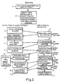
- the remote diagnosis software When the remote diagnosis software is run it will wait for a "hello" signal to be sent from the malfunctioning machine. Upon receipt of this signal the service agent software will:
- the master controller on the remote machine will decrypt this code and check for validity.
- the master controller will send a signal back to indicate the failure and break communications.
- Dedicated firmware may be provided to control who has permission to talk to the service board.
- Some service cards can be produced to accept ANY valid service agent access code. To allow this work we would have to ensure that the service agent access codes all follow a set format.
- One such format could be:
- the user of the host machine thus finds that he is unable to boot up his machine. Assuming the users machine has a service board fitted, the following sequence of events will put the problem right.
- a temperature sensor may be fitted or connected to the service card. Measurement of air temperature may help in diagnosing some faults.
- the power-up 'POST CODES' of the PC may be recorded and sent to the support company, giving indication of any power-up failure. This can identify at which stage the power-up sequence fails, and therefore can indicate the area of a fault within a users PC.
Claims (15)
- Appareil pour diagnostiquer et corriger des défauts dans un ordinateur central (2) ayant une première unité centrale de traitement (CPU) et des unités ancillaires, l'appareil comprenant deux parties: une première partie (12) prévue pour être couplée à l'ordinateur central, la première partie ayant une deuxième unité centrale de traitement pouvant être manoeuvrée pour mettre hors service et décaler la première unité centrale de traitement (CPU) et pour faire marcher et/ou interroger les unités ancillaires à sa place, une mémoire pour emmagasiner un numéro de série unique servant à identifier la première partie ou l'ordinateur central, et un code d'accès pour permettre une comparaison entre le code d'accès emmagasiné et un code engendré par la deuxième partie (18) pour refuser l'accès de la deuxième partie (18) à l'ordinateur central (2) si l'identité n'est pas constatée, la deuxième partie (18) étant disposée de façon à être couplée à la première partie (12) au moyen du même maillon de télécommunication (20) reliant l'usager de l'ordinateur central (2) à l'élément ancillaire de la deuxième partie (18) et pouvant être manoeuvrée de façon à diagnostiquer des défauts dans l'ordinateur (2) par l'intermédiaire de la première partie (12) et à effectuer au moins quelques mesures correctives par l'intermédiaire de la première partie (12).
- Appareil selon la revendication 1, dans lequel la première et la deuxième parties (12,18) sont associées chacune à un modem.
- Appareil selon la revendication 1 ou 2, dans lequel la première partie (12) comprend une carte de service (12) pouvant être fichée dans l'ordinateur central (2).
- Appareil selon la revendication 3, dans lequel la carte de service (12) comprend un module principal de commande (20) pour contrôler la première partie (12) et pour émettre des ordres et transmettre et recevoir des données par une interface de bus du système de l'ordinateur central (2).
- Appareil selon la revendication 3 ou 4, dans lequel la carte de service (12) comprend un module (24) mesurant la tension pour engendrer des tensions de référence et un moyen de comparaison pour les comparer avec des tensions de système sélectionnées dans l'ordinateur central (2).
- Appareil selon l'une quelconque des revendications précédentes, comprenant un moyen renifleur (26) de bus de système pour emmagasiner l'information du système provenant de l'ordinateur central (2).
- Appareil selon l'une quelconque des revendications précédentes dans lequel la première partie comprend un moyen pour effectuer un ou plusieurs ré-enclenchements du matériel de l'ordinateur central (2).
- Appareil selon l'une quelconque des revendications précédentes, dans lequel l'ordinateur central (2) est un ordinateur portatif (PC).
- Appareil selon l'une quelconque des revendications précédentes, dans lequel la première partie comprend une pile (12b).
- Appareil selon l'une quelconque des revendications précédentes, comprenant de surcroít un moyen de détecter la température.
- Méthode pour diagnostiquer et corriger des défauts dans un ordinateur central ayant une première unité de traitement (CPU) et des unités ancillaires, la méthode comprenant le fait de coupler une première partie qui comporte une deuxième unité centrale de traitement à l'ordinateur central, avec le résultat que la deuxième unité centrale de traitement décalera et mettra hors service la première unité centrale de traitement et fera fonctionner les unités ancillaires à sa place; couplant une deuxième partie à la première partie, au moyen du même maillon de télécommunication reliant l'usager de l'ordinateur central à l'élément de support pour la deuxième partie, emmagasinant un numéro de série unique qui pourra identifier la première partie ou l'ordinateur central et un code d'accès permettant une comparaison entre le code d'accès emmagasiné et un code engendré par la deuxième partie et refusant l'accès à la deuxième partie à l'ordinateur central si l'identité des codes n'est pas constatée, diagnostiquant des défauts dans l'ordinateur au niveau de la deuxième partie par l'intermédiaire de la deuxième unité de traitement de la première partie, et effectuant au moins quelques mesures correctives par la première partie.
- Méthode selon la revendication 11, dans laquelle la première partie est contrôlée de façon à recevoir des données par l'intermédiaire de l'interface de bus du système de l'ordinateur central.
- Méthode selon les revendications 11 ou 12, dans laquelle les tensions de référence sont engendrées et comparées avec des tensions du systèmes de l'ordinateur central sélectionnées.
- Méthode selon les revendications 11 à 13, dans laquelle l'information sur le système provenant de l'ordinateur central est emmagasinée.
- Méthode selon l'une quelconque des revendications 11 à 14, dans laquelle la première partie est disposée de façon à effectuer un ou plusieurs ré-enclenchements de matérial de l'ordinateur central en cas de nécessité.
Applications Claiming Priority (3)
| Application Number | Priority Date | Filing Date | Title |
|---|---|---|---|
| GB9611846 | 1996-06-06 | ||
| GB9611846A GB2313931B (en) | 1996-06-06 | 1996-06-06 | Methods and apparatus for diagnosing and correcting faults in computers |
| PCT/GB1997/001498 WO1997046940A1 (fr) | 1996-06-06 | 1997-06-03 | Procede et appareil pour diagnostiquer et corriger des defauts dans un ordinateur |
Publications (2)
| Publication Number | Publication Date |
|---|---|
| EP0978037A1 EP0978037A1 (fr) | 2000-02-09 |
| EP0978037B1 true EP0978037B1 (fr) | 2002-02-20 |
Family
ID=10794852
Family Applications (1)
| Application Number | Title | Priority Date | Filing Date |
|---|---|---|---|
| EP97924163A Expired - Lifetime EP0978037B1 (fr) | 1996-06-06 | 1997-06-03 | Procede et appareil pour diagnostiquer et corriger des defauts dans un ordinateur |
Country Status (6)
| Country | Link |
|---|---|
| US (1) | US6367035B1 (fr) |
| EP (1) | EP0978037B1 (fr) |
| AT (1) | ATE213552T1 (fr) |
| DE (1) | DE69710618T2 (fr) |
| GB (1) | GB2313931B (fr) |
| WO (1) | WO1997046940A1 (fr) |
Families Citing this family (23)
| Publication number | Priority date | Publication date | Assignee | Title |
|---|---|---|---|---|
| US6560726B1 (en) | 1999-08-19 | 2003-05-06 | Dell Usa, L.P. | Method and system for automated technical support for computers |
| US6606716B1 (en) | 1999-10-06 | 2003-08-12 | Dell Usa, L.P. | Method and system for automated technical support for computers |
| US6760708B1 (en) * | 1999-08-19 | 2004-07-06 | Dell Products L.P. | Method and system for migrating stored data to a build-to-order computing system |
| US6539499B1 (en) * | 1999-10-06 | 2003-03-25 | Dell Usa, L.P. | Graphical interface, method, and system for the provision of diagnostic and support services in a computer system |
| US6564220B1 (en) | 1999-10-06 | 2003-05-13 | Dell Usa, L.P. | System and method for monitoring support activity |
| US6563698B1 (en) | 1999-10-06 | 2003-05-13 | Dell Usa, L.P. | System and method for providing a computer system with a detachable component |
| US6598223B1 (en) | 1999-10-06 | 2003-07-22 | Dell Usa, L.P. | Method and system for installing and testing build-to-order components in a defined configuration computer system |
| US6601190B1 (en) * | 1999-10-28 | 2003-07-29 | Hewlett-Packard Development Company, L.P. | Automatic capture and reporting of computer configuration data |
| JP2001145131A (ja) * | 1999-11-15 | 2001-05-25 | Minolta Co Ltd | 電子機器の診断方法、電子機器の修理方法、検査プログラムの提供方法、診断装置、および、検査プログラム提供装置 |
| US6633876B1 (en) * | 2000-06-07 | 2003-10-14 | Sun Microsystems, Inc. | Analyzing post-mortem information on a remote computer system using a downloadable code module |
| US20020124211A1 (en) * | 2001-03-01 | 2002-09-05 | International Business Machines Corporation | PCI error determination using error signatures or vectors |
| US20020178387A1 (en) * | 2001-05-25 | 2002-11-28 | John Theron | System and method for monitoring and managing power use of networked information devices |
| US20030065864A1 (en) * | 2001-10-03 | 2003-04-03 | Dell Products L.P. | System and method supporting remote data processing system management |
| US6874060B2 (en) | 2001-12-07 | 2005-03-29 | Dell Products L.P. | Distributed computer system including a virtual disk subsystem and method for providing a virtual local drive |
| US7380167B2 (en) * | 2003-02-13 | 2008-05-27 | Dell Products L.P. | Method and system for verifying information handling system hardware component failure diagnosis |
| JP4049011B2 (ja) * | 2003-05-01 | 2008-02-20 | 株式会社島津製作所 | 分析装置の遠隔サポートシステム |
| US20050028034A1 (en) * | 2003-07-28 | 2005-02-03 | Alexander Gantman | Fault diagnosis, repair and upgrades using the acoustic channel |
| CN101681346A (zh) * | 2007-05-24 | 2010-03-24 | 费斯布克公司 | 用于访问互联网应用的个性化平台 |
| US9058230B1 (en) * | 2008-05-27 | 2015-06-16 | Symantec Operating Corporation | Online expert system guided application installation |
| US10146721B2 (en) | 2016-02-24 | 2018-12-04 | Mellanox Technologies, Ltd. | Remote host management over a network |
| US10474589B1 (en) | 2016-03-02 | 2019-11-12 | Janus Technologies, Inc. | Method and apparatus for side-band management of security for a server computer |
| US10382396B2 (en) | 2016-12-28 | 2019-08-13 | Mellanox Technologies, Ltd. | Utilizing management network for secured configuration and platform management |
| US10331598B2 (en) | 2017-02-22 | 2019-06-25 | Mellanox Technologies, Ltd. | Adding a network port to a network interface card |
Family Cites Families (6)
| Publication number | Priority date | Publication date | Assignee | Title |
|---|---|---|---|---|
| US4057847A (en) * | 1976-06-14 | 1977-11-08 | Sperry Rand Corporation | Remote controlled test interface unit |
| US4691316A (en) * | 1985-02-14 | 1987-09-01 | Support Technologies, Inc. | ROM emulator for diagnostic tester |
| US5274797A (en) * | 1986-05-30 | 1993-12-28 | Bull Hn Information Systems Inc. | Multiprocessor system with centralized initialization, testing and monitoring of the system and providing centralized timing |
| NZ220423A (en) * | 1986-05-30 | 1989-07-27 | Honeywell Bull | Multiprocessor system; shared resource status appears on bus |
| WO1992009954A1 (fr) | 1990-11-23 | 1992-06-11 | Tower Tech Srl | Dispositif de diagnostic servant a depister les defauts sur un ordinateur personnel |
| TW292365B (en) * | 1995-05-31 | 1996-12-01 | Hitachi Ltd | Computer management system |
-
1996
- 1996-06-06 GB GB9611846A patent/GB2313931B/en not_active Expired - Lifetime
-
1997
- 1997-06-03 AT AT97924163T patent/ATE213552T1/de not_active IP Right Cessation
- 1997-06-03 EP EP97924163A patent/EP0978037B1/fr not_active Expired - Lifetime
- 1997-06-03 DE DE69710618T patent/DE69710618T2/de not_active Expired - Lifetime
- 1997-06-03 WO PCT/GB1997/001498 patent/WO1997046940A1/fr active IP Right Grant
- 1997-06-03 US US09/194,964 patent/US6367035B1/en not_active Expired - Lifetime
Also Published As
| Publication number | Publication date |
|---|---|
| EP0978037A1 (fr) | 2000-02-09 |
| GB2313931A (en) | 1997-12-10 |
| WO1997046940A1 (fr) | 1997-12-11 |
| GB9611846D0 (en) | 1996-08-07 |
| ATE213552T1 (de) | 2002-03-15 |
| DE69710618D1 (de) | 2002-03-28 |
| DE69710618T2 (de) | 2002-10-17 |
| GB2313931B (en) | 2000-09-06 |
| US6367035B1 (en) | 2002-04-02 |
Similar Documents
| Publication | Publication Date | Title |
|---|---|---|
| EP0978037B1 (fr) | Procede et appareil pour diagnostiquer et corriger des defauts dans un ordinateur | |
| CA2074027C (fr) | Methode de configuration de systeme de traitement de donnees, systeme de traitement de donnees utilisant cette methode et unite d'expansion pour ce systeme | |
| US6880113B2 (en) | Conditional hardware scan dump data capture | |
| US6463550B1 (en) | Computer system implementing fault detection and isolation using unique identification codes stored in non-volatile memory | |
| US4775976A (en) | Method and apparatus for backing up data transmission system | |
| US6003081A (en) | Data processing system and method for generating a detailed repair request for a remote client computer system | |
| US4729124A (en) | Diagnostic system | |
| US6496790B1 (en) | Management of sensors in computer systems | |
| EP0684556A1 (fr) | Système de traitement d'information | |
| US5659801A (en) | Method and apparatus for replacing resident peripheral device control microcode by download via an application program | |
| US20020147941A1 (en) | Network based BIOS recovery method | |
| US6249812B1 (en) | Interactive system support using a system management asic | |
| US20080184025A1 (en) | Booting to a recovery/maintenance environment | |
| US5644700A (en) | Method for operating redundant master I/O controllers | |
| GB2318658A (en) | Remote diagnostics after boot error | |
| EP1588260A2 (fr) | Interfaces pour connexions a chaud et gestion des incidents | |
| CN113489597A (zh) | 用于网络装置的最佳启动路径的方法和系统 | |
| US7634649B2 (en) | Device initiated mode switching | |
| CN101853173A (zh) | 一种分布式系统的可编程逻辑器件的软件升级方法和设备 | |
| CN109032636A (zh) | 一种基于加密认证bmc更新uefi固件的方法 | |
| EP0671030A1 (fr) | Processeur et methode a securite intrinseque pour systeme de traitement de donnees | |
| US20040168164A1 (en) | Method and system for repair servicing of computers | |
| US7047565B2 (en) | Method and system for capturing in-service date information | |
| JP2002543521A (ja) | 自動的にモジュールをコンピュータシステムに再び組み込む方法および装置 | |
| Cisco | Troubleshooting |
Legal Events
| Date | Code | Title | Description |
|---|---|---|---|
| PUAI | Public reference made under article 153(3) epc to a published international application that has entered the european phase |
Free format text: ORIGINAL CODE: 0009012 |
|
| 17P | Request for examination filed |
Effective date: 19981207 |
|
| AK | Designated contracting states |
Kind code of ref document: A1 Designated state(s): AT BE CH DE DK ES FI FR GB GR IE IT LI LU MC NL PT SE |
|
| 17Q | First examination report despatched |
Effective date: 20000307 |
|
| GRAG | Despatch of communication of intention to grant |
Free format text: ORIGINAL CODE: EPIDOS AGRA |
|
| GRAG | Despatch of communication of intention to grant |
Free format text: ORIGINAL CODE: EPIDOS AGRA |
|
| GRAH | Despatch of communication of intention to grant a patent |
Free format text: ORIGINAL CODE: EPIDOS IGRA |
|
| GRAH | Despatch of communication of intention to grant a patent |
Free format text: ORIGINAL CODE: EPIDOS IGRA |
|
| REG | Reference to a national code |
Ref country code: GB Ref legal event code: IF02 |
|
| GRAA | (expected) grant |
Free format text: ORIGINAL CODE: 0009210 |
|
| AK | Designated contracting states |
Kind code of ref document: B1 Designated state(s): AT BE CH DE DK ES FI FR GB GR IE IT LI LU MC NL PT SE |
|
| PG25 | Lapsed in a contracting state [announced via postgrant information from national office to epo] |
Ref country code: NL Free format text: LAPSE BECAUSE OF FAILURE TO SUBMIT A TRANSLATION OF THE DESCRIPTION OR TO PAY THE FEE WITHIN THE PRESCRIBED TIME-LIMIT Effective date: 20020220 Ref country code: LI Free format text: LAPSE BECAUSE OF FAILURE TO SUBMIT A TRANSLATION OF THE DESCRIPTION OR TO PAY THE FEE WITHIN THE PRESCRIBED TIME-LIMIT Effective date: 20020220 Ref country code: IT Free format text: LAPSE BECAUSE OF FAILURE TO SUBMIT A TRANSLATION OF THE DESCRIPTION OR TO PAY THE FEE WITHIN THE PRESCRIBED TIME-LIMIT;WARNING: LAPSES OF ITALIAN PATENTS WITH EFFECTIVE DATE BEFORE 2007 MAY HAVE OCCURRED AT ANY TIME BEFORE 2007. THE CORRECT EFFECTIVE DATE MAY BE DIFFERENT FROM THE ONE RECORDED. Effective date: 20020220 Ref country code: GR Free format text: LAPSE BECAUSE OF FAILURE TO SUBMIT A TRANSLATION OF THE DESCRIPTION OR TO PAY THE FEE WITHIN THE PRESCRIBED TIME-LIMIT Effective date: 20020220 Ref country code: FI Free format text: LAPSE BECAUSE OF FAILURE TO SUBMIT A TRANSLATION OF THE DESCRIPTION OR TO PAY THE FEE WITHIN THE PRESCRIBED TIME-LIMIT Effective date: 20020220 Ref country code: CH Free format text: LAPSE BECAUSE OF FAILURE TO SUBMIT A TRANSLATION OF THE DESCRIPTION OR TO PAY THE FEE WITHIN THE PRESCRIBED TIME-LIMIT Effective date: 20020220 Ref country code: BE Free format text: LAPSE BECAUSE OF FAILURE TO SUBMIT A TRANSLATION OF THE DESCRIPTION OR TO PAY THE FEE WITHIN THE PRESCRIBED TIME-LIMIT Effective date: 20020220 Ref country code: AT Free format text: LAPSE BECAUSE OF FAILURE TO SUBMIT A TRANSLATION OF THE DESCRIPTION OR TO PAY THE FEE WITHIN THE PRESCRIBED TIME-LIMIT Effective date: 20020220 |
|
| REF | Corresponds to: |
Ref document number: 213552 Country of ref document: AT Date of ref document: 20020315 Kind code of ref document: T |
|
| REG | Reference to a national code |
Ref country code: CH Ref legal event code: EP |
|
| REF | Corresponds to: |
Ref document number: 69710618 Country of ref document: DE Date of ref document: 20020328 |
|
| PG25 | Lapsed in a contracting state [announced via postgrant information from national office to epo] |
Ref country code: SE Free format text: LAPSE BECAUSE OF FAILURE TO SUBMIT A TRANSLATION OF THE DESCRIPTION OR TO PAY THE FEE WITHIN THE PRESCRIBED TIME-LIMIT Effective date: 20020520 Ref country code: PT Free format text: LAPSE BECAUSE OF FAILURE TO SUBMIT A TRANSLATION OF THE DESCRIPTION OR TO PAY THE FEE WITHIN THE PRESCRIBED TIME-LIMIT Effective date: 20020520 Ref country code: DK Free format text: LAPSE BECAUSE OF FAILURE TO SUBMIT A TRANSLATION OF THE DESCRIPTION OR TO PAY THE FEE WITHIN THE PRESCRIBED TIME-LIMIT Effective date: 20020520 |
|
| PG25 | Lapsed in a contracting state [announced via postgrant information from national office to epo] |
Ref country code: MC Free format text: LAPSE BECAUSE OF NON-PAYMENT OF DUE FEES Effective date: 20020603 Ref country code: LU Free format text: LAPSE BECAUSE OF NON-PAYMENT OF DUE FEES Effective date: 20020603 Ref country code: IE Free format text: LAPSE BECAUSE OF NON-PAYMENT OF DUE FEES Effective date: 20020603 |
|
| NLV1 | Nl: lapsed or annulled due to failure to fulfill the requirements of art. 29p and 29m of the patents act | ||
| ET | Fr: translation filed | ||
| PG25 | Lapsed in a contracting state [announced via postgrant information from national office to epo] |
Ref country code: ES Free format text: LAPSE BECAUSE OF FAILURE TO SUBMIT A TRANSLATION OF THE DESCRIPTION OR TO PAY THE FEE WITHIN THE PRESCRIBED TIME-LIMIT Effective date: 20020829 |
|
| REG | Reference to a national code |
Ref country code: CH Ref legal event code: PL |
|
| PLBE | No opposition filed within time limit |
Free format text: ORIGINAL CODE: 0009261 |
|
| STAA | Information on the status of an ep patent application or granted ep patent |
Free format text: STATUS: NO OPPOSITION FILED WITHIN TIME LIMIT |
|
| 26N | No opposition filed |
Effective date: 20021121 |
|
| REG | Reference to a national code |
Ref country code: IE Ref legal event code: MM4A |
|
| REG | Reference to a national code |
Ref country code: GB Ref legal event code: 732E |
|
| REG | Reference to a national code |
Ref country code: FR Ref legal event code: TP |
|
| REG | Reference to a national code |
Ref country code: GB Ref legal event code: 732E |
|
| REG | Reference to a national code |
Ref country code: GB Ref legal event code: 732E |
|
| REG | Reference to a national code |
Ref country code: GB Ref legal event code: 732E |
|
| REG | Reference to a national code |
Ref country code: FR Ref legal event code: TP Ref country code: FR Ref legal event code: RM |
|
| REG | Reference to a national code |
Ref country code: GB Ref legal event code: 732E Free format text: REGISTERED BETWEEN 20090212 AND 20090218 |
|
| REG | Reference to a national code |
Ref country code: FR Ref legal event code: TP |
|
| REG | Reference to a national code |
Ref country code: FR Ref legal event code: PLFP Year of fee payment: 20 |
|
| PGFP | Annual fee paid to national office [announced via postgrant information from national office to epo] |
Ref country code: GB Payment date: 20160525 Year of fee payment: 20 |
|
| PGFP | Annual fee paid to national office [announced via postgrant information from national office to epo] |
Ref country code: FR Payment date: 20160531 Year of fee payment: 20 |
|
| PGFP | Annual fee paid to national office [announced via postgrant information from national office to epo] |
Ref country code: DE Payment date: 20160629 Year of fee payment: 20 |
|
| REG | Reference to a national code |
Ref country code: DE Ref legal event code: R071 Ref document number: 69710618 Country of ref document: DE |
|
| REG | Reference to a national code |
Ref country code: GB Ref legal event code: PE20 Expiry date: 20170602 |
|
| PG25 | Lapsed in a contracting state [announced via postgrant information from national office to epo] |
Ref country code: GB Free format text: LAPSE BECAUSE OF EXPIRATION OF PROTECTION Effective date: 20170602 |