EP0977931B1 - Überwachungssystem für mehrzonen-produktion - Google Patents
Überwachungssystem für mehrzonen-produktion Download PDFInfo
- Publication number
- EP0977931B1 EP0977931B1 EP98919833A EP98919833A EP0977931B1 EP 0977931 B1 EP0977931 B1 EP 0977931B1 EP 98919833 A EP98919833 A EP 98919833A EP 98919833 A EP98919833 A EP 98919833A EP 0977931 B1 EP0977931 B1 EP 0977931B1
- Authority
- EP
- European Patent Office
- Prior art keywords
- differential pressure
- fluid flow
- static pressure
- tool
- Prior art date
- Legal status (The legal status is an assumption and is not a legal conclusion. Google has not performed a legal analysis and makes no representation as to the accuracy of the status listed.)
- Expired - Lifetime
Links
- 238000004519 manufacturing process Methods 0.000 title claims description 74
- 238000012544 monitoring process Methods 0.000 title claims description 7
- 230000003068 static effect Effects 0.000 claims description 75
- 239000012530 fluid Substances 0.000 claims description 71
- 238000004891 communication Methods 0.000 claims description 26
- 230000008878 coupling Effects 0.000 claims description 20
- 238000010168 coupling process Methods 0.000 claims description 20
- 238000005859 coupling reaction Methods 0.000 claims description 20
- 239000004020 conductor Substances 0.000 claims description 19
- 230000001939 inductive effect Effects 0.000 claims description 14
- 238000000034 method Methods 0.000 claims description 13
- 238000005259 measurement Methods 0.000 claims description 10
- 238000009530 blood pressure measurement Methods 0.000 claims description 5
- 230000005540 biological transmission Effects 0.000 description 9
- 230000006870 function Effects 0.000 description 9
- 230000015654 memory Effects 0.000 description 6
- 230000015572 biosynthetic process Effects 0.000 description 4
- 238000005755 formation reaction Methods 0.000 description 4
- 238000011144 upstream manufacturing Methods 0.000 description 4
- 229930195733 hydrocarbon Natural products 0.000 description 3
- 150000002430 hydrocarbons Chemical class 0.000 description 3
- 239000000523 sample Substances 0.000 description 3
- 238000010276 construction Methods 0.000 description 2
- 230000000246 remedial effect Effects 0.000 description 2
- RZVAJINKPMORJF-UHFFFAOYSA-N Acetaminophen Chemical compound CC(=O)NC1=CC=C(O)C=C1 RZVAJINKPMORJF-UHFFFAOYSA-N 0.000 description 1
- 239000004568 cement Substances 0.000 description 1
- 238000013461 design Methods 0.000 description 1
- 238000003780 insertion Methods 0.000 description 1
- 230000037431 insertion Effects 0.000 description 1
- 238000009434 installation Methods 0.000 description 1
- 230000001105 regulatory effect Effects 0.000 description 1
- 230000004044 response Effects 0.000 description 1
Images


Classifications
-
- E—FIXED CONSTRUCTIONS
- E21—EARTH OR ROCK DRILLING; MINING
- E21B—EARTH OR ROCK DRILLING; OBTAINING OIL, GAS, WATER, SOLUBLE OR MELTABLE MATERIALS OR A SLURRY OF MINERALS FROM WELLS
- E21B47/00—Survey of boreholes or wells
- E21B47/10—Locating fluid leaks, intrusions or movements
-
- E—FIXED CONSTRUCTIONS
- E21—EARTH OR ROCK DRILLING; MINING
- E21B—EARTH OR ROCK DRILLING; OBTAINING OIL, GAS, WATER, SOLUBLE OR MELTABLE MATERIALS OR A SLURRY OF MINERALS FROM WELLS
- E21B23/00—Apparatus for displacing, setting, locking, releasing or removing tools, packers or the like in boreholes or wells
- E21B23/03—Apparatus for displacing, setting, locking, releasing or removing tools, packers or the like in boreholes or wells for setting the tools into, or removing the tools from, laterally offset landing nipples or pockets
-
- E—FIXED CONSTRUCTIONS
- E21—EARTH OR ROCK DRILLING; MINING
- E21B—EARTH OR ROCK DRILLING; OBTAINING OIL, GAS, WATER, SOLUBLE OR MELTABLE MATERIALS OR A SLURRY OF MINERALS FROM WELLS
- E21B47/00—Survey of boreholes or wells
- E21B47/06—Measuring temperature or pressure
Definitions
- the present invention relates to a side pocket mandrel system for use in a well containing more than one production zone, and also to a method for monitoring well production in a well containing more than one production zone.
- the well may contain multiple completions where more than one producing zone is traversed by a well bore and production can be obtained from more than one production zone into a common string of tubing.
- this invention has to do with a system for monitoring the quantity of production from independent production zones by independently measuring the differential pressure and the static pressure in a production zone on a real time basis while providing a full opening bore for production and remedial operations of lower zones.
- the system heretofore principally utilized uses multiple packers in a well casing where the packers separate production zones.
- a string of production tubing extends through the well packers and a side pocket mandrel is located in a section of the tubing string between a pair of production packers.
- the side pocket mandrel is utilized in the control of fluid flow which enters the tubing string through the bottom of the side pocket mandrel.
- One method of control is simply to block the passage so that fluid flow is stopped and fluid is produced from a selected side pocket and the fluid flow is measured at the earth's surface. In any event, it is not possible to ascertain what fluid flow occurs with any degree of preciseness and production is typically limited to one zone at a time.
- US-A-4624309 and US-A-4825946 disclose apparatus including a single side pocket mandrel for inclusion in a well tubing string and for removably receiving an instrument for monitoring pressure.
- the above referenced patents make no reference to monitoring pressure differential from fluid flow through a side pocket bore, and therefore are relevant to the technological background only of the present invention.
- the present invention provides a side pocket mandrel system for use in a well containing more than one production zone where the production zones are isolated from one another and where the production zones are produced into a common production tubing, the side pocket mandrel system comprising:
- the present invention also provides a method for monitoring well production in a well containing more than one production zone where the production zones are isolated from one another and where the production zones are produced into a common production tubing, said method comprising:
- a side pocket mandrel is provided with a full opening bore, i.e. a bore which does not restrict the passage of well tools.
- the side pocket mandrel has an lengthwise extending side by side elongated pockets (1) for receiving a static pressure measuring instrument or tool (static pressure pocket); (2) for providing an elongated pressure differential flow passageway (flow passageway pocket); and (3) for receiving a differential pressure measuring tool (differential pressure pocket).
- the static pressure measuring tool and the differential pressure measuring tool or instrument are commonly connected by a data coupling means to a single electrical conductor line which is strapped to the string of tubing and extends to the earth's surface for transmission of control signals and data between the earth's surface and the various side pocket tools.
- the differential flow passageway is connected for fluid communication with the static pressure pocket and the differential pressure pocket in the side pocket mandrel. Fluid flow in the production zone is channelled through the flow passageway to the full opening bore and the fluid is communicated to the static pressure measuring tool and to the differential pressure tool.
- the flow passageway is constructed and arranged to develop a differential pressure which is measured by the differential pressure measuring tool and which can be stored in a memory of the tool.
- the static pressure of the production fluid in the production zone is measured by the static pressure measuring tool. Both the differential pressure measurements and the static pressure measurements can be recorded in a memory as a function of real time.
- a real time reference can also be generated in the well tools and initiated when the tools are installed for use with a memory.
- both the static pressure tool and the differential pressure tool can be independently retrieved at any time and the memories can then be read out independently at the earth's surface should the conductor line fail to function for one reason or another.
- the static pressure and differential pressure of fluid flow from each production zone is independently measured at the time of production and sequentially and repetitively read out at the earth's surface. From the pressure measurements and flow equations, the production flow is determined.
- a full bore opening is also provided so that any remedial operations or the like can be conducted on lower zones without requiring removal of any other devices in full opening bore.
- a well bore 15 is illustrated as traversing earth formations which include production zones 16,17, and 18. While the illustration is relative to earth formations, it is the same principal with respect to underwater completions where as platform or the like serves as an earth surface and underwater production zones are connected by lateral pipes to independent production zones along a well pipe or casing.
- Perforations 16a, 17a and 18a typically place the hydrocarbons in the earth formations in fluid communication with the bores 22(A-C) of the liner sections 21(A-C).
- a string of tubing 25 extends from a well head 26 and extends through production packers 26(A-D) which isolate the production zones between adjacent packers in the liners.
- each side pocket mandrel 27,28, and 29 Disposed in each of the production zones between spaced apart packers and connected in the string of tubing is a side pocket mandrel 27,28, and 29 where each side pocket mandrel has a full opening bore which provides an uninterrupted continuation of the bore of the tubing string. Fluid flow from the respective production zones enters the liner sections and passes through the lengthwise extending side pockets of the side pocket mandrels.
- the side pocket mandrels have flow passageways communicating the annulus in the casing with the tubing string.
- a controller-read out means 29 which is connected by a single electrical conductor 24 to each of the downhole side pocket mandrels.
- the controller-read out means 29 provides a polling signal to each of the side pocket mandrels through data transmission techniques and reads out independent static pressure and differential pressure of fluid flow through a side pocket mandrel.
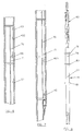
- an overall construction configuration of the side pocket mandrel is as follows: the side pocket mandrel 30 as illustrated is interconnected between adjacent tubing pup joints or sections 31A and 31B of a string of tubing or production tubing so as to form a part of the string of tubing.
- the side pocket mandrel 30 is generally an elongated cylindrically shaped member formed by four sections or parts comprising, from top to bottom, respectively, an upper takeout housing part 36, a body pipe part 38, a side pocket housing part 40, and a lower housing part 42.
- Each mandrel part 36, 38, 40 respectively have aligned full opening bores 36A, 38A, and 40A, which are equal or larger than the bore of the production tubing 25.
- the full opening bores extend through the length of mandrel 30 so that the mandrel 30 has an effective full opening bore:
- the effective full opening bore permits wireline side pocket well tools and other small diameter tools to pass through mandrel 30 to locations below and in the mandrel 30.
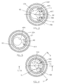
- a side pocket bore 40B as illustrated in Fig. 2 is sized to receive a static pressure tool.
- a conduit or pipe 41A Extending lengthwise through the housing part 40 and offset from the side pocket bores 40B,40C and 40D and the full opening bore 40A is a conduit or pipe 41A which is sized to pass an electrical conductor therethrough. As shown in Fig. 3 and 4, a second, blank conduit or pipe 41B located on the other side of pocket bore 40C can be provided for a guide pipe, if desired.
- fluid bypass ports which are openings in a wall surface which place the bores 40A and 40B in fluid communication so that a static pressure well tool can be received in the static pressure pocket 40B.
- an inductive coupling probe member 45 is disposed in the lower end of the pocket 40B.
- the coupling member 45 is sealingly attached to the lower end of the pocket 40B.
- the coupling member 45 cooperates with a socket coupling member on a well tool for the transmission of data between a well tool and an electrical conductor 24 which passes through in the conduit 41A and out the upper end of the side pocket mandrel.
- the electrical conductor 24 attached to the inductive coupling member 45 can be connected through a "Y" coupling so that the conductor 24 also extends downwardly to another well tool.
- the upper body part 38 is a tubular member with an internal bore and an enlarged lower bore at its lower end.
- the lower end of the part 38 is coupled to the housing part 40.
- the bore 38B receives the upper cut away portion of the housing part 40.
- the take out housing part 36 has a central portion with an enlarged bore which receives a tubular deflector 36B.
- the tubular deflector 36B has guide means 36C which guide a kickover tool for orientation relative to an offset pocket bore.
- the upper end of the part 36 has an offset internally threaded bore for threadedly receiving the tubing sub 31A.
- the tubing sub 31A engages the deflector 36B which is locked in rotative position by a locking key.
- the tubular pipe member 41A extends longitudinally between the bore in the part 40 and a bore 41B in the part 36.
- the pipe member 41A protects and encloses the electrical conductor 24 with respect to the open space.
- an open annulus 65 between the casing section 22A and the exterior of a typical side pocket mandrel 15 contains the flow of hydrocarbons from a production zone.
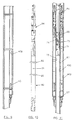
- a central flow passageway pocket 40C is in communication with the open annulus 65 by virtue of a lower passageway 67 which opens to the bottom end of the side pocket mandrel (see Fig. 6 and 11).
- a Venturi bore 68 which opens to an upper passageway 69. Fluid flow from the annulus (and the production zone) is thus directed through the flow passageway pocket 40C to the full open bore of the tubing string.
- a first passage means comprising transverse communication passageways 70 and 71 which are located above and below the Venturi bore and are in fluid communication with a differential pressure measuring tool 74 (see Fig. 8) which develops communication signal data as a function of the differential pressure of the fluid flow in the flow passageway pocket 40C.
- a design is illustrated wherein the flow passageway pocket 40C receives a retrievable Venturi assembly 75 which can be removed from the side pocket 40C with a removal and insertion tool 75 (Fig. 12) which will be discussed hereafter.
- the upstream and downstream pressure differential communication passageways 71,70 are coupled for fluid communication to the differential pressure pocket bore 40D which contain a differential pressure measuring tool 74.
- the differential pressure pocket 40D is constructed generally as illustrated in Fig. 2 with an inductive coupling probe member 45 at its lower end and is constructed and arranged to releasably receive a differential pressure measuring tool 74.
- the tool 74 is sized and adapted to be retreivably located within the differential pressure pocket 40D.
- the differential pressure tool 74 has spaced apart ports 77 and 78 which are located between spaced apart seals 79, 80, 81 so that when the tool is in the pocket 40D, the port 77 of the tool 74 is communication with the communication passageway 71 and the port 78 is in communication with the passageway 70.
- pressure of the fluid abaove and below the Venturi bore are supplied to the tool 74.
- the tool 74 In response to sensing of the pressures, the tool develops a data transmission code representative of the differential pressure sensed in the flow passageway pocket 40C.
- the tool 74 includes a retrieving and latching head assembly 82 which functions with a placement tool (see Fig. 12) to be disposed or removed from the side pocket 40D.
- a placement tool see Fig. 12
- the tool 74 When the tool 74 is in the pocket 40D it is latched in position and the data is developed in an electronic means within the tool and available for transmission to the electrical conductor 24 via the coupling member 45.
- the tool 74 can also include a memory section with a clock means where the data can be stored as a function of real time in the tool and read out independently after being retrieved.
- the static pressure pocket 40B is constructed generally as illustrated in Fig. 2 with an inductive coupling probe member 45 at it's lower end and a static pressure measuring tool 90 is sized and adapted to be retreivably located within the static pressure pocket 40B.
- the static pressure tool 90 has pressure sensing ports 91 which are located between spaced apart seals 92 and 93 so that when the tool 90 is in the pocket 40B, the ports 91 of the tool are in communication with a second passage means comprising a communication passageway 94 to the flow passageway pocket (see Fig.4).
- static pressure is supplied to the tool 90 which develops a data transmission code representative of the static pressure sensed in the flow passageway 40C.
- the tool 90 includes a retrieving and latching head assembly 94 which functions with a placement tool (see Fig. 12) to be disposed or removed from the side pocket 40B.
- a placement tool see Fig. 12
- the tool 90 When the tool 90 is in the static pressure pocket it is latched in position and the data is developed in an electronic means within the static pressure tool and available for transmission to the electrical conductor 24 via the coupling member 45.
- the tool can also include a memory section with a clock means where the data can be stored as a function of real time in the tool and read out independently after being retrieved.
- a placement and retrieving tool 75 is illustrated and includes an elongated housing 99 attached to a release housing 100.
- An articulated linkage mechanism 101 is connected to a pulling or retrieving tool 102 for disposition or removal of a tool or member from a side pocket bore.
- the production packers 26(A-D), the string of tubing 25, the side pocket mandrels 27,28,29, as desired and the electrical conductor 24 are installed so that there is an electrical communication conductor connection to all of the side pocket mandrels and to the controller-read out means 29 at the earth's surface or operating platform.
- each of the aformentioned side pocket mandrels there are three side pocket bores which are offset from a full opening bore where the full opening bore is in alignment with the full opening of the tubing string.
- the three side pocket bores respectively define: a fluid flow pocket 40C; a static pressure pocket 40B; and a differential pressure pocket 40D.
- the fluid flow pocket 40C opens to the bottom of a side pocket mandrel and is in direct communication with the full opening bore of a side pocket mandrel so that production flow is through the fluid flow passageway pocket to the string of tubing.
- a Venturi means 68 Disposed within the fluid flow pocket 40C is a Venturi means 68 which develops a differential pressure of the fluid between upstream and downstream fluid flow.
- the fluid flow pocket 40C has a transverse passageway 94 coupling the static pressure in the fluid flow pocket 40C to the static pressure pocket 40B.
- a static pressure measuring tool 90 Disposed in the static pressure pocket 40B is a static pressure measuring tool 90 which is releasably latched in the static pressure bore and has an inductive coupling means cooperating with an inductive coupler 45 in the static pressure pocket 40B.
- the static pressure measuring tool 90 develops a data signal as a function of static pressure.
- the differential pressure measuring pocket 40D has separate passageways 70,71 to the upstream and downstream pressure developed by the Venturi means 68.
- a differential pressure measuring tool 74 is retreivably disposed within the differential pressure pocket 40D with seal means and senses the upstream and downstream pressure and develops a data signal as a function of the differential pressure in the fluid flow pocket 40C.
- the differential pressure measuring tool 74 has and inductive coupling means cooperating with an inductive coupler 45 in the differential pressure pocket 40D.
- the various tools can be installed and removed as desired. While not illustrated, as it is conventional, the various side pockets can be mechanically coded with respect to the installation and retrieving tool so that the section of tool can be more precisely controlled.
- the controller read out means 29 sends a data polling signal to the respective static pressure tool and the differential pressure tool in each side pocket and sequentially and repetitively reads out the current differential pressure and static pressure from each side pocket as the transmission occurs at the platform or earth's surface.
- the fluid flow can be calculated from standard flow equations.
- each the production zones can be simultaneously produced into the string of tubing and the production from each production zone is determinable. Hence, there is no need to shut down one or more production zones to determine the production flow from any given zone.
- the full opening bore permits operations at any time at any location without requiring removal of any obstructions in the string of tubing.
- the differential pressure measuring tool, the static measuring tool, the controller-read out means, running and kick over tools are available from Panex Corporation at Sugar Land, Texas and/or are also disclosed in various prior patent applications and patents.
Landscapes
- Geology (AREA)
- Life Sciences & Earth Sciences (AREA)
- Engineering & Computer Science (AREA)
- Mining & Mineral Resources (AREA)
- Physics & Mathematics (AREA)
- Environmental & Geological Engineering (AREA)
- Fluid Mechanics (AREA)
- General Life Sciences & Earth Sciences (AREA)
- Geochemistry & Mineralogy (AREA)
- Geophysics (AREA)
- Measuring Fluid Pressure (AREA)
- Measuring Volume Flow (AREA)
- Coating Apparatus (AREA)
Claims (12)
- Seitentaschendomsystem zur Verwendung in einem Bohrloch (15), das mehr als einen Produktionsbereich (16, 17, 18) enthält, wobei die Produktionsbereiche voneinander isoliert sind und wobei die Produktionsbereiche zu einer gemeinsamen Produktionsröhre (25) gebildet sind, wobei das Seitentaschendornsystem Folgendes umfasst:wobei mindestens eine der Seitentaschenbohrungen, die hierin Statikdrucktasche (40B) genannt wird, zur Aufnahme eines Messinstruments für statischen Druck (90) konstruiert und angeordnet ist;mindestens einen länglichen Seitentaschendom (27, 28, 29, 30) mit einem Körperelement, das für den Anschluss in eine Reihe von Röhren für mindestens einen der Produktionsbereiche konstruiert und angeordnet ist, wobei der Seitentaschendom eine Vollöffnungsbohrung (36A, 38A, 40A) und nebeneinander angeordnete, lateral versetzte längliche Seitentaschenbohrungen (40B, 40C, 40D) aufweist;
dadurch gekennzeichnet, dass mindestens eine der Seitentaschenbohrungen, die hierin Fluidströmungstasche (40C) genannt wird, zur Bereitstellung eines Fluidströmungsdurchgangs und eines Mittels (68) in der Fluidströmungstasche zur Entwicklung eines Differenzialdrucks von der Fluidströmung durch die Fluidströmungstasche konstruiert und angeordnet ist;
mindestens eine der Seitentaschenbohrungen, die hierin Differenzialdrucktasche (40D) genannt wird, zur Aufnahme eines Differenzialdruckmessinstrument (74) konstruiert und angeordnet ist;
wobei ein erstes Durchgangsmittel (70, 71) die Fluidströmungstasche mit der Differenzialdrucktasche verbindet, um die Messung des Differenzialdrucks zu ermöglichen; und
ein zweites Durchgangsmittel (94) die Fluidströmungstasche mit der Statikdrucktasche verbindet, um die Messung des statischen Drucks zu ermöglichen. - Vorrichtung nach Anspruch 1, wobei mindestens entweder die Statikdrucktasche (40B) oder die Differenzialdrucktasche (40D) ein induktives Kopplungsmittel (45) umfasst, das an einen elektrischen Leiter (24) angeschlossen ist, der sich zur Kommunikation zwischen der Oberfläche und dem in einer der Taschen befindlichen Instrument (90, 74) zu einer Stelle an der Oberfläche erstrecken kann.
- Vorrichtung nach Anspruch 1, wobei sowohl die Statikdrucktasche (40B) als auch die Differenzialdrucktasche (40D) ein induktives Kopplungsmittel (45) umfasst, das an einen elektrischem Leiter (24) angeschossen ist, der sich zur Kommunikation zwischen der Oberfläche und dem in einer der Taschen befindlichen Instrument (90, 74) zu einer Stelle an der Oberfläche erstrecken kann.
- Vorrichtung nach Anspruch 1, wobei der Seitentaschendorn (27, 28, 29, 30) zur Anordnung in mindestens zwei Produktionsbereichen (16, 17, 18) ausgelegt ist, wobei mindestens entweder die Statikdrucktasche (40B) oder die Differenzialdrucktasche (40D) für jedes Instrument (90, 74) ein induktives Kopplungsmittel (45) umfasst, das an einen gemeinsamen elektrischen Leiter (24) angeschlossen ist, der sich zur Kommunikation zwischen der Oberfläche und dem in einer der Taschen befindlichen Instrument (90, 74) zu einer Stelle an der Oberfläche erstrecken kann.
- Vorrichtung nach Anspruch 1, wobei das Mittel (68) zur Entwicklung eines Druckdifferenzials ein Venturi-Bohrungselement umfasst und das erste Durchgangsmittel (70, 71) an Stellen oberhalb und unterhalb der Venturi-Bohrung mit der Fluidströmungstasche (40C) verbunden ist.
- Verfahren zur Überwachung einer Bohrlochproduktion in einem Bohrloch (15), das mehr als einen Produktionsbereich (16, 17, 18) umfasst, wobei die Produktionsbereiche voneinander isoliert sind und zu einer gemeinsamen Produktionsröhre (25) gebildet sind, wobei das Verfahren Folgendes umfasst:Anordnen eines Seitentaschendoms (27, 28, 29, 30) auf einer Reihe von Röhren in einem Produktionsbereich, wobei der Seitentaschendom ein längliches Körperelement (36, 38, 40, 42) und eine Vollöffnungsbohrung (36A, 38A, 40A) sowie nebeneinander angeordnete, lateral versetzte längliche Seitentaschenbohrungen (40B, 40C, 40D) aufweist und wobei mindestens eine der Seitentaschenbohrungen, die hierin Statikdrucktasche (40B) genannt wird, zur Aufnahme eines Messinstruments (90) für statischen Druck konstruiert und angeordnet ist; und wobei mindestens eine der Seitentaschenbohrungen, die hierin Fluidströmungstasche (40C) genannt wird, zur Bereitstellung eines Fluidströmungsdurchgangs konstruiert und angeordnet ist, dadurch gekennzeichnet, dass ein Mittel (68) in der Fluidströmungstasche angeordnet ist, um einen Differenzialdruck von der Fluidströmung durch die Fluidströmungstasche zu entwickeln, und mindestens eine der Seitentaschenbohrungen, die hierin Differenzialdrucktasche (40D) genannt wird, zur Aufnahme eines Differenzialdruckmessinstrument (74) konstruiert und angeordnet ist; wobei ein erstes Durchgangsmittel (70, 71) die Fluidströmungstasche mit der Differenzialdrucktasche verbindet, um die Messung des Differenzialdrucks zu ermöglichen, und ein zweites Durchgangsmittel (94) die Fluidströmungstasche mit der Statikdrucktasche verbindet, um die Messung des statischen Drucks zu ermöglichen;Anordnen des Messinstruments für statischen Druck in der Statikdrucktasche und eines Differenzialdruck-Messinstruments in der Differenzialdrucktasche.
- Verfahren nach Anspruch 6, das des Weiteren folgenden Schritt umfasst:Einrichten einer Kommunikationsverbindung zwischen mindestens einem der Instrumente (90, 74) und einer Oberflächenstelle zur Kommunikation zwischen dem Instrument und der Oberflächenstelle.
- Verfahren nach Anspruch 6, wobei mindestens entweder die Statikdrucktasche (40B) oder die Differenzialdrucktasche (40D) ein induktives Kopplungsmittel(45) umfasst, das an einen elektrischen Leiter (24) angeschlossen ist, der sich zur Kommunikation zwischen der Oberfläche und dem in einer der Taschen befindlichen Instrument (90, 74) zu einer Stelle an der Oberfläche erstreckt, wobei das Verfahren den weiteren Schritt des Anordnens des einen Instruments in dem Seitentaschendorn umfasst, so dass es wiedererlangt werden kann.
- Verfahren nach Anspruch 8, wobei sowohl die Statikdrucktasche (40B) als auch die Differenzialdrucktasche (40D) ein induktives Kopplungsmittel(45) umfasst, das an einen elektrischem Leiter (24) angeschossen ist, der sich zur Kommunikation zwischen der Oberfläche und dem in einer der Taschen befindlichen Instrument zu einer Stelle an der Oberfläche erstreckt, wobei das Verfahren den weiteren Schritt des wiedererlangbaren Anordnens eines Messinstruments für statischen Druck (90) in der Statikdrucktasche und des Anordnens eines Differenzialdruck-Messinstrument (74) in der Differenzialdrucktasche umfasst.
- Verfahren nach Anspruch 6, das des Weiteren den Schritt des Anordnens des Seitentaschendoms (27, 28, 29, 30) in mindestens zwei Produktionsbereichen (16, 17, 18) in einer Bohrlochbohrung (15) umfasst, wobei die Seitentaschendome jeweils das längliche Körperelement (36, 38, 40, 42) und die Vollöffnungsbohrung (36A, 38A, 40A) sowie nebeneinander angeordnete, lateral versetzte längliche Seitentaschenbohrungen (40B, 40C, 40D) aufweisen und wobei in jedem Seitentaschendom mindestens eine der Seitentaschenbohrungen, die hierin Statikdrucktasche (40B) genannt wird, zur Aufnahme eines Messinstruments (90) für statischen Druck konstruiert und angeordnet ist und wobei mindestens eine der Seitentaschenbohrungen, die hierin Fluidströmungstasche (40C) genannt wird, zur Bereitstellung eines Fluidströmungsdurchgangs konstruiert und angeordnet ist und das Mittel (68) in der Fluidströmungstasche zur Entwicklung eines Differenzialdrucks von der Fluidströmung durch die Fluidströmungstasche angeordnet ist, und wobei mindestens eine der Seitentaschenbohrungen, die hierin Differenzialdrucktasche (40D) genannt wird, zur Aufnahme des Differenzialdruck-Messinstruments (74) konstruiert und angeordnet ist, und wobei das erste Durchgangsmittel (70, 71) die Fluidströmungstasche mit der Differenzialdrucktasche verbindet, um die Messung des Differenzialdrucks zu ermöglichen, und ein zweites Durchgangsmittel (94) die Fluidströmungstasche mit der Statikdrucktasche verbindet, um die Messung des statischen Drucks zu ermöglichen;
wobei das Messinstrument für statischen Druck (90) in jeder der Statikdrucktaschen und das Differenzialdruck-Messinstrument (74) in den Differenzialdrucktaschen angeordnet ist. - Verfahren nach Anspruch 10, das des Weiteren folgenden Schritt umfasst:Einrichten einer Kommunikationsverbindung zwischen mindestens einem der Instrumente (90, 74) in jedem der Seitentaschendome und einer Oberflächenstelle zur Kommunikation zwischen dem Instrument und der Oberflächenstelle.
- Verfahren nach Anspruch 11, wobei mindestens entweder die Statikdrucktasche (40B) oder die Differenzialdrucktasche (40D) ein induktives Kopplungsmittel (45) umfasst, das an einen gemeinsamen elektrischen Leiter (24) angeschlossen ist, der sich zur Kommunikation zwischen der Oberfläche und dem in einer der Taschen befindlichen Instrument (90, 74) zu einer Stelle an der Oberfläche erstreckt, wobei das Verfahren den weiteren Schritt des wiedererlangbaren Anordnens mindestens eines der Instrumente in einem Seitentaschendom umfasst.
Applications Claiming Priority (3)
| Application Number | Priority Date | Filing Date | Title |
|---|---|---|---|
| US4453897P | 1997-04-23 | 1997-04-23 | |
| US44538P | 1997-04-23 | ||
| PCT/US1998/008066 WO1998048145A1 (en) | 1997-04-23 | 1998-04-22 | Multizone production monitoring system |
Publications (3)
| Publication Number | Publication Date |
|---|---|
| EP0977931A1 EP0977931A1 (de) | 2000-02-09 |
| EP0977931A4 EP0977931A4 (de) | 2000-06-28 |
| EP0977931B1 true EP0977931B1 (de) | 2004-08-18 |
Family
ID=21932943
Family Applications (1)
| Application Number | Title | Priority Date | Filing Date |
|---|---|---|---|
| EP98919833A Expired - Lifetime EP0977931B1 (de) | 1997-04-23 | 1998-04-22 | Überwachungssystem für mehrzonen-produktion |
Country Status (4)
| Country | Link |
|---|---|
| EP (1) | EP0977931B1 (de) |
| CA (1) | CA2286758A1 (de) |
| NO (1) | NO319986B1 (de) |
| WO (1) | WO1998048145A1 (de) |
Families Citing this family (4)
| Publication number | Priority date | Publication date | Assignee | Title |
|---|---|---|---|---|
| US6082455A (en) * | 1998-07-08 | 2000-07-04 | Camco International Inc. | Combination side pocket mandrel flow measurement and control assembly |
| WO2000070187A1 (en) * | 1999-05-13 | 2000-11-23 | Baker Hughes Incorporated | Flow monitoring and control in multi-lateral wellbores |
| BR112013023019A2 (pt) * | 2011-03-09 | 2016-12-13 | Prad Res & Dev Ltd | método para caracterizar uma formação subterrânea utilizando uma resposta de pressão de fluido durante operações de perfuração de poços, e método para calcular vazão de fluido fluindo de um poço, baseado em uma resposta da pressão de fluido durante operações de perfuração de poço |
| DE102019124386A1 (de) | 2019-09-11 | 2021-03-11 | Audi Ag | Verfahren zum Betreiben einer Virtual-Reality-Brille in einem Fahrzeug sowie Virtual-Reality-System mit einer Virtual-Reality-Brille und einem Fahrzeug |
Family Cites Families (2)
| Publication number | Priority date | Publication date | Assignee | Title |
|---|---|---|---|---|
| US4825946A (en) * | 1984-09-24 | 1989-05-02 | Otis Engineering Corporation | Apparatus for monitoring a parameter in a well |
| US4624309A (en) * | 1984-09-24 | 1986-11-25 | Otis Engineering Corporation | Apparatus for monitoring a parameter in a well |
-
1998
- 1998-04-22 EP EP98919833A patent/EP0977931B1/de not_active Expired - Lifetime
- 1998-04-22 WO PCT/US1998/008066 patent/WO1998048145A1/en not_active Ceased
- 1998-04-22 CA CA002286758A patent/CA2286758A1/en not_active Abandoned
-
1999
- 1999-10-25 NO NO19995215A patent/NO319986B1/no not_active IP Right Cessation
Also Published As
| Publication number | Publication date |
|---|---|
| EP0977931A4 (de) | 2000-06-28 |
| EP0977931A1 (de) | 2000-02-09 |
| CA2286758A1 (en) | 1998-10-29 |
| NO995215L (no) | 1999-11-18 |
| WO1998048145A1 (en) | 1998-10-29 |
| NO319986B1 (no) | 2005-10-10 |
| NO995215D0 (no) | 1999-10-25 |
Similar Documents
| Publication | Publication Date | Title |
|---|---|---|
| US6422312B1 (en) | Multizone production monitoring system | |
| US4790378A (en) | Well testing apparatus | |
| CA2610525C (en) | Multi-zone formation evaluation systems and methods | |
| US6983796B2 (en) | Method of providing hydraulic/fiber conduits adjacent bottom hole assemblies for multi-step completions | |
| US5934371A (en) | Pressure test method for permanent downhole wells and apparatus therefore | |
| CA2426968C (en) | Method and apparatus for subsurface fluid sampling | |
| US9441477B2 (en) | Multiple distributed pressure measurements | |
| EP0145537B1 (de) | Prüfstrang zur Untersuchung eines Bohrloches mit verschiedenen Druckmessungslöchern | |
| US7475732B2 (en) | Instrumentation for a downhole deployment valve | |
| CA2270236C (en) | Communication conduit in a well tool | |
| US6330913B1 (en) | Method and apparatus for testing a well | |
| US7159653B2 (en) | Spacer sub | |
| US20070221407A1 (en) | Permanent downhole deployment of optical sensors | |
| US7261161B2 (en) | Well testing system | |
| US6959763B2 (en) | Method and apparatus for integrated horizontal selective testing of wells | |
| US6644110B1 (en) | Measurements of properties and transmission of measurements in subterranean wells | |
| US20050121190A1 (en) | Segregated deployment of downhole valves for monitoring and control of multilateral wells | |
| EP0774565A2 (de) | Imbohrloch-Einrichtung zur Gewinnung von Bohrloch-Informationen | |
| US6230812B1 (en) | Side pocket mandrel | |
| EP0977931A1 (de) | Überwachungssystem für mehrzonen-produktion | |
| GB2297571A (en) | Well logging and control system | |
| GB2261519A (en) | Hydro-carbon flow rate monitor | |
| AU765362B2 (en) | Flow monitoring and control in multi-lateral wellbores |
Legal Events
| Date | Code | Title | Description |
|---|---|---|---|
| PUAI | Public reference made under article 153(3) epc to a published international application that has entered the european phase |
Free format text: ORIGINAL CODE: 0009012 |
|
| 17P | Request for examination filed |
Effective date: 19991117 |
|
| AK | Designated contracting states |
Kind code of ref document: A1 Designated state(s): FR GB |
|
| A4 | Supplementary search report drawn up and despatched |
Effective date: 20000516 |
|
| AK | Designated contracting states |
Kind code of ref document: A4 Designated state(s): FR GB |
|
| RIC1 | Information provided on ipc code assigned before grant |
Free format text: 7E 21B 47/06 A, 7E 21B 23/03 B, 7E 21B 47/10 B |
|
| 17Q | First examination report despatched |
Effective date: 20020729 |
|
| GRAH | Despatch of communication of intention to grant a patent |
Free format text: ORIGINAL CODE: EPIDOS IGRA |
|
| GRAS | Grant fee paid |
Free format text: ORIGINAL CODE: EPIDOSNIGR3 |
|
| GRAA | (expected) grant |
Free format text: ORIGINAL CODE: 0009210 |
|
| AK | Designated contracting states |
Kind code of ref document: B1 Designated state(s): FR GB |
|
| PG25 | Lapsed in a contracting state [announced via postgrant information from national office to epo] |
Ref country code: FR Free format text: LAPSE BECAUSE OF FAILURE TO SUBMIT A TRANSLATION OF THE DESCRIPTION OR TO PAY THE FEE WITHIN THE PRESCRIBED TIME-LIMIT Effective date: 20040818 |
|
| REG | Reference to a national code |
Ref country code: GB Ref legal event code: FG4D |
|
| PGFP | Annual fee paid to national office [announced via postgrant information from national office to epo] |
Ref country code: FR Payment date: 20050408 Year of fee payment: 8 |
|
| PLBE | No opposition filed within time limit |
Free format text: ORIGINAL CODE: 0009261 |
|
| STAA | Information on the status of an ep patent application or granted ep patent |
Free format text: STATUS: NO OPPOSITION FILED WITHIN TIME LIMIT |
|
| 26N | No opposition filed |
Effective date: 20050519 |
|
| EN | Fr: translation not filed | ||
| PGFP | Annual fee paid to national office [announced via postgrant information from national office to epo] |
Ref country code: GB Payment date: 20160420 Year of fee payment: 19 |
|
| GBPC | Gb: european patent ceased through non-payment of renewal fee |
Effective date: 20170422 |
|
| PG25 | Lapsed in a contracting state [announced via postgrant information from national office to epo] |
Ref country code: GB Free format text: LAPSE BECAUSE OF NON-PAYMENT OF DUE FEES Effective date: 20170422 |