EP0977526B1 - Multi-variable height fusion device - Google Patents
Multi-variable height fusion device Download PDFInfo
- Publication number
- EP0977526B1 EP0977526B1 EP98920096A EP98920096A EP0977526B1 EP 0977526 B1 EP0977526 B1 EP 0977526B1 EP 98920096 A EP98920096 A EP 98920096A EP 98920096 A EP98920096 A EP 98920096A EP 0977526 B1 EP0977526 B1 EP 0977526B1
- Authority
- EP
- European Patent Office
- Prior art keywords
- engaging plates
- strut
- spinal implant
- height
- engaging
- Prior art date
- Legal status (The legal status is an assumption and is not a legal conclusion. Google has not performed a legal analysis and makes no representation as to the accuracy of the status listed.)
- Expired - Lifetime
Links
Images


Classifications
-
- A—HUMAN NECESSITIES
- A61—MEDICAL OR VETERINARY SCIENCE; HYGIENE
- A61F—FILTERS IMPLANTABLE INTO BLOOD VESSELS; PROSTHESES; DEVICES PROVIDING PATENCY TO, OR PREVENTING COLLAPSING OF, TUBULAR STRUCTURES OF THE BODY, e.g. STENTS; ORTHOPAEDIC, NURSING OR CONTRACEPTIVE DEVICES; FOMENTATION; TREATMENT OR PROTECTION OF EYES OR EARS; BANDAGES, DRESSINGS OR ABSORBENT PADS; FIRST-AID KITS
- A61F2/00—Filters implantable into blood vessels; Prostheses, i.e. artificial substitutes or replacements for parts of the body; Appliances for connecting them with the body; Devices providing patency to, or preventing collapsing of, tubular structures of the body, e.g. stents
- A61F2/02—Prostheses implantable into the body
- A61F2/30—Joints
- A61F2/44—Joints for the spine, e.g. vertebrae, spinal discs
- A61F2/4455—Joints for the spine, e.g. vertebrae, spinal discs for the fusion of spinal bodies, e.g. intervertebral fusion of adjacent spinal bodies, e.g. fusion cages
-
- A—HUMAN NECESSITIES
- A61—MEDICAL OR VETERINARY SCIENCE; HYGIENE
- A61F—FILTERS IMPLANTABLE INTO BLOOD VESSELS; PROSTHESES; DEVICES PROVIDING PATENCY TO, OR PREVENTING COLLAPSING OF, TUBULAR STRUCTURES OF THE BODY, e.g. STENTS; ORTHOPAEDIC, NURSING OR CONTRACEPTIVE DEVICES; FOMENTATION; TREATMENT OR PROTECTION OF EYES OR EARS; BANDAGES, DRESSINGS OR ABSORBENT PADS; FIRST-AID KITS
- A61F2/00—Filters implantable into blood vessels; Prostheses, i.e. artificial substitutes or replacements for parts of the body; Appliances for connecting them with the body; Devices providing patency to, or preventing collapsing of, tubular structures of the body, e.g. stents
- A61F2/02—Prostheses implantable into the body
- A61F2/30—Joints
- A61F2/44—Joints for the spine, e.g. vertebrae, spinal discs
-
- A—HUMAN NECESSITIES
- A61—MEDICAL OR VETERINARY SCIENCE; HYGIENE
- A61B—DIAGNOSIS; SURGERY; IDENTIFICATION
- A61B17/00—Surgical instruments, devices or methods, e.g. tourniquets
- A61B17/56—Surgical instruments or methods for treatment of bones or joints; Devices specially adapted therefor
- A61B17/58—Surgical instruments or methods for treatment of bones or joints; Devices specially adapted therefor for osteosynthesis, e.g. bone plates, screws, setting implements or the like
- A61B17/88—Osteosynthesis instruments; Methods or means for implanting or extracting internal or external fixation devices
- A61B17/8875—Screwdrivers, spanners or wrenches
-
- A—HUMAN NECESSITIES
- A61—MEDICAL OR VETERINARY SCIENCE; HYGIENE
- A61F—FILTERS IMPLANTABLE INTO BLOOD VESSELS; PROSTHESES; DEVICES PROVIDING PATENCY TO, OR PREVENTING COLLAPSING OF, TUBULAR STRUCTURES OF THE BODY, e.g. STENTS; ORTHOPAEDIC, NURSING OR CONTRACEPTIVE DEVICES; FOMENTATION; TREATMENT OR PROTECTION OF EYES OR EARS; BANDAGES, DRESSINGS OR ABSORBENT PADS; FIRST-AID KITS
- A61F2/00—Filters implantable into blood vessels; Prostheses, i.e. artificial substitutes or replacements for parts of the body; Appliances for connecting them with the body; Devices providing patency to, or preventing collapsing of, tubular structures of the body, e.g. stents
- A61F2/02—Prostheses implantable into the body
- A61F2/30—Joints
- A61F2/30721—Accessories
- A61F2/30724—Spacers for centering an implant in a bone cavity, e.g. in a cement-receiving cavity
-
- A—HUMAN NECESSITIES
- A61—MEDICAL OR VETERINARY SCIENCE; HYGIENE
- A61F—FILTERS IMPLANTABLE INTO BLOOD VESSELS; PROSTHESES; DEVICES PROVIDING PATENCY TO, OR PREVENTING COLLAPSING OF, TUBULAR STRUCTURES OF THE BODY, e.g. STENTS; ORTHOPAEDIC, NURSING OR CONTRACEPTIVE DEVICES; FOMENTATION; TREATMENT OR PROTECTION OF EYES OR EARS; BANDAGES, DRESSINGS OR ABSORBENT PADS; FIRST-AID KITS
- A61F2/00—Filters implantable into blood vessels; Prostheses, i.e. artificial substitutes or replacements for parts of the body; Appliances for connecting them with the body; Devices providing patency to, or preventing collapsing of, tubular structures of the body, e.g. stents
- A61F2/02—Prostheses implantable into the body
- A61F2/30—Joints
- A61F2/30721—Accessories
- A61F2/30744—End caps, e.g. for closing an endoprosthetic cavity
-
- A—HUMAN NECESSITIES
- A61—MEDICAL OR VETERINARY SCIENCE; HYGIENE
- A61F—FILTERS IMPLANTABLE INTO BLOOD VESSELS; PROSTHESES; DEVICES PROVIDING PATENCY TO, OR PREVENTING COLLAPSING OF, TUBULAR STRUCTURES OF THE BODY, e.g. STENTS; ORTHOPAEDIC, NURSING OR CONTRACEPTIVE DEVICES; FOMENTATION; TREATMENT OR PROTECTION OF EYES OR EARS; BANDAGES, DRESSINGS OR ABSORBENT PADS; FIRST-AID KITS
- A61F2/00—Filters implantable into blood vessels; Prostheses, i.e. artificial substitutes or replacements for parts of the body; Appliances for connecting them with the body; Devices providing patency to, or preventing collapsing of, tubular structures of the body, e.g. stents
- A61F2/02—Prostheses implantable into the body
- A61F2/30—Joints
- A61F2/3094—Designing or manufacturing processes
- A61F2/30965—Reinforcing the prosthesis by embedding particles or fibres during moulding or dipping
-
- A—HUMAN NECESSITIES
- A61—MEDICAL OR VETERINARY SCIENCE; HYGIENE
- A61F—FILTERS IMPLANTABLE INTO BLOOD VESSELS; PROSTHESES; DEVICES PROVIDING PATENCY TO, OR PREVENTING COLLAPSING OF, TUBULAR STRUCTURES OF THE BODY, e.g. STENTS; ORTHOPAEDIC, NURSING OR CONTRACEPTIVE DEVICES; FOMENTATION; TREATMENT OR PROTECTION OF EYES OR EARS; BANDAGES, DRESSINGS OR ABSORBENT PADS; FIRST-AID KITS
- A61F2/00—Filters implantable into blood vessels; Prostheses, i.e. artificial substitutes or replacements for parts of the body; Appliances for connecting them with the body; Devices providing patency to, or preventing collapsing of, tubular structures of the body, e.g. stents
- A61F2/02—Prostheses implantable into the body
- A61F2/30—Joints
- A61F2/44—Joints for the spine, e.g. vertebrae, spinal discs
- A61F2/442—Intervertebral or spinal discs, e.g. resilient
-
- A—HUMAN NECESSITIES
- A61—MEDICAL OR VETERINARY SCIENCE; HYGIENE
- A61F—FILTERS IMPLANTABLE INTO BLOOD VESSELS; PROSTHESES; DEVICES PROVIDING PATENCY TO, OR PREVENTING COLLAPSING OF, TUBULAR STRUCTURES OF THE BODY, e.g. STENTS; ORTHOPAEDIC, NURSING OR CONTRACEPTIVE DEVICES; FOMENTATION; TREATMENT OR PROTECTION OF EYES OR EARS; BANDAGES, DRESSINGS OR ABSORBENT PADS; FIRST-AID KITS
- A61F2/00—Filters implantable into blood vessels; Prostheses, i.e. artificial substitutes or replacements for parts of the body; Appliances for connecting them with the body; Devices providing patency to, or preventing collapsing of, tubular structures of the body, e.g. stents
- A61F2/02—Prostheses implantable into the body
- A61F2/30—Joints
- A61F2/46—Special tools or methods for implanting or extracting artificial joints, accessories, bone grafts or substitutes, or particular adaptations therefor
- A61F2/4603—Special tools or methods for implanting or extracting artificial joints, accessories, bone grafts or substitutes, or particular adaptations therefor for insertion or extraction of endoprosthetic joints or of accessories thereof
- A61F2/4611—Special tools or methods for implanting or extracting artificial joints, accessories, bone grafts or substitutes, or particular adaptations therefor for insertion or extraction of endoprosthetic joints or of accessories thereof of spinal prostheses
-
- A—HUMAN NECESSITIES
- A61—MEDICAL OR VETERINARY SCIENCE; HYGIENE
- A61F—FILTERS IMPLANTABLE INTO BLOOD VESSELS; PROSTHESES; DEVICES PROVIDING PATENCY TO, OR PREVENTING COLLAPSING OF, TUBULAR STRUCTURES OF THE BODY, e.g. STENTS; ORTHOPAEDIC, NURSING OR CONTRACEPTIVE DEVICES; FOMENTATION; TREATMENT OR PROTECTION OF EYES OR EARS; BANDAGES, DRESSINGS OR ABSORBENT PADS; FIRST-AID KITS
- A61F2/00—Filters implantable into blood vessels; Prostheses, i.e. artificial substitutes or replacements for parts of the body; Appliances for connecting them with the body; Devices providing patency to, or preventing collapsing of, tubular structures of the body, e.g. stents
- A61F2/02—Prostheses implantable into the body
- A61F2/28—Bones
- A61F2002/2835—Bone graft implants for filling a bony defect or an endoprosthesis cavity, e.g. by synthetic material or biological material
-
- A—HUMAN NECESSITIES
- A61—MEDICAL OR VETERINARY SCIENCE; HYGIENE
- A61F—FILTERS IMPLANTABLE INTO BLOOD VESSELS; PROSTHESES; DEVICES PROVIDING PATENCY TO, OR PREVENTING COLLAPSING OF, TUBULAR STRUCTURES OF THE BODY, e.g. STENTS; ORTHOPAEDIC, NURSING OR CONTRACEPTIVE DEVICES; FOMENTATION; TREATMENT OR PROTECTION OF EYES OR EARS; BANDAGES, DRESSINGS OR ABSORBENT PADS; FIRST-AID KITS
- A61F2/00—Filters implantable into blood vessels; Prostheses, i.e. artificial substitutes or replacements for parts of the body; Appliances for connecting them with the body; Devices providing patency to, or preventing collapsing of, tubular structures of the body, e.g. stents
- A61F2/02—Prostheses implantable into the body
- A61F2/30—Joints
- A61F2002/30001—Additional features of subject-matter classified in A61F2/28, A61F2/30 and subgroups thereof
- A61F2002/30108—Shapes
- A61F2002/3011—Cross-sections or two-dimensional shapes
- A61F2002/30112—Rounded shapes, e.g. with rounded corners
- A61F2002/30131—Rounded shapes, e.g. with rounded corners horseshoe- or crescent- or C-shaped or U-shaped
-
- A—HUMAN NECESSITIES
- A61—MEDICAL OR VETERINARY SCIENCE; HYGIENE
- A61F—FILTERS IMPLANTABLE INTO BLOOD VESSELS; PROSTHESES; DEVICES PROVIDING PATENCY TO, OR PREVENTING COLLAPSING OF, TUBULAR STRUCTURES OF THE BODY, e.g. STENTS; ORTHOPAEDIC, NURSING OR CONTRACEPTIVE DEVICES; FOMENTATION; TREATMENT OR PROTECTION OF EYES OR EARS; BANDAGES, DRESSINGS OR ABSORBENT PADS; FIRST-AID KITS
- A61F2/00—Filters implantable into blood vessels; Prostheses, i.e. artificial substitutes or replacements for parts of the body; Appliances for connecting them with the body; Devices providing patency to, or preventing collapsing of, tubular structures of the body, e.g. stents
- A61F2/02—Prostheses implantable into the body
- A61F2/30—Joints
- A61F2002/30001—Additional features of subject-matter classified in A61F2/28, A61F2/30 and subgroups thereof
- A61F2002/30108—Shapes
- A61F2002/3011—Cross-sections or two-dimensional shapes
- A61F2002/30138—Convex polygonal shapes
- A61F2002/30143—Convex polygonal shapes hexagonal
-
- A—HUMAN NECESSITIES
- A61—MEDICAL OR VETERINARY SCIENCE; HYGIENE
- A61F—FILTERS IMPLANTABLE INTO BLOOD VESSELS; PROSTHESES; DEVICES PROVIDING PATENCY TO, OR PREVENTING COLLAPSING OF, TUBULAR STRUCTURES OF THE BODY, e.g. STENTS; ORTHOPAEDIC, NURSING OR CONTRACEPTIVE DEVICES; FOMENTATION; TREATMENT OR PROTECTION OF EYES OR EARS; BANDAGES, DRESSINGS OR ABSORBENT PADS; FIRST-AID KITS
- A61F2/00—Filters implantable into blood vessels; Prostheses, i.e. artificial substitutes or replacements for parts of the body; Appliances for connecting them with the body; Devices providing patency to, or preventing collapsing of, tubular structures of the body, e.g. stents
- A61F2/02—Prostheses implantable into the body
- A61F2/30—Joints
- A61F2002/30001—Additional features of subject-matter classified in A61F2/28, A61F2/30 and subgroups thereof
- A61F2002/30108—Shapes
- A61F2002/3011—Cross-sections or two-dimensional shapes
- A61F2002/30138—Convex polygonal shapes
- A61F2002/30158—Convex polygonal shapes trapezoidal
-
- A—HUMAN NECESSITIES
- A61—MEDICAL OR VETERINARY SCIENCE; HYGIENE
- A61F—FILTERS IMPLANTABLE INTO BLOOD VESSELS; PROSTHESES; DEVICES PROVIDING PATENCY TO, OR PREVENTING COLLAPSING OF, TUBULAR STRUCTURES OF THE BODY, e.g. STENTS; ORTHOPAEDIC, NURSING OR CONTRACEPTIVE DEVICES; FOMENTATION; TREATMENT OR PROTECTION OF EYES OR EARS; BANDAGES, DRESSINGS OR ABSORBENT PADS; FIRST-AID KITS
- A61F2/00—Filters implantable into blood vessels; Prostheses, i.e. artificial substitutes or replacements for parts of the body; Appliances for connecting them with the body; Devices providing patency to, or preventing collapsing of, tubular structures of the body, e.g. stents
- A61F2/02—Prostheses implantable into the body
- A61F2/30—Joints
- A61F2002/30001—Additional features of subject-matter classified in A61F2/28, A61F2/30 and subgroups thereof
- A61F2002/30108—Shapes
- A61F2002/3011—Cross-sections or two-dimensional shapes
- A61F2002/30159—Concave polygonal shapes
- A61F2002/30166—H-shaped or I-shaped
-
- A—HUMAN NECESSITIES
- A61—MEDICAL OR VETERINARY SCIENCE; HYGIENE
- A61F—FILTERS IMPLANTABLE INTO BLOOD VESSELS; PROSTHESES; DEVICES PROVIDING PATENCY TO, OR PREVENTING COLLAPSING OF, TUBULAR STRUCTURES OF THE BODY, e.g. STENTS; ORTHOPAEDIC, NURSING OR CONTRACEPTIVE DEVICES; FOMENTATION; TREATMENT OR PROTECTION OF EYES OR EARS; BANDAGES, DRESSINGS OR ABSORBENT PADS; FIRST-AID KITS
- A61F2/00—Filters implantable into blood vessels; Prostheses, i.e. artificial substitutes or replacements for parts of the body; Appliances for connecting them with the body; Devices providing patency to, or preventing collapsing of, tubular structures of the body, e.g. stents
- A61F2/02—Prostheses implantable into the body
- A61F2/30—Joints
- A61F2002/30001—Additional features of subject-matter classified in A61F2/28, A61F2/30 and subgroups thereof
- A61F2002/30108—Shapes
- A61F2002/30199—Three-dimensional shapes
- A61F2002/30224—Three-dimensional shapes cylindrical
-
- A—HUMAN NECESSITIES
- A61—MEDICAL OR VETERINARY SCIENCE; HYGIENE
- A61F—FILTERS IMPLANTABLE INTO BLOOD VESSELS; PROSTHESES; DEVICES PROVIDING PATENCY TO, OR PREVENTING COLLAPSING OF, TUBULAR STRUCTURES OF THE BODY, e.g. STENTS; ORTHOPAEDIC, NURSING OR CONTRACEPTIVE DEVICES; FOMENTATION; TREATMENT OR PROTECTION OF EYES OR EARS; BANDAGES, DRESSINGS OR ABSORBENT PADS; FIRST-AID KITS
- A61F2/00—Filters implantable into blood vessels; Prostheses, i.e. artificial substitutes or replacements for parts of the body; Appliances for connecting them with the body; Devices providing patency to, or preventing collapsing of, tubular structures of the body, e.g. stents
- A61F2/02—Prostheses implantable into the body
- A61F2/30—Joints
- A61F2002/30001—Additional features of subject-matter classified in A61F2/28, A61F2/30 and subgroups thereof
- A61F2002/30108—Shapes
- A61F2002/30199—Three-dimensional shapes
- A61F2002/30261—Three-dimensional shapes parallelepipedal
-
- A—HUMAN NECESSITIES
- A61—MEDICAL OR VETERINARY SCIENCE; HYGIENE
- A61F—FILTERS IMPLANTABLE INTO BLOOD VESSELS; PROSTHESES; DEVICES PROVIDING PATENCY TO, OR PREVENTING COLLAPSING OF, TUBULAR STRUCTURES OF THE BODY, e.g. STENTS; ORTHOPAEDIC, NURSING OR CONTRACEPTIVE DEVICES; FOMENTATION; TREATMENT OR PROTECTION OF EYES OR EARS; BANDAGES, DRESSINGS OR ABSORBENT PADS; FIRST-AID KITS
- A61F2/00—Filters implantable into blood vessels; Prostheses, i.e. artificial substitutes or replacements for parts of the body; Appliances for connecting them with the body; Devices providing patency to, or preventing collapsing of, tubular structures of the body, e.g. stents
- A61F2/02—Prostheses implantable into the body
- A61F2/30—Joints
- A61F2002/30001—Additional features of subject-matter classified in A61F2/28, A61F2/30 and subgroups thereof
- A61F2002/30316—The prosthesis having different structural features at different locations within the same prosthesis; Connections between prosthetic parts; Special structural features of bone or joint prostheses not otherwise provided for
- A61F2002/30317—The prosthesis having different structural features at different locations within the same prosthesis
- A61F2002/30324—The prosthesis having different structural features at different locations within the same prosthesis differing in thickness
-
- A—HUMAN NECESSITIES
- A61—MEDICAL OR VETERINARY SCIENCE; HYGIENE
- A61F—FILTERS IMPLANTABLE INTO BLOOD VESSELS; PROSTHESES; DEVICES PROVIDING PATENCY TO, OR PREVENTING COLLAPSING OF, TUBULAR STRUCTURES OF THE BODY, e.g. STENTS; ORTHOPAEDIC, NURSING OR CONTRACEPTIVE DEVICES; FOMENTATION; TREATMENT OR PROTECTION OF EYES OR EARS; BANDAGES, DRESSINGS OR ABSORBENT PADS; FIRST-AID KITS
- A61F2/00—Filters implantable into blood vessels; Prostheses, i.e. artificial substitutes or replacements for parts of the body; Appliances for connecting them with the body; Devices providing patency to, or preventing collapsing of, tubular structures of the body, e.g. stents
- A61F2/02—Prostheses implantable into the body
- A61F2/30—Joints
- A61F2002/30001—Additional features of subject-matter classified in A61F2/28, A61F2/30 and subgroups thereof
- A61F2002/30316—The prosthesis having different structural features at different locations within the same prosthesis; Connections between prosthetic parts; Special structural features of bone or joint prostheses not otherwise provided for
- A61F2002/30317—The prosthesis having different structural features at different locations within the same prosthesis
- A61F2002/30326—The prosthesis having different structural features at different locations within the same prosthesis differing in height or in length
-
- A—HUMAN NECESSITIES
- A61—MEDICAL OR VETERINARY SCIENCE; HYGIENE
- A61F—FILTERS IMPLANTABLE INTO BLOOD VESSELS; PROSTHESES; DEVICES PROVIDING PATENCY TO, OR PREVENTING COLLAPSING OF, TUBULAR STRUCTURES OF THE BODY, e.g. STENTS; ORTHOPAEDIC, NURSING OR CONTRACEPTIVE DEVICES; FOMENTATION; TREATMENT OR PROTECTION OF EYES OR EARS; BANDAGES, DRESSINGS OR ABSORBENT PADS; FIRST-AID KITS
- A61F2/00—Filters implantable into blood vessels; Prostheses, i.e. artificial substitutes or replacements for parts of the body; Appliances for connecting them with the body; Devices providing patency to, or preventing collapsing of, tubular structures of the body, e.g. stents
- A61F2/02—Prostheses implantable into the body
- A61F2/30—Joints
- A61F2002/30001—Additional features of subject-matter classified in A61F2/28, A61F2/30 and subgroups thereof
- A61F2002/30316—The prosthesis having different structural features at different locations within the same prosthesis; Connections between prosthetic parts; Special structural features of bone or joint prostheses not otherwise provided for
- A61F2002/30329—Connections or couplings between prosthetic parts, e.g. between modular parts; Connecting elements
- A61F2002/30331—Connections or couplings between prosthetic parts, e.g. between modular parts; Connecting elements made by longitudinally pushing a protrusion into a complementarily-shaped recess, e.g. held by friction fit
- A61F2002/30354—Cylindrically-shaped protrusion and recess, e.g. cylinder of circular basis
-
- A—HUMAN NECESSITIES
- A61—MEDICAL OR VETERINARY SCIENCE; HYGIENE
- A61F—FILTERS IMPLANTABLE INTO BLOOD VESSELS; PROSTHESES; DEVICES PROVIDING PATENCY TO, OR PREVENTING COLLAPSING OF, TUBULAR STRUCTURES OF THE BODY, e.g. STENTS; ORTHOPAEDIC, NURSING OR CONTRACEPTIVE DEVICES; FOMENTATION; TREATMENT OR PROTECTION OF EYES OR EARS; BANDAGES, DRESSINGS OR ABSORBENT PADS; FIRST-AID KITS
- A61F2/00—Filters implantable into blood vessels; Prostheses, i.e. artificial substitutes or replacements for parts of the body; Appliances for connecting them with the body; Devices providing patency to, or preventing collapsing of, tubular structures of the body, e.g. stents
- A61F2/02—Prostheses implantable into the body
- A61F2/30—Joints
- A61F2002/30001—Additional features of subject-matter classified in A61F2/28, A61F2/30 and subgroups thereof
- A61F2002/30316—The prosthesis having different structural features at different locations within the same prosthesis; Connections between prosthetic parts; Special structural features of bone or joint prostheses not otherwise provided for
- A61F2002/30329—Connections or couplings between prosthetic parts, e.g. between modular parts; Connecting elements
- A61F2002/30331—Connections or couplings between prosthetic parts, e.g. between modular parts; Connecting elements made by longitudinally pushing a protrusion into a complementarily-shaped recess, e.g. held by friction fit
- A61F2002/30362—Connections or couplings between prosthetic parts, e.g. between modular parts; Connecting elements made by longitudinally pushing a protrusion into a complementarily-shaped recess, e.g. held by friction fit with possibility of relative movement between the protrusion and the recess
- A61F2002/3037—Translation along the common longitudinal axis, e.g. piston
-
- A—HUMAN NECESSITIES
- A61—MEDICAL OR VETERINARY SCIENCE; HYGIENE
- A61F—FILTERS IMPLANTABLE INTO BLOOD VESSELS; PROSTHESES; DEVICES PROVIDING PATENCY TO, OR PREVENTING COLLAPSING OF, TUBULAR STRUCTURES OF THE BODY, e.g. STENTS; ORTHOPAEDIC, NURSING OR CONTRACEPTIVE DEVICES; FOMENTATION; TREATMENT OR PROTECTION OF EYES OR EARS; BANDAGES, DRESSINGS OR ABSORBENT PADS; FIRST-AID KITS
- A61F2/00—Filters implantable into blood vessels; Prostheses, i.e. artificial substitutes or replacements for parts of the body; Appliances for connecting them with the body; Devices providing patency to, or preventing collapsing of, tubular structures of the body, e.g. stents
- A61F2/02—Prostheses implantable into the body
- A61F2/30—Joints
- A61F2002/30001—Additional features of subject-matter classified in A61F2/28, A61F2/30 and subgroups thereof
- A61F2002/30316—The prosthesis having different structural features at different locations within the same prosthesis; Connections between prosthetic parts; Special structural features of bone or joint prostheses not otherwise provided for
- A61F2002/30329—Connections or couplings between prosthetic parts, e.g. between modular parts; Connecting elements
- A61F2002/30383—Connections or couplings between prosthetic parts, e.g. between modular parts; Connecting elements made by laterally inserting a protrusion, e.g. a rib into a complementarily-shaped groove
- A61F2002/30387—Dovetail connection
-
- A—HUMAN NECESSITIES
- A61—MEDICAL OR VETERINARY SCIENCE; HYGIENE
- A61F—FILTERS IMPLANTABLE INTO BLOOD VESSELS; PROSTHESES; DEVICES PROVIDING PATENCY TO, OR PREVENTING COLLAPSING OF, TUBULAR STRUCTURES OF THE BODY, e.g. STENTS; ORTHOPAEDIC, NURSING OR CONTRACEPTIVE DEVICES; FOMENTATION; TREATMENT OR PROTECTION OF EYES OR EARS; BANDAGES, DRESSINGS OR ABSORBENT PADS; FIRST-AID KITS
- A61F2/00—Filters implantable into blood vessels; Prostheses, i.e. artificial substitutes or replacements for parts of the body; Appliances for connecting them with the body; Devices providing patency to, or preventing collapsing of, tubular structures of the body, e.g. stents
- A61F2/02—Prostheses implantable into the body
- A61F2/30—Joints
- A61F2002/30001—Additional features of subject-matter classified in A61F2/28, A61F2/30 and subgroups thereof
- A61F2002/30316—The prosthesis having different structural features at different locations within the same prosthesis; Connections between prosthetic parts; Special structural features of bone or joint prostheses not otherwise provided for
- A61F2002/30329—Connections or couplings between prosthetic parts, e.g. between modular parts; Connecting elements
- A61F2002/30405—Connections or couplings between prosthetic parts, e.g. between modular parts; Connecting elements made by screwing complementary threads machined on the parts themselves
- A61F2002/30411—Connections or couplings between prosthetic parts, e.g. between modular parts; Connecting elements made by screwing complementary threads machined on the parts themselves having two threaded end parts connected by a threaded central part with opposite threads at its opposite ends, i.e. for adjusting the distance between both end parts by rotating the central part
-
- A—HUMAN NECESSITIES
- A61—MEDICAL OR VETERINARY SCIENCE; HYGIENE
- A61F—FILTERS IMPLANTABLE INTO BLOOD VESSELS; PROSTHESES; DEVICES PROVIDING PATENCY TO, OR PREVENTING COLLAPSING OF, TUBULAR STRUCTURES OF THE BODY, e.g. STENTS; ORTHOPAEDIC, NURSING OR CONTRACEPTIVE DEVICES; FOMENTATION; TREATMENT OR PROTECTION OF EYES OR EARS; BANDAGES, DRESSINGS OR ABSORBENT PADS; FIRST-AID KITS
- A61F2/00—Filters implantable into blood vessels; Prostheses, i.e. artificial substitutes or replacements for parts of the body; Appliances for connecting them with the body; Devices providing patency to, or preventing collapsing of, tubular structures of the body, e.g. stents
- A61F2/02—Prostheses implantable into the body
- A61F2/30—Joints
- A61F2002/30001—Additional features of subject-matter classified in A61F2/28, A61F2/30 and subgroups thereof
- A61F2002/30316—The prosthesis having different structural features at different locations within the same prosthesis; Connections between prosthetic parts; Special structural features of bone or joint prostheses not otherwise provided for
- A61F2002/30329—Connections or couplings between prosthetic parts, e.g. between modular parts; Connecting elements
- A61F2002/30476—Connections or couplings between prosthetic parts, e.g. between modular parts; Connecting elements locked by an additional locking mechanism
- A61F2002/30495—Connections or couplings between prosthetic parts, e.g. between modular parts; Connecting elements locked by an additional locking mechanism using a locking ring
-
- A—HUMAN NECESSITIES
- A61—MEDICAL OR VETERINARY SCIENCE; HYGIENE
- A61F—FILTERS IMPLANTABLE INTO BLOOD VESSELS; PROSTHESES; DEVICES PROVIDING PATENCY TO, OR PREVENTING COLLAPSING OF, TUBULAR STRUCTURES OF THE BODY, e.g. STENTS; ORTHOPAEDIC, NURSING OR CONTRACEPTIVE DEVICES; FOMENTATION; TREATMENT OR PROTECTION OF EYES OR EARS; BANDAGES, DRESSINGS OR ABSORBENT PADS; FIRST-AID KITS
- A61F2/00—Filters implantable into blood vessels; Prostheses, i.e. artificial substitutes or replacements for parts of the body; Appliances for connecting them with the body; Devices providing patency to, or preventing collapsing of, tubular structures of the body, e.g. stents
- A61F2/02—Prostheses implantable into the body
- A61F2/30—Joints
- A61F2002/30001—Additional features of subject-matter classified in A61F2/28, A61F2/30 and subgroups thereof
- A61F2002/30316—The prosthesis having different structural features at different locations within the same prosthesis; Connections between prosthetic parts; Special structural features of bone or joint prostheses not otherwise provided for
- A61F2002/30329—Connections or couplings between prosthetic parts, e.g. between modular parts; Connecting elements
- A61F2002/30476—Connections or couplings between prosthetic parts, e.g. between modular parts; Connecting elements locked by an additional locking mechanism
- A61F2002/30507—Connections or couplings between prosthetic parts, e.g. between modular parts; Connecting elements locked by an additional locking mechanism using a threaded locking member, e.g. a locking screw or a set screw
-
- A—HUMAN NECESSITIES
- A61—MEDICAL OR VETERINARY SCIENCE; HYGIENE
- A61F—FILTERS IMPLANTABLE INTO BLOOD VESSELS; PROSTHESES; DEVICES PROVIDING PATENCY TO, OR PREVENTING COLLAPSING OF, TUBULAR STRUCTURES OF THE BODY, e.g. STENTS; ORTHOPAEDIC, NURSING OR CONTRACEPTIVE DEVICES; FOMENTATION; TREATMENT OR PROTECTION OF EYES OR EARS; BANDAGES, DRESSINGS OR ABSORBENT PADS; FIRST-AID KITS
- A61F2/00—Filters implantable into blood vessels; Prostheses, i.e. artificial substitutes or replacements for parts of the body; Appliances for connecting them with the body; Devices providing patency to, or preventing collapsing of, tubular structures of the body, e.g. stents
- A61F2/02—Prostheses implantable into the body
- A61F2/30—Joints
- A61F2002/30001—Additional features of subject-matter classified in A61F2/28, A61F2/30 and subgroups thereof
- A61F2002/30316—The prosthesis having different structural features at different locations within the same prosthesis; Connections between prosthetic parts; Special structural features of bone or joint prostheses not otherwise provided for
- A61F2002/30329—Connections or couplings between prosthetic parts, e.g. between modular parts; Connecting elements
- A61F2002/30476—Connections or couplings between prosthetic parts, e.g. between modular parts; Connecting elements locked by an additional locking mechanism
- A61F2002/30515—Connections or couplings between prosthetic parts, e.g. between modular parts; Connecting elements locked by an additional locking mechanism using a locking wedge or block
-
- A—HUMAN NECESSITIES
- A61—MEDICAL OR VETERINARY SCIENCE; HYGIENE
- A61F—FILTERS IMPLANTABLE INTO BLOOD VESSELS; PROSTHESES; DEVICES PROVIDING PATENCY TO, OR PREVENTING COLLAPSING OF, TUBULAR STRUCTURES OF THE BODY, e.g. STENTS; ORTHOPAEDIC, NURSING OR CONTRACEPTIVE DEVICES; FOMENTATION; TREATMENT OR PROTECTION OF EYES OR EARS; BANDAGES, DRESSINGS OR ABSORBENT PADS; FIRST-AID KITS
- A61F2/00—Filters implantable into blood vessels; Prostheses, i.e. artificial substitutes or replacements for parts of the body; Appliances for connecting them with the body; Devices providing patency to, or preventing collapsing of, tubular structures of the body, e.g. stents
- A61F2/02—Prostheses implantable into the body
- A61F2/30—Joints
- A61F2002/30001—Additional features of subject-matter classified in A61F2/28, A61F2/30 and subgroups thereof
- A61F2002/30316—The prosthesis having different structural features at different locations within the same prosthesis; Connections between prosthetic parts; Special structural features of bone or joint prostheses not otherwise provided for
- A61F2002/30535—Special structural features of bone or joint prostheses not otherwise provided for
- A61F2002/30537—Special structural features of bone or joint prostheses not otherwise provided for adjustable
- A61F2002/30538—Special structural features of bone or joint prostheses not otherwise provided for adjustable for adjusting angular orientation
-
- A—HUMAN NECESSITIES
- A61—MEDICAL OR VETERINARY SCIENCE; HYGIENE
- A61F—FILTERS IMPLANTABLE INTO BLOOD VESSELS; PROSTHESES; DEVICES PROVIDING PATENCY TO, OR PREVENTING COLLAPSING OF, TUBULAR STRUCTURES OF THE BODY, e.g. STENTS; ORTHOPAEDIC, NURSING OR CONTRACEPTIVE DEVICES; FOMENTATION; TREATMENT OR PROTECTION OF EYES OR EARS; BANDAGES, DRESSINGS OR ABSORBENT PADS; FIRST-AID KITS
- A61F2/00—Filters implantable into blood vessels; Prostheses, i.e. artificial substitutes or replacements for parts of the body; Appliances for connecting them with the body; Devices providing patency to, or preventing collapsing of, tubular structures of the body, e.g. stents
- A61F2/02—Prostheses implantable into the body
- A61F2/30—Joints
- A61F2002/30001—Additional features of subject-matter classified in A61F2/28, A61F2/30 and subgroups thereof
- A61F2002/30316—The prosthesis having different structural features at different locations within the same prosthesis; Connections between prosthetic parts; Special structural features of bone or joint prostheses not otherwise provided for
- A61F2002/30535—Special structural features of bone or joint prostheses not otherwise provided for
- A61F2002/30537—Special structural features of bone or joint prostheses not otherwise provided for adjustable
- A61F2002/3055—Special structural features of bone or joint prostheses not otherwise provided for adjustable for adjusting length
-
- A—HUMAN NECESSITIES
- A61—MEDICAL OR VETERINARY SCIENCE; HYGIENE
- A61F—FILTERS IMPLANTABLE INTO BLOOD VESSELS; PROSTHESES; DEVICES PROVIDING PATENCY TO, OR PREVENTING COLLAPSING OF, TUBULAR STRUCTURES OF THE BODY, e.g. STENTS; ORTHOPAEDIC, NURSING OR CONTRACEPTIVE DEVICES; FOMENTATION; TREATMENT OR PROTECTION OF EYES OR EARS; BANDAGES, DRESSINGS OR ABSORBENT PADS; FIRST-AID KITS
- A61F2/00—Filters implantable into blood vessels; Prostheses, i.e. artificial substitutes or replacements for parts of the body; Appliances for connecting them with the body; Devices providing patency to, or preventing collapsing of, tubular structures of the body, e.g. stents
- A61F2/02—Prostheses implantable into the body
- A61F2/30—Joints
- A61F2002/30001—Additional features of subject-matter classified in A61F2/28, A61F2/30 and subgroups thereof
- A61F2002/30316—The prosthesis having different structural features at different locations within the same prosthesis; Connections between prosthetic parts; Special structural features of bone or joint prostheses not otherwise provided for
- A61F2002/30535—Special structural features of bone or joint prostheses not otherwise provided for
- A61F2002/30537—Special structural features of bone or joint prostheses not otherwise provided for adjustable
- A61F2002/30556—Special structural features of bone or joint prostheses not otherwise provided for adjustable for adjusting thickness
-
- A—HUMAN NECESSITIES
- A61—MEDICAL OR VETERINARY SCIENCE; HYGIENE
- A61F—FILTERS IMPLANTABLE INTO BLOOD VESSELS; PROSTHESES; DEVICES PROVIDING PATENCY TO, OR PREVENTING COLLAPSING OF, TUBULAR STRUCTURES OF THE BODY, e.g. STENTS; ORTHOPAEDIC, NURSING OR CONTRACEPTIVE DEVICES; FOMENTATION; TREATMENT OR PROTECTION OF EYES OR EARS; BANDAGES, DRESSINGS OR ABSORBENT PADS; FIRST-AID KITS
- A61F2/00—Filters implantable into blood vessels; Prostheses, i.e. artificial substitutes or replacements for parts of the body; Appliances for connecting them with the body; Devices providing patency to, or preventing collapsing of, tubular structures of the body, e.g. stents
- A61F2/02—Prostheses implantable into the body
- A61F2/30—Joints
- A61F2002/30001—Additional features of subject-matter classified in A61F2/28, A61F2/30 and subgroups thereof
- A61F2002/30316—The prosthesis having different structural features at different locations within the same prosthesis; Connections between prosthetic parts; Special structural features of bone or joint prostheses not otherwise provided for
- A61F2002/30535—Special structural features of bone or joint prostheses not otherwise provided for
- A61F2002/30579—Special structural features of bone or joint prostheses not otherwise provided for with mechanically expandable devices, e.g. fixation devices
-
- A—HUMAN NECESSITIES
- A61—MEDICAL OR VETERINARY SCIENCE; HYGIENE
- A61F—FILTERS IMPLANTABLE INTO BLOOD VESSELS; PROSTHESES; DEVICES PROVIDING PATENCY TO, OR PREVENTING COLLAPSING OF, TUBULAR STRUCTURES OF THE BODY, e.g. STENTS; ORTHOPAEDIC, NURSING OR CONTRACEPTIVE DEVICES; FOMENTATION; TREATMENT OR PROTECTION OF EYES OR EARS; BANDAGES, DRESSINGS OR ABSORBENT PADS; FIRST-AID KITS
- A61F2/00—Filters implantable into blood vessels; Prostheses, i.e. artificial substitutes or replacements for parts of the body; Appliances for connecting them with the body; Devices providing patency to, or preventing collapsing of, tubular structures of the body, e.g. stents
- A61F2/02—Prostheses implantable into the body
- A61F2/30—Joints
- A61F2002/30001—Additional features of subject-matter classified in A61F2/28, A61F2/30 and subgroups thereof
- A61F2002/30316—The prosthesis having different structural features at different locations within the same prosthesis; Connections between prosthetic parts; Special structural features of bone or joint prostheses not otherwise provided for
- A61F2002/30535—Special structural features of bone or joint prostheses not otherwise provided for
- A61F2002/30593—Special structural features of bone or joint prostheses not otherwise provided for hollow
-
- A—HUMAN NECESSITIES
- A61—MEDICAL OR VETERINARY SCIENCE; HYGIENE
- A61F—FILTERS IMPLANTABLE INTO BLOOD VESSELS; PROSTHESES; DEVICES PROVIDING PATENCY TO, OR PREVENTING COLLAPSING OF, TUBULAR STRUCTURES OF THE BODY, e.g. STENTS; ORTHOPAEDIC, NURSING OR CONTRACEPTIVE DEVICES; FOMENTATION; TREATMENT OR PROTECTION OF EYES OR EARS; BANDAGES, DRESSINGS OR ABSORBENT PADS; FIRST-AID KITS
- A61F2/00—Filters implantable into blood vessels; Prostheses, i.e. artificial substitutes or replacements for parts of the body; Appliances for connecting them with the body; Devices providing patency to, or preventing collapsing of, tubular structures of the body, e.g. stents
- A61F2/02—Prostheses implantable into the body
- A61F2/30—Joints
- A61F2002/30001—Additional features of subject-matter classified in A61F2/28, A61F2/30 and subgroups thereof
- A61F2002/30316—The prosthesis having different structural features at different locations within the same prosthesis; Connections between prosthetic parts; Special structural features of bone or joint prostheses not otherwise provided for
- A61F2002/30535—Special structural features of bone or joint prostheses not otherwise provided for
- A61F2002/30594—Special structural features of bone or joint prostheses not otherwise provided for slotted, e.g. radial or meridian slot ending in a polar aperture, non-polar slots, horizontal or arcuate slots
-
- A—HUMAN NECESSITIES
- A61—MEDICAL OR VETERINARY SCIENCE; HYGIENE
- A61F—FILTERS IMPLANTABLE INTO BLOOD VESSELS; PROSTHESES; DEVICES PROVIDING PATENCY TO, OR PREVENTING COLLAPSING OF, TUBULAR STRUCTURES OF THE BODY, e.g. STENTS; ORTHOPAEDIC, NURSING OR CONTRACEPTIVE DEVICES; FOMENTATION; TREATMENT OR PROTECTION OF EYES OR EARS; BANDAGES, DRESSINGS OR ABSORBENT PADS; FIRST-AID KITS
- A61F2/00—Filters implantable into blood vessels; Prostheses, i.e. artificial substitutes or replacements for parts of the body; Appliances for connecting them with the body; Devices providing patency to, or preventing collapsing of, tubular structures of the body, e.g. stents
- A61F2/02—Prostheses implantable into the body
- A61F2/30—Joints
- A61F2002/30001—Additional features of subject-matter classified in A61F2/28, A61F2/30 and subgroups thereof
- A61F2002/30316—The prosthesis having different structural features at different locations within the same prosthesis; Connections between prosthetic parts; Special structural features of bone or joint prostheses not otherwise provided for
- A61F2002/30535—Special structural features of bone or joint prostheses not otherwise provided for
- A61F2002/30604—Special structural features of bone or joint prostheses not otherwise provided for modular
- A61F2002/30616—Sets comprising a plurality of prosthetic parts of different sizes or orientations
-
- A—HUMAN NECESSITIES
- A61—MEDICAL OR VETERINARY SCIENCE; HYGIENE
- A61F—FILTERS IMPLANTABLE INTO BLOOD VESSELS; PROSTHESES; DEVICES PROVIDING PATENCY TO, OR PREVENTING COLLAPSING OF, TUBULAR STRUCTURES OF THE BODY, e.g. STENTS; ORTHOPAEDIC, NURSING OR CONTRACEPTIVE DEVICES; FOMENTATION; TREATMENT OR PROTECTION OF EYES OR EARS; BANDAGES, DRESSINGS OR ABSORBENT PADS; FIRST-AID KITS
- A61F2/00—Filters implantable into blood vessels; Prostheses, i.e. artificial substitutes or replacements for parts of the body; Appliances for connecting them with the body; Devices providing patency to, or preventing collapsing of, tubular structures of the body, e.g. stents
- A61F2/02—Prostheses implantable into the body
- A61F2/30—Joints
- A61F2002/30001—Additional features of subject-matter classified in A61F2/28, A61F2/30 and subgroups thereof
- A61F2002/30621—Features concerning the anatomical functioning or articulation of the prosthetic joint
- A61F2002/30624—Hinged joint, e.g. with transverse axle restricting the movement
-
- A—HUMAN NECESSITIES
- A61—MEDICAL OR VETERINARY SCIENCE; HYGIENE
- A61F—FILTERS IMPLANTABLE INTO BLOOD VESSELS; PROSTHESES; DEVICES PROVIDING PATENCY TO, OR PREVENTING COLLAPSING OF, TUBULAR STRUCTURES OF THE BODY, e.g. STENTS; ORTHOPAEDIC, NURSING OR CONTRACEPTIVE DEVICES; FOMENTATION; TREATMENT OR PROTECTION OF EYES OR EARS; BANDAGES, DRESSINGS OR ABSORBENT PADS; FIRST-AID KITS
- A61F2/00—Filters implantable into blood vessels; Prostheses, i.e. artificial substitutes or replacements for parts of the body; Appliances for connecting them with the body; Devices providing patency to, or preventing collapsing of, tubular structures of the body, e.g. stents
- A61F2/02—Prostheses implantable into the body
- A61F2/30—Joints
- A61F2/30767—Special external or bone-contacting surface, e.g. coating for improving bone ingrowth
- A61F2/30771—Special external or bone-contacting surface, e.g. coating for improving bone ingrowth applied in original prostheses, e.g. holes or grooves
- A61F2002/30772—Apertures or holes, e.g. of circular cross section
- A61F2002/30774—Apertures or holes, e.g. of circular cross section internally-threaded
-
- A—HUMAN NECESSITIES
- A61—MEDICAL OR VETERINARY SCIENCE; HYGIENE
- A61F—FILTERS IMPLANTABLE INTO BLOOD VESSELS; PROSTHESES; DEVICES PROVIDING PATENCY TO, OR PREVENTING COLLAPSING OF, TUBULAR STRUCTURES OF THE BODY, e.g. STENTS; ORTHOPAEDIC, NURSING OR CONTRACEPTIVE DEVICES; FOMENTATION; TREATMENT OR PROTECTION OF EYES OR EARS; BANDAGES, DRESSINGS OR ABSORBENT PADS; FIRST-AID KITS
- A61F2/00—Filters implantable into blood vessels; Prostheses, i.e. artificial substitutes or replacements for parts of the body; Appliances for connecting them with the body; Devices providing patency to, or preventing collapsing of, tubular structures of the body, e.g. stents
- A61F2/02—Prostheses implantable into the body
- A61F2/30—Joints
- A61F2/30767—Special external or bone-contacting surface, e.g. coating for improving bone ingrowth
- A61F2/30771—Special external or bone-contacting surface, e.g. coating for improving bone ingrowth applied in original prostheses, e.g. holes or grooves
- A61F2002/30772—Apertures or holes, e.g. of circular cross section
- A61F2002/30777—Oblong apertures
-
- A—HUMAN NECESSITIES
- A61—MEDICAL OR VETERINARY SCIENCE; HYGIENE
- A61F—FILTERS IMPLANTABLE INTO BLOOD VESSELS; PROSTHESES; DEVICES PROVIDING PATENCY TO, OR PREVENTING COLLAPSING OF, TUBULAR STRUCTURES OF THE BODY, e.g. STENTS; ORTHOPAEDIC, NURSING OR CONTRACEPTIVE DEVICES; FOMENTATION; TREATMENT OR PROTECTION OF EYES OR EARS; BANDAGES, DRESSINGS OR ABSORBENT PADS; FIRST-AID KITS
- A61F2/00—Filters implantable into blood vessels; Prostheses, i.e. artificial substitutes or replacements for parts of the body; Appliances for connecting them with the body; Devices providing patency to, or preventing collapsing of, tubular structures of the body, e.g. stents
- A61F2/02—Prostheses implantable into the body
- A61F2/30—Joints
- A61F2/30767—Special external or bone-contacting surface, e.g. coating for improving bone ingrowth
- A61F2/30771—Special external or bone-contacting surface, e.g. coating for improving bone ingrowth applied in original prostheses, e.g. holes or grooves
- A61F2002/30772—Apertures or holes, e.g. of circular cross section
- A61F2002/30784—Plurality of holes
- A61F2002/30785—Plurality of holes parallel
-
- A—HUMAN NECESSITIES
- A61—MEDICAL OR VETERINARY SCIENCE; HYGIENE
- A61F—FILTERS IMPLANTABLE INTO BLOOD VESSELS; PROSTHESES; DEVICES PROVIDING PATENCY TO, OR PREVENTING COLLAPSING OF, TUBULAR STRUCTURES OF THE BODY, e.g. STENTS; ORTHOPAEDIC, NURSING OR CONTRACEPTIVE DEVICES; FOMENTATION; TREATMENT OR PROTECTION OF EYES OR EARS; BANDAGES, DRESSINGS OR ABSORBENT PADS; FIRST-AID KITS
- A61F2/00—Filters implantable into blood vessels; Prostheses, i.e. artificial substitutes or replacements for parts of the body; Appliances for connecting them with the body; Devices providing patency to, or preventing collapsing of, tubular structures of the body, e.g. stents
- A61F2/02—Prostheses implantable into the body
- A61F2/30—Joints
- A61F2/30767—Special external or bone-contacting surface, e.g. coating for improving bone ingrowth
- A61F2/30771—Special external or bone-contacting surface, e.g. coating for improving bone ingrowth applied in original prostheses, e.g. holes or grooves
- A61F2002/30841—Sharp anchoring protrusions for impaction into the bone, e.g. sharp pins, spikes
-
- A—HUMAN NECESSITIES
- A61—MEDICAL OR VETERINARY SCIENCE; HYGIENE
- A61F—FILTERS IMPLANTABLE INTO BLOOD VESSELS; PROSTHESES; DEVICES PROVIDING PATENCY TO, OR PREVENTING COLLAPSING OF, TUBULAR STRUCTURES OF THE BODY, e.g. STENTS; ORTHOPAEDIC, NURSING OR CONTRACEPTIVE DEVICES; FOMENTATION; TREATMENT OR PROTECTION OF EYES OR EARS; BANDAGES, DRESSINGS OR ABSORBENT PADS; FIRST-AID KITS
- A61F2/00—Filters implantable into blood vessels; Prostheses, i.e. artificial substitutes or replacements for parts of the body; Appliances for connecting them with the body; Devices providing patency to, or preventing collapsing of, tubular structures of the body, e.g. stents
- A61F2/02—Prostheses implantable into the body
- A61F2/30—Joints
- A61F2/44—Joints for the spine, e.g. vertebrae, spinal discs
- A61F2002/448—Joints for the spine, e.g. vertebrae, spinal discs comprising multiple adjacent spinal implants within the same intervertebral space or within the same vertebra, e.g. comprising two adjacent spinal implants
-
- A—HUMAN NECESSITIES
- A61—MEDICAL OR VETERINARY SCIENCE; HYGIENE
- A61F—FILTERS IMPLANTABLE INTO BLOOD VESSELS; PROSTHESES; DEVICES PROVIDING PATENCY TO, OR PREVENTING COLLAPSING OF, TUBULAR STRUCTURES OF THE BODY, e.g. STENTS; ORTHOPAEDIC, NURSING OR CONTRACEPTIVE DEVICES; FOMENTATION; TREATMENT OR PROTECTION OF EYES OR EARS; BANDAGES, DRESSINGS OR ABSORBENT PADS; FIRST-AID KITS
- A61F2220/00—Fixations or connections for prostheses classified in groups A61F2/00 - A61F2/26 or A61F2/82 or A61F9/00 or A61F11/00 or subgroups thereof
- A61F2220/0025—Connections or couplings between prosthetic parts, e.g. between modular parts; Connecting elements
- A61F2220/0033—Connections or couplings between prosthetic parts, e.g. between modular parts; Connecting elements made by longitudinally pushing a protrusion into a complementary-shaped recess, e.g. held by friction fit
-
- A—HUMAN NECESSITIES
- A61—MEDICAL OR VETERINARY SCIENCE; HYGIENE
- A61F—FILTERS IMPLANTABLE INTO BLOOD VESSELS; PROSTHESES; DEVICES PROVIDING PATENCY TO, OR PREVENTING COLLAPSING OF, TUBULAR STRUCTURES OF THE BODY, e.g. STENTS; ORTHOPAEDIC, NURSING OR CONTRACEPTIVE DEVICES; FOMENTATION; TREATMENT OR PROTECTION OF EYES OR EARS; BANDAGES, DRESSINGS OR ABSORBENT PADS; FIRST-AID KITS
- A61F2230/00—Geometry of prostheses classified in groups A61F2/00 - A61F2/26 or A61F2/82 or A61F9/00 or A61F11/00 or subgroups thereof
- A61F2230/0002—Two-dimensional shapes, e.g. cross-sections
- A61F2230/0004—Rounded shapes, e.g. with rounded corners
- A61F2230/0013—Horseshoe-shaped, e.g. crescent-shaped, C-shaped, U-shaped
-
- A—HUMAN NECESSITIES
- A61—MEDICAL OR VETERINARY SCIENCE; HYGIENE
- A61F—FILTERS IMPLANTABLE INTO BLOOD VESSELS; PROSTHESES; DEVICES PROVIDING PATENCY TO, OR PREVENTING COLLAPSING OF, TUBULAR STRUCTURES OF THE BODY, e.g. STENTS; ORTHOPAEDIC, NURSING OR CONTRACEPTIVE DEVICES; FOMENTATION; TREATMENT OR PROTECTION OF EYES OR EARS; BANDAGES, DRESSINGS OR ABSORBENT PADS; FIRST-AID KITS
- A61F2230/00—Geometry of prostheses classified in groups A61F2/00 - A61F2/26 or A61F2/82 or A61F9/00 or A61F11/00 or subgroups thereof
- A61F2230/0002—Two-dimensional shapes, e.g. cross-sections
- A61F2230/0017—Angular shapes
- A61F2230/0026—Angular shapes trapezoidal
-
- A—HUMAN NECESSITIES
- A61—MEDICAL OR VETERINARY SCIENCE; HYGIENE
- A61F—FILTERS IMPLANTABLE INTO BLOOD VESSELS; PROSTHESES; DEVICES PROVIDING PATENCY TO, OR PREVENTING COLLAPSING OF, TUBULAR STRUCTURES OF THE BODY, e.g. STENTS; ORTHOPAEDIC, NURSING OR CONTRACEPTIVE DEVICES; FOMENTATION; TREATMENT OR PROTECTION OF EYES OR EARS; BANDAGES, DRESSINGS OR ABSORBENT PADS; FIRST-AID KITS
- A61F2230/00—Geometry of prostheses classified in groups A61F2/00 - A61F2/26 or A61F2/82 or A61F9/00 or A61F11/00 or subgroups thereof
- A61F2230/0002—Two-dimensional shapes, e.g. cross-sections
- A61F2230/0028—Shapes in the form of latin or greek characters
-
- A—HUMAN NECESSITIES
- A61—MEDICAL OR VETERINARY SCIENCE; HYGIENE
- A61F—FILTERS IMPLANTABLE INTO BLOOD VESSELS; PROSTHESES; DEVICES PROVIDING PATENCY TO, OR PREVENTING COLLAPSING OF, TUBULAR STRUCTURES OF THE BODY, e.g. STENTS; ORTHOPAEDIC, NURSING OR CONTRACEPTIVE DEVICES; FOMENTATION; TREATMENT OR PROTECTION OF EYES OR EARS; BANDAGES, DRESSINGS OR ABSORBENT PADS; FIRST-AID KITS
- A61F2230/00—Geometry of prostheses classified in groups A61F2/00 - A61F2/26 or A61F2/82 or A61F9/00 or A61F11/00 or subgroups thereof
- A61F2230/0063—Three-dimensional shapes
- A61F2230/0069—Three-dimensional shapes cylindrical
-
- A—HUMAN NECESSITIES
- A61—MEDICAL OR VETERINARY SCIENCE; HYGIENE
- A61F—FILTERS IMPLANTABLE INTO BLOOD VESSELS; PROSTHESES; DEVICES PROVIDING PATENCY TO, OR PREVENTING COLLAPSING OF, TUBULAR STRUCTURES OF THE BODY, e.g. STENTS; ORTHOPAEDIC, NURSING OR CONTRACEPTIVE DEVICES; FOMENTATION; TREATMENT OR PROTECTION OF EYES OR EARS; BANDAGES, DRESSINGS OR ABSORBENT PADS; FIRST-AID KITS
- A61F2230/00—Geometry of prostheses classified in groups A61F2/00 - A61F2/26 or A61F2/82 or A61F9/00 or A61F11/00 or subgroups thereof
- A61F2230/0063—Three-dimensional shapes
- A61F2230/0082—Three-dimensional shapes parallelepipedal
-
- A—HUMAN NECESSITIES
- A61—MEDICAL OR VETERINARY SCIENCE; HYGIENE
- A61F—FILTERS IMPLANTABLE INTO BLOOD VESSELS; PROSTHESES; DEVICES PROVIDING PATENCY TO, OR PREVENTING COLLAPSING OF, TUBULAR STRUCTURES OF THE BODY, e.g. STENTS; ORTHOPAEDIC, NURSING OR CONTRACEPTIVE DEVICES; FOMENTATION; TREATMENT OR PROTECTION OF EYES OR EARS; BANDAGES, DRESSINGS OR ABSORBENT PADS; FIRST-AID KITS
- A61F2250/00—Special features of prostheses classified in groups A61F2/00 - A61F2/26 or A61F2/82 or A61F9/00 or A61F11/00 or subgroups thereof
- A61F2250/0004—Special features of prostheses classified in groups A61F2/00 - A61F2/26 or A61F2/82 or A61F9/00 or A61F11/00 or subgroups thereof adjustable
- A61F2250/0006—Special features of prostheses classified in groups A61F2/00 - A61F2/26 or A61F2/82 or A61F9/00 or A61F11/00 or subgroups thereof adjustable for adjusting angular orientation
-
- A—HUMAN NECESSITIES
- A61—MEDICAL OR VETERINARY SCIENCE; HYGIENE
- A61F—FILTERS IMPLANTABLE INTO BLOOD VESSELS; PROSTHESES; DEVICES PROVIDING PATENCY TO, OR PREVENTING COLLAPSING OF, TUBULAR STRUCTURES OF THE BODY, e.g. STENTS; ORTHOPAEDIC, NURSING OR CONTRACEPTIVE DEVICES; FOMENTATION; TREATMENT OR PROTECTION OF EYES OR EARS; BANDAGES, DRESSINGS OR ABSORBENT PADS; FIRST-AID KITS
- A61F2250/00—Special features of prostheses classified in groups A61F2/00 - A61F2/26 or A61F2/82 or A61F9/00 or A61F11/00 or subgroups thereof
- A61F2250/0004—Special features of prostheses classified in groups A61F2/00 - A61F2/26 or A61F2/82 or A61F9/00 or A61F11/00 or subgroups thereof adjustable
- A61F2250/0009—Special features of prostheses classified in groups A61F2/00 - A61F2/26 or A61F2/82 or A61F9/00 or A61F11/00 or subgroups thereof adjustable for adjusting thickness
-
- A—HUMAN NECESSITIES
- A61—MEDICAL OR VETERINARY SCIENCE; HYGIENE
- A61F—FILTERS IMPLANTABLE INTO BLOOD VESSELS; PROSTHESES; DEVICES PROVIDING PATENCY TO, OR PREVENTING COLLAPSING OF, TUBULAR STRUCTURES OF THE BODY, e.g. STENTS; ORTHOPAEDIC, NURSING OR CONTRACEPTIVE DEVICES; FOMENTATION; TREATMENT OR PROTECTION OF EYES OR EARS; BANDAGES, DRESSINGS OR ABSORBENT PADS; FIRST-AID KITS
- A61F2250/00—Special features of prostheses classified in groups A61F2/00 - A61F2/26 or A61F2/82 or A61F9/00 or A61F11/00 or subgroups thereof
- A61F2250/0014—Special features of prostheses classified in groups A61F2/00 - A61F2/26 or A61F2/82 or A61F9/00 or A61F11/00 or subgroups thereof having different values of a given property or geometrical feature, e.g. mechanical property or material property, at different locations within the same prosthesis
- A61F2250/0036—Special features of prostheses classified in groups A61F2/00 - A61F2/26 or A61F2/82 or A61F9/00 or A61F11/00 or subgroups thereof having different values of a given property or geometrical feature, e.g. mechanical property or material property, at different locations within the same prosthesis differing in thickness
-
- A—HUMAN NECESSITIES
- A61—MEDICAL OR VETERINARY SCIENCE; HYGIENE
- A61F—FILTERS IMPLANTABLE INTO BLOOD VESSELS; PROSTHESES; DEVICES PROVIDING PATENCY TO, OR PREVENTING COLLAPSING OF, TUBULAR STRUCTURES OF THE BODY, e.g. STENTS; ORTHOPAEDIC, NURSING OR CONTRACEPTIVE DEVICES; FOMENTATION; TREATMENT OR PROTECTION OF EYES OR EARS; BANDAGES, DRESSINGS OR ABSORBENT PADS; FIRST-AID KITS
- A61F2250/00—Special features of prostheses classified in groups A61F2/00 - A61F2/26 or A61F2/82 or A61F9/00 or A61F11/00 or subgroups thereof
- A61F2250/0014—Special features of prostheses classified in groups A61F2/00 - A61F2/26 or A61F2/82 or A61F9/00 or A61F11/00 or subgroups thereof having different values of a given property or geometrical feature, e.g. mechanical property or material property, at different locations within the same prosthesis
- A61F2250/0037—Special features of prostheses classified in groups A61F2/00 - A61F2/26 or A61F2/82 or A61F9/00 or A61F11/00 or subgroups thereof having different values of a given property or geometrical feature, e.g. mechanical property or material property, at different locations within the same prosthesis differing in height or in length
-
- A—HUMAN NECESSITIES
- A61—MEDICAL OR VETERINARY SCIENCE; HYGIENE
- A61F—FILTERS IMPLANTABLE INTO BLOOD VESSELS; PROSTHESES; DEVICES PROVIDING PATENCY TO, OR PREVENTING COLLAPSING OF, TUBULAR STRUCTURES OF THE BODY, e.g. STENTS; ORTHOPAEDIC, NURSING OR CONTRACEPTIVE DEVICES; FOMENTATION; TREATMENT OR PROTECTION OF EYES OR EARS; BANDAGES, DRESSINGS OR ABSORBENT PADS; FIRST-AID KITS
- A61F2310/00—Prostheses classified in A61F2/28 or A61F2/30 - A61F2/44 being constructed from or coated with a particular material
- A61F2310/00005—The prosthesis being constructed from a particular material
- A61F2310/00011—Metals or alloys
- A61F2310/00017—Iron- or Fe-based alloys, e.g. stainless steel
-
- A—HUMAN NECESSITIES
- A61—MEDICAL OR VETERINARY SCIENCE; HYGIENE
- A61F—FILTERS IMPLANTABLE INTO BLOOD VESSELS; PROSTHESES; DEVICES PROVIDING PATENCY TO, OR PREVENTING COLLAPSING OF, TUBULAR STRUCTURES OF THE BODY, e.g. STENTS; ORTHOPAEDIC, NURSING OR CONTRACEPTIVE DEVICES; FOMENTATION; TREATMENT OR PROTECTION OF EYES OR EARS; BANDAGES, DRESSINGS OR ABSORBENT PADS; FIRST-AID KITS
- A61F2310/00—Prostheses classified in A61F2/28 or A61F2/30 - A61F2/44 being constructed from or coated with a particular material
- A61F2310/00005—The prosthesis being constructed from a particular material
- A61F2310/00011—Metals or alloys
- A61F2310/00023—Titanium or titanium-based alloys, e.g. Ti-Ni alloys
-
- A—HUMAN NECESSITIES
- A61—MEDICAL OR VETERINARY SCIENCE; HYGIENE
- A61F—FILTERS IMPLANTABLE INTO BLOOD VESSELS; PROSTHESES; DEVICES PROVIDING PATENCY TO, OR PREVENTING COLLAPSING OF, TUBULAR STRUCTURES OF THE BODY, e.g. STENTS; ORTHOPAEDIC, NURSING OR CONTRACEPTIVE DEVICES; FOMENTATION; TREATMENT OR PROTECTION OF EYES OR EARS; BANDAGES, DRESSINGS OR ABSORBENT PADS; FIRST-AID KITS
- A61F2310/00—Prostheses classified in A61F2/28 or A61F2/30 - A61F2/44 being constructed from or coated with a particular material
- A61F2310/00005—The prosthesis being constructed from a particular material
- A61F2310/00179—Ceramics or ceramic-like structures
Definitions
- the present invention generally relates to apparatus for promoting an intervertebral fusion, and more particularly to an apparatus for insertion into a space between adjacent vertebrae to facilitate an intervertebral fusion while maintaining a substantially natural lordosis of the human spine.
- Intervertebral discs that become degenerated due to various factors such as trauma or aging typically have to be partially or fully removed. Removal of an intervertebral disc can destabilize the spine, making it necessary to replace the vertebral disc to maintain the height of the spine and to restore stability. Spinal implants are often used to prevent collapse of the spine and promote fusion.
- U.S. Serial No. 08/740,123 filed October 24, 1996 relates to methods and apparatus for facilitating a spinal fusion.
- an implant device is typically inserted between neighboring vertebrae to maintain normal disc spacing and restore spinal stability, thereby facilitating an intervertebral fusion.
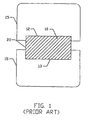
- a conventional implant device disposed between neighboring vertebrae is depicted in FIGs. 1 and 2.
- the implant device contains a pair of engaging elements 20 that typically contain threading 10 to engage the vertebrae.
- a vertebral drill is typically inserted within the surgical wound to drill into the cortical endplate and remove fibrous and nuclear material.
- a vertebral tap may then be used to cut threads into the ends of the neighboring vertebrae.
- the engaging elements tend to be relatively inflexible and substantially undeflectable.
- the engaging elements are typically packed with bone graft to facilitate a spinal fusion.
- the implant device tend to not maintain the "lordosis" or natural curvature of the lower lumbar spine.
- the implant device contains parallel engaging sides 12 and 13 to contact vertebra 15. It is typically required that the engaging sides be parallel to prevent the fusion cage from slipping from the intervertebral space.
- the parallel configuration of the fusion cage tends to alter the lordosis of the spine. Such a loss of lordosis may result in an increased risk to other intervertebral discs located adjacent to the fusion level that may degenerate due to the altered force transmission in the spine.
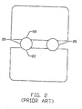
- FIG. 2 depicts a front view of the engaging elements 20 of the implant device.
- the engaging elements are substantially cylindrical and the region of contact between an engaging element and a vertebra is defined by arcuate portion 22.
- the cylindrical geometry of the engaging elements tends to provide a relatively small area of contact between the fusion cage and the vertebrae.
- the weight of the spine creates pressure on the vertebrae that is concentrated proximate the arcuate portions. Subsidence or deformation of the cortical layer of the vertebrae tends to result.
- U.S. Patent No. 5,522,899 to Michelson relates to a spinal implant for placement into the spinal disc space to stabilize the spine and participate in a vertebra to vertebra bony fusion.
- U.S. Patent No. 5,489,308 to Kuslich et al. relates to an implant for use in spinal stabilization that includes a cylindrical body having external threading and radially disposed openings positioned to chip bone into an interior portion of the body when the implant is installed.
- WO-A-97/00054 discloses a spinal implant which includes a pair of engaging plates.
- a spacing device is insertable between the engaging plates to allow the distance between the plates to be altered.
- the spacing device includes an adjusted means having two spacing members disposed longitudinally extending cavity defined by milled grooves.
- a spinal implant is provided that largely eliminates or reduces the aforementioned disadvantages of conventional implant devices.
- An advantage of the invention relates to an intervertebral body fusion device that substantially maintains the natural lordosis of the human spine.
- Another advantage of the invention relates to an intervertebral body fusion device adapted to correct a lateral deviation in the spinal columm.
- Anther advantage of the invention relates to an intervertebral body fusion device that substantially maintains the natural lordosis of the human spine while simultaneously being adapted to correct a lateral deviation in the spinal columm.
- FIGs. 3-5 A preferred embodiment of an interbody fusion implant device 10 for facilitating the formation of a spinal fusion is depicted in FIGs. 3-5.
- a top view of the fusion device is depicted in FIG. 3.
- Fusion device 10 preferably includes a pair of sides or engaging plates 12 and 14 for engaging vertebral bodies 16 and 18.
- the engaging plates may contain curved edges such that the outer face 15 of the plates conforms to the shape of the cross-section of the vertebral bodies as shown in FIG. 3.
- the fusion device has a height 20 defined by the vertical distance between the outer faces 15 of the engaging plates 12 and 14.
- the height 20 of the fusion device is preferably adjustable and may vary along the fusion device between anterior end 22 and posterior end 24 to maintain the natural lordosis of the spine.
- Height 20 may also vary along device 10 from first side 26 to second side 28 to correct for a lateral deviation in the spine as may occur in scoliosis.
- Fusion device 10 preferably further includes an alignment device for adjusting the height 20 so that the natural lordosis of the spine is substantially maintained after the fusion device is implanted.
- the alignment device may be used to adjust the height between the engaging plates proximate the anterior end and independently adjust the height between the engaging plates proximate the posterior end.
- a spinal fusion is typically employed to eliminate pain caused by the motion of degenerative disk material.
- fusion device 10 becomes permanently fixed within the disc space.
- the fusion device is preferably packed with bone graft 40 to promote the growth of bone through and around the fusion device.
- bone graft may be packed between engaging plates 12 and 14 prior to, subsequent to, or during implantation of the fusion device.
- Bone substitute material that is well known to those skilled in the art may be used instead of bone graft.
- a bone harvester kit commercially available from Spine-Tech, Inc. located in Minneapolis, MN, may be used to inject bone graft between the engaging plates.
- the pamphlet entitled “Bone Harvester: Minimally Invasive Bone Harvesting Kit” (available from Spine-Tech, Inc.) details the use of the bone harvesting kit.
- the faces 15 of engaging plates 12 and 14 contain a plurality of openings 34 disposed therein to allow bone development and growth through the engaging plates 12 and 14 and between fusion device 10 and neighboring vertebrae 16 and 18.
- the openings 34 have a combined area that is greater than about 50 percent of the area of face 15 (including the area of the openings 34), more preferably between about 60 percent and about 80 percent of the area of face 15, and more preferably still about 70 percent or more of the area of face 15.
- the fusion device may contain a retaining plate 36 proximate posterior end 24 to provide a backing against which bone graft may be packed and to maintain the bone graft between the engaging plates.
- Retaining plate 36 may be substantially planar and may contain openings to allow bone ingrowth therethrough.
- a removable endcap 25 may be positioned proximate anterior end 22 to contain bone graft within the fusion device and to prevent the migration of bone graft outside the engaging plates.
- the endcap 25 may contain one or more openings for allowing bone ingrowth between a vertebral body and bone graft contained between the engaging plates.
- Endcap 25 is preferably made of a plastic material such as polyethylene that tends to be non-irritating and non-abrasive to the surrounding tissues.
- FIG. 4a shows the relative position of engaging plates 12 and 14 before height 20 has been adjusted with an alignment device to achieve a substantially natural lordosis.
- FIG. 4b shows the relative position of the plates after height 20 has been adjusted and bone graft 40 has been packed between the engaging plates.
- FIG. 4b shows that height 20 is greater in the vicinity of anterior end 22 as compared to posterior end 24 to maintain the natural lordosis of the spinal column.
- the faces 15 of the engaging plates 12 and 14 are preferably planar to provide a relatively large contact area between the engaging plates and the neighboring vertebrae.
- the engaging plates may be non-planar.
- the engaging plates also preferably contain a plurality of spikes or protrusions 38 extending from the face 15 for enhancing an engagement between the vertebra and the engaging plate.
- the protrusions may extend into the vertebra to prevent the fusion device from moving out of the disc space.
- the engaging plates are preferably constructed of titanium or a titanium alloy, although it is to be understood that other materials (e.g., ceramics, metals, carbon composites) may be used.
- the alignment device includes a first strut 30 and a second strut 32 that each extend between engaging plates 12 and 13 along the length of the fusion device from anterior end 22 to posterior end 24.
- a "strut" is taken to mean any support member disposed between the engaging plates to separate the engaging plates.
- Strut 30 preferably extends along the fusion device proximate first side 26.
- Strut 32 is preferably substantially parallel to strut 30 and may extend along the fusion device proximate second side 28.
- the struts 30 and 32 serve to create a predetermined spacing between the engaging plates. The predetermined spacing is preferably such that the height 20 is approximately equal to the height of the disc material that formerly occupied the disc space between the vertebral bodies.
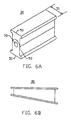
- the strut may have an "I-beam" shape and preferably includes a pair of ends 50.
- the ends 50 may have a lateral width 51 that is greater than that of the sides 53.
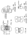
- the ends preferably have a "dovetail” shaped cross-section as shown in FIG. 6a.
- the engaging plates preferably contain elongated slots 60 (shown in FIGs. 7 and 8) sized to receive ends 50 of the first and second struts.
- the slots 60 preferably have a complementary dovetail shape as depicted in FIG. 8 that conforms to the shape of the end 50.
- the struts may be connected to the engaging plates by sliding ends 50 into the slots 60 in a direction from anterior end 22 to posterior end 24 or vice versa.
- the slots are tapered such that their width narrows in a direction from the anterior end to the posterior end as shown in FIG. 7.
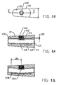
- the ends 50 may be tapered (as shown in FIG. 10) such that the lateral width 51 narrows along the length of the strut.
- the taper of the lateral width of the strut preferably matches that of slot 60.
- the width of the slot proximate the anterior end is preferably sized to allow the strut end to be slid into the slot.
- the width of the slot proximate the posterior end is preferably less than the lateral width 51 of the narrowest portion of end 50.
- the tapering of the slots preferably allows a "locking taper engagement" of the strut ends within the slots.
- a “locking taper engagement” is taken to mean a fixable interference fit formed between end 50 and slot 60 whereby the strut resists dislodgment when force is imparted to the fusion device from the adjacent vertebrae.
- the slots may be tapered such that the width of the slots narrows in a direction from the posterior end to the anterior end.
- the first and second struts preferably each have a predetermined height that defines the height of the fusion device.
- the engaging plates 12 and 14 are preferably adapted to receive struts of various heights to allow height 20 to be varied to fit the needs of the patient.
- a side view of a tapered strut is depicted in FIG. 6b.
- the tapered strut preferably has a height that varies along its length. In this manner, the tapered strut is positionable between the engaging plates 12 and 14 to cause height 20 to decrease in a direction from anterior end 22 to posterior end 24 whereby the natural lordosis of the human spine is maintained by the fusion device.
- the degree of taper of the strut corresponds to a desired lordosis and may vary depending upon the size of the patient.
- the first and second struts have differing heights to cause height 20 to vary between first end 14 and second end 16.
- the fusion device may be used to correct a lateral deviation in the spinal column as may occur in scoliosis.
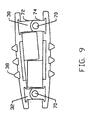
- a front view of a fusion device containing struts having different heights is depicted in FIG. 9.
- Each of the struts preferably contains a hinge pin 70 to allow an upper member 72 of the strut to pivot with respect to a lower member 74 of the strut.
- the struts may be pivoted as shown in FIG. 9 such that the ends of the struts are properly aligned with the slots of the engaging plates when a height difference exists between the first and second struts.
- a discectomy is preferably performed from an anterior approach. All cartilage and soft tissue are preferably removed from the vertebral endplate as would normally be done for placement of a femoral strut graft. Such a procedure is well within the know ledge of a skilled practitioner of the art.
- the engaging plates may be deployed in the disc space between the adjacent vertebrae.
- a distraction force may be applied to the engaging plates using a laminae spreader or similar device to force the vertebrae to a selected height and lordotic alignment.
- the use of a laminae spreader is well known to those skilled in the art.
- the proper heights for the first and second struts may be determined beforehand using x-ray techniques in which the posterior and anterior portions of the intervertebral disc space are examined.
- each strut may be pivoted about hinge pin 70 prior to insertion so that ends 50 are properly aligned for placement into grooves 60.
- Bone graft material is preferably inserted through the anterior end and packed between the engaging plates. Retaining plate 36 preferably prevents the bone graft material from passing through the fusion device during packing. Endcap 25 may then be placed onto the anterior end.
- FIGs. 10-12 An embodiment of the load-sharing fusion device is depicted in FIGs. 10-12.
- a top view of a strut 30 containing a load-sharing member is depicted in FIG. 10.
- FIGs. 11 and 12 depict cross-sectional views of the strut taken along plane V of FIG. 10.
- Load-sharing member 110 is preferably disposed axially through the strut.
- the load-sharing member may be contained in a bore extending into the strut.
- the bore preferably has a width (e.g., diameter) that is greater than that of the load-sharing member to allow sufficient space for the load-sharing member to be deflected.
- the bore is preferably disposed within lower member 74.
- Portion 118 of the upper member may substantially surround the bore and the load-sharing member, thereby allowing attachment of the upper and lower members.
- the load-sharing member is a pin having a substantially circular cross-section. The pin preferably fits loosely within the bore such that its rotational freedom is maintained.
- the pin may be hinge pin 70 about which the upper member 72 pivots with respect to the lower member 74.
- the load-sharing member preferably contains an indention 114 forming a substantially planar surface about which the load-sharing member may be deflected.
- a connector 112 preferably extends through an opening 116 in the end 50 of the strut.
- the connector preferably fixes the load-sharing member to the upper member 72 and may contact the load-sharing member at fulcrum point 126, which is preferably located on the planar surface formed by indention 114.
- Connector 122 is preferably a set screw, and opening 116 preferably contains threading for engaging the set screw.
- FIG. 11 depicts the strut in an "unloaded" position whereby a predetemined spacing 122 exists between upper member 72 and portion 120 of lower member 74.
- the predetermined spacing 122 may be adjusted by altering the location of connector 112 within opening 116. For instance, the screw may be rotated through opening 116 to increase spacing 122.
- the load-sharing member preferably remains substantially undeflected in the unloaded position.
- force is preferably imparted from connector 112 to the load-sharing member at fulcrum point 126.
- the compressive force is preferably sufficient to cause deflection of the load-sharing member and movement of upper member 72 toward portion 120 of the lower member such that predetermined spacing 122 is decreased.
- the deflection of the load-sharing member may force portion 118 of the upper member into a cavity 115 formed within the axial bore.
- the load-sharing member is preferably deflected in a three point bending arrangement as shown in FIG. 19.
- FIG. 12 depicts the strut in the "loaded" position with the load-sharing member deflected.
- the predetermined spacing 22 is preferably adjustable and may be adjusted to set the maximum strain that can be imparted to the load-sharing member.
- the upper member 72 contacts portion 120, thereby inhibiting further strain on the load-sharing member. In this manner, the maximum amount of strain on the load-sharing member can be limited to reduce the possibility that the member will experience fatigue failure.
- the load-sharing member may be constructed of any of a variety of metals or alloys.
- the load-sharing member is constructed of titanium or a titanium alloy.
- the material properties and cross-sectional area of the load-sharing member are preferably controlled to allow a predetermined amount of stress to occur across the fusion device.
- the horizontal distance 124 or moment arm between fulcrum point 126 and support point 128 on the lower member is preferably selected such that the fusion device has an "effective" modulus of elasticity in the vicinity of the modulus of elasticity of bone to facilitate bone development.
- the "effective" modulus of elasticity of the fusion device is taken to mean the ratio of stress to strain across the fusion device in a direction along height 20 as the device moves from the unloaded position to the loaded position upon receiving a compressive force.
- "in the vicinity of the modulus of elasticity of bone” is taken to mean a Young's modulus between about 3 GPa and about 25 GPa.
- the effective modulus of the fusion device is between about 16 GPa and about 20 GPa.
- the stresses exerted onto the spinal column are preferably shared by the fusion device and surrounding bone graft. As the spinal fusion develops, the proportion of stress experienced by the surrounding bone material preferably increases and the required load on the fusion device preferably decreases. After completion of the fusion, the fusion device preferably remains in the unloaded position during normal daily activity of the patient.
- Fusion device 10 preferably provides a relatively large contact area between the engaging plates and the vertebral bodies defining the disc space occupied by the fusion device.
- FIG. 13 depicts a top view of an embodiment of a fusion device of the present invention.
- FIG. 14 depict a cross-sectional view of the fusion device taken along plane VI of FIG. 13.
- Depicted in FIGs. 15-17 is a conventional fusion cage such as that described in U.S. Patent No. 4,961,740 to Ray et al.
- the devices in FIGs. 13-17 are sized for use in the L3-L4 disc space of an average size middle-aged female. Dimensions of the fusion devices are indicated in millimeters.
- the "effective contact area" between an engaging plate and a vertebral body may be calculated by subtracting the fenestration area, a (i.e., the combined area of the openings 34 intended for bone ingrowth), from the total contact area, A (the area of the face 15 including the area of the openings 34).
- the total contact area and the fenestration area of the fusion device in FIGs. 13 and 14 is 581 mm 2 and 96 mm 2 , respectively. Therefore, the effective contact area between the engaging plate and the vertebra is 485 mm 2 .
- the maximum axial compressive forces in the lumbar spine resulting from everyday activity were estimated to be 3200 N in a paper entitled "The BAKTM Interbody Fusion: An Alternative Solution” by Bagby et al. and available from Spine Tech, Inc. in Minneapolis Minnesota (see page 3, bottom paragraph).
- the stress per unit area is calculated to be 18.8 N/mm 2 for the fusion cage depicted in FIGs. 15-17 as compared to 6.6 N/mm 2 for the fusion device depicted in FIG. 13 and FIG 14. It is believed that such a reduction in stress per unit area will result in a significant reduction in post surgical subsidence at the interface of the fusion device and vertebral body.
- the loss of disc height is estimated to be about 1-3 mm at one month follow-up when conventional devices such as that depicted in FIGs. 15-17 are employed.
- a discectomy is preferably performed from an anterior approach. All cartilage and soft tissue are preferably removed from the vertebral endplate as would normally be done for placement for a femoral strut graft. Such a procedure is well within the knowledge of a skilled practitioner of the art.
- the engaging plates may be deployed in the disc space between adjacent vertebrae.
Landscapes
- Health & Medical Sciences (AREA)
- Engineering & Computer Science (AREA)
- Biomedical Technology (AREA)
- Orthopedic Medicine & Surgery (AREA)
- Neurology (AREA)
- Heart & Thoracic Surgery (AREA)
- Oral & Maxillofacial Surgery (AREA)
- Transplantation (AREA)
- Cardiology (AREA)
- Vascular Medicine (AREA)
- Life Sciences & Earth Sciences (AREA)
- Animal Behavior & Ethology (AREA)
- General Health & Medical Sciences (AREA)
- Public Health (AREA)
- Veterinary Medicine (AREA)
- Prostheses (AREA)
- Surgical Instruments (AREA)
- Lining Or Joining Of Plastics Or The Like (AREA)
Abstract
Description
- The present invention generally relates to apparatus for promoting an intervertebral fusion, and more particularly to an apparatus for insertion into a space between adjacent vertebrae to facilitate an intervertebral fusion while maintaining a substantially natural lordosis of the human spine.
- Intervertebral discs that become degenerated due to various factors such as trauma or aging typically have to be partially or fully removed. Removal of an intervertebral disc can destabilize the spine, making it necessary to replace the vertebral disc to maintain the height of the spine and to restore stability. Spinal implants are often used to prevent collapse of the spine and promote fusion. U.S. Serial No. 08/740,123 filed October 24, 1996 relates to methods and apparatus for facilitating a spinal fusion.
- After an intervertebral disc is removed, an implant device is typically inserted between neighboring vertebrae to maintain normal disc spacing and restore spinal stability, thereby facilitating an intervertebral fusion. A conventional implant device disposed between neighboring vertebrae is depicted in FIGs. 1 and 2. The implant device contains a pair of
engaging elements 20 that typically containthreading 10 to engage the vertebrae. Prior to inserting the engaging elements, a vertebral drill is typically inserted within the surgical wound to drill into the cortical endplate and remove fibrous and nuclear material. A vertebral tap may then be used to cut threads into the ends of the neighboring vertebrae. The engaging elements tend to be relatively inflexible and substantially undeflectable. The engaging elements are typically packed with bone graft to facilitate a spinal fusion. - Conventional implant devices tend to not maintain the "lordosis" or natural curvature of the lower lumbar spine. As shown in FIG. 1, the implant device contains parallel
engaging sides vertebra 15. It is typically required that the engaging sides be parallel to prevent the fusion cage from slipping from the intervertebral space. The parallel configuration of the fusion cage tends to alter the lordosis of the spine. Such a loss of lordosis may result in an increased risk to other intervertebral discs located adjacent to the fusion level that may degenerate due to the altered force transmission in the spine. - FIG. 2 depicts a front view of the
engaging elements 20 of the implant device. The engaging elements are substantially cylindrical and the region of contact between an engaging element and a vertebra is defined byarcuate portion 22. The cylindrical geometry of the engaging elements tends to provide a relatively small area of contact between the fusion cage and the vertebrae. The weight of the spine creates pressure on the vertebrae that is concentrated proximate the arcuate portions. Subsidence or deformation of the cortical layer of the vertebrae tends to result. - U.S. Patent No. 5,522,899 to Michelson relates to a spinal implant for placement into the spinal disc space to stabilize the spine and participate in a vertebra to vertebra bony fusion. U.S. Patent No. 5,489,308 to Kuslich et al. relates to an implant for use in spinal stabilization that includes a cylindrical body having external threading and radially disposed openings positioned to chip bone into an interior portion of the body when the implant is installed.
- The above-mentioned prior methods and systems inadequately address, among other things, the need to maintain the natural lordosis of the spine. It is therefore desirable that an improved spinal implant be derived for facilitating an intervertebral body fusion.
- WO-A-97/00054 discloses a spinal implant which includes a pair of engaging plates. A spacing device is insertable between the engaging plates to allow the distance between the plates to be altered. The spacing device includes an adjusted means having two spacing members disposed longitudinally extending cavity defined by milled grooves.
- In accordance with the present invention, a spinal implant is provided that largely eliminates or reduces the aforementioned disadvantages of conventional implant devices.
- The invention is defined in the appended claims.
- An advantage of the invention relates to an intervertebral body fusion device that substantially maintains the natural lordosis of the human spine.
- Another advantage of the invention relates to an intervertebral body fusion device adapted to correct a lateral deviation in the spinal columm.
- Anther advantage of the invention relates to an intervertebral body fusion device that substantially maintains the natural lordosis of the human spine while simultaneously being adapted to correct a lateral deviation in the spinal columm.
- Further advantages of the present invention will become apparent to those skilled in the art with the benefit of the following detailed description of the preferred embodiments and upon reference to the accompanying drawings in which:
- FIG. 1 depicts a conventional intervertebral body fusion implant positioned between neighboring vertebrae;
- FIG. 2 depicts another conventional intervertebral body fusion implant that includes a pair of cylindrical members positioned between neighboring vertebrae;
- FIG. 3 depicts a top view of a fusion device located on a vertebral body;
- FIG. 4a depicts a cross-sectional view of the fusion device of FIG. 3 taken along plane 1;
- FIG. 4b depicts a cross-sectional view of the fusion of FIG. 3 device taken along plane 1 wherein the fusion device contains bone graft and has been adjusted to maintain a substantially natural lordosis;
- FIG. 5 depicts a front view of a fusion device;
- FIG. 6a depicts a perspective view of a strut;
- FIG. 6b depicts a side view of a tapered strut;
- FIG. 7 depicts a top view of a fusion device;
- FIG. 8 depicts a front view of a pair of engaging plates;
- FIG. 9 depicts a front view of a fusion device having pivotable struts;
- FIG. 10 depicts a top view of a strut having a tapered end;
- FIG. 11 depicts a cross-sectional view taken along plane V of FIG. 10 of the strut in an unloaded position;
- FIG. 12 depicts a cross-sectional view taken along plane V of FIG. 10 of the strut in a loaded positon,
- FIG. 13 depicts a top view of a fusion device located on a vertebral body;
- FIG. 14 depicts a cross-sectional view of the fusion device taken along plane VI of FIG. 3;
- FIG. 15 depicts a top view of a conventional fusion cage having a pair of cylindrical elements disposed on a vertebra;
- FIG. 16 depicts a side view of one of the cylindrical elements in FIG. 15 disposed between neighboring vertebrae;
- FIG. 17 depicts a front view of the cylindrical element in FIG. 16;
-
- While the invention is susceptible to various modifications and alternative forms, specific embodiments thereof are shown by way of example in the drawings and will herein be described in detail. It should be understood, however, that the drawings and detailed description thereto are not intended to limit the invention to the particular form disclosed, but on the contrary, the intention is to cover all modifications, equivalents and alternatives falling within the scope of the present invention as defined by the appended claims.
- A preferred embodiment of an interbody
fusion implant device 10 for facilitating the formation of a spinal fusion is depicted in FIGs. 3-5. A top view of the fusion device is depicted in FIG. 3.Fusion device 10 preferably includes a pair of sides or engagingplates vertebral bodies outer face 15 of the plates conforms to the shape of the cross-section of the vertebral bodies as shown in FIG. 3. The fusion device has aheight 20 defined by the vertical distance between the outer faces 15 of the engagingplates height 20 of the fusion device is preferably adjustable and may vary along the fusion device betweenanterior end 22 andposterior end 24 to maintain the natural lordosis of the spine.Height 20 may also vary alongdevice 10 fromfirst side 26 tosecond side 28 to correct for a lateral deviation in the spine as may occur in scoliosis.Fusion device 10 preferably further includes an alignment device for adjusting theheight 20 so that the natural lordosis of the spine is substantially maintained after the fusion device is implanted. The alignment device may be used to adjust the height between the engaging plates proximate the anterior end and independently adjust the height between the engaging plates proximate the posterior end. - A spinal fusion is typically employed to eliminate pain caused by the motion of degenerative disk material. Upon successful fusion,
fusion device 10 becomes permanently fixed within the disc space. The fusion device is preferably packed withbone graft 40 to promote the growth of bone through and around the fusion device. Such bone graft may be packed between engagingplates - In an embodiment of the invention, the
faces 15 of engagingplates openings 34 disposed therein to allow bone development and growth through the engagingplates fusion device 10 and neighboringvertebrae openings 34 have a combined area that is greater than about 50 percent of the area of face 15 (including the area of the openings 34), more preferably between about 60 percent and about 80 percent of the area offace 15, and more preferably still about 70 percent or more of the area offace 15. - The fusion device may contain a retaining
plate 36 proximateposterior end 24 to provide a backing against which bone graft may be packed and to maintain the bone graft between the engaging plates. Retainingplate 36 may be substantially planar and may contain openings to allow bone ingrowth therethrough. Aremovable endcap 25 may be positioned proximateanterior end 22 to contain bone graft within the fusion device and to prevent the migration of bone graft outside the engaging plates. Theendcap 25 may contain one or more openings for allowing bone ingrowth between a vertebral body and bone graft contained between the engaging plates.Endcap 25 is preferably made of a plastic material such as polyethylene that tends to be non-irritating and non-abrasive to the surrounding tissues. - A cross section of the fusion device taken through plane 1 of FIG. 3 is depicted in FIG. 4a and FIG. 4b. FIG. 4a shows the relative position of engaging
plates height 20 has been adjusted with an alignment device to achieve a substantially natural lordosis. FIG. 4b shows the relative position of the plates afterheight 20 has been adjusted andbone graft 40 has been packed between the engaging plates. FIG. 4b shows thatheight 20 is greater in the vicinity ofanterior end 22 as compared toposterior end 24 to maintain the natural lordosis of the spinal column. The faces 15 of the engagingplates protrusions 38 extending from theface 15 for enhancing an engagement between the vertebra and the engaging plate. The protrusions may extend into the vertebra to prevent the fusion device from moving out of the disc space. The engaging plates are preferably constructed of titanium or a titanium alloy, although it is to be understood that other materials (e.g., ceramics, metals, carbon composites) may be used. - A front view of the fusion implant device is depicted in FIG. 5. In an embodiment of the invention, the alignment device includes a
first strut 30 and asecond strut 32 that each extend between engagingplates anterior end 22 toposterior end 24. As described herein, a "strut" is taken to mean any support member disposed between the engaging plates to separate the engaging plates.Strut 30 preferably extends along the fusion device proximatefirst side 26.Strut 32 is preferably substantially parallel to strut 30 and may extend along the fusion device proximatesecond side 28. Thestruts height 20 is approximately equal to the height of the disc material that formerly occupied the disc space between the vertebral bodies. - A perspective view of an embodiment of the strut is depicted in FIG. 6a. The strut may have an "I-beam" shape and preferably includes a pair of ends 50. The ends 50 may have a
lateral width 51 that is greater than that of thesides 53. The ends preferably have a "dovetail" shaped cross-section as shown in FIG. 6a. The engaging plates preferably contain elongated slots 60 (shown in FIGs. 7 and 8) sized to receive ends 50 of the first and second struts. Theslots 60 preferably have a complementary dovetail shape as depicted in FIG. 8 that conforms to the shape of theend 50. The struts may be connected to the engaging plates by slidingends 50 into theslots 60 in a direction fromanterior end 22 toposterior end 24 or vice versa. - In an embodiment, the slots are tapered such that their width narrows in a direction from the anterior end to the posterior end as shown in FIG. 7. The ends 50 may be tapered (as shown in FIG. 10) such that the
lateral width 51 narrows along the length of the strut. The taper of the lateral width of the strut preferably matches that ofslot 60. The width of the slot proximate the anterior end is preferably sized to allow the strut end to be slid into the slot. The width of the slot proximate the posterior end is preferably less than thelateral width 51 of the narrowest portion ofend 50. The tapering of the slots preferably allows a "locking taper engagement" of the strut ends within the slots. A "locking taper engagement" is taken to mean a fixable interference fit formed betweenend 50 andslot 60 whereby the strut resists dislodgment when force is imparted to the fusion device from the adjacent vertebrae. In an alternate embodiment, the slots may be tapered such that the width of the slots narrows in a direction from the posterior end to the anterior end. - The first and second struts preferably each have a predetermined height that defines the height of the fusion device. The engaging
plates height 20 to be varied to fit the needs of the patient. A side view of a tapered strut is depicted in FIG. 6b. The tapered strut preferably has a height that varies along its length. In this manner, the tapered strut is positionable between the engagingplates height 20 to decrease in a direction fromanterior end 22 toposterior end 24 whereby the natural lordosis of the human spine is maintained by the fusion device. The degree of taper of the strut corresponds to a desired lordosis and may vary depending upon the size of the patient. - In an embodiment, the first and second struts have differing heights to cause
height 20 to vary betweenfirst end 14 andsecond end 16. In this manner, the fusion device may be used to correct a lateral deviation in the spinal column as may occur in scoliosis. A front view of a fusion device containing struts having different heights is depicted in FIG. 9. Each of the struts preferably contains ahinge pin 70 to allow anupper member 72 of the strut to pivot with respect to alower member 74 of the strut. In this manner, the struts may be pivoted as shown in FIG. 9 such that the ends of the struts are properly aligned with the slots of the engaging plates when a height difference exists between the first and second struts. - To install the fusion device, a discectomy is preferably performed from an anterior approach. All cartilage and soft tissue are preferably removed from the vertebral endplate as would normally be done for placement of a femoral strut graft. Such a procedure is well within the know ledge of a skilled practitioner of the art. The engaging plates may be deployed in the disc space between the adjacent vertebrae. A distraction force may be applied to the engaging plates using a laminae spreader or similar device to force the vertebrae to a selected height and lordotic alignment. The use of a laminae spreader is well known to those skilled in the art. The proper heights for the first and second struts may be determined beforehand using x-ray techniques in which the posterior and anterior portions of the intervertebral disc space are examined.
- Appropriately sized and tapered struts are preferably slipped into
slots 60 and tapped until a locking taper engagement is achieved between the strut ends and the slots. If struts of differing heights are used to correct for a lateral deviation in the spinal columm, each strut may be pivoted abouthinge pin 70 prior to insertion so that ends 50 are properly aligned for placement intogrooves 60. Bone graft material is preferably inserted through the anterior end and packed between the engaging plates. Retainingplate 36 preferably prevents the bone graft material from passing through the fusion device during packing.Endcap 25 may then be placed onto the anterior end. - An embodiment of the load-sharing fusion device is depicted in FIGs. 10-12. A top view of a
strut 30 containing a load-sharing member is depicted in FIG. 10. FIGs. 11 and 12 depict cross-sectional views of the strut taken along plane V of FIG. 10. Load-sharingmember 110 is preferably disposed axially through the strut. The load-sharing member may be contained in a bore extending into the strut. The bore preferably has a width (e.g., diameter) that is greater than that of the load-sharing member to allow sufficient space for the load-sharing member to be deflected. The bore is preferably disposed withinlower member 74.Portion 118 of the upper member may substantially surround the bore and the load-sharing member, thereby allowing attachment of the upper and lower members. In an embodiment, the load-sharing member is a pin having a substantially circular cross-section. The pin preferably fits loosely within the bore such that its rotational freedom is maintained. The pin may behinge pin 70 about which theupper member 72 pivots with respect to thelower member 74. The load-sharing member preferably contains anindention 114 forming a substantially planar surface about which the load-sharing member may be deflected. - A
connector 112 preferably extends through anopening 116 in theend 50 of the strut. The connector preferably fixes the load-sharing member to theupper member 72 and may contact the load-sharing member atfulcrum point 126, which is preferably located on the planar surface formed byindention 114.Connector 122 is preferably a set screw, andopening 116 preferably contains threading for engaging the set screw. FIG. 11 depicts the strut in an "unloaded" position whereby apredetemined spacing 122 exists betweenupper member 72 andportion 120 oflower member 74. Thepredetermined spacing 122 may be adjusted by altering the location ofconnector 112 withinopening 116. For instance, the screw may be rotated throughopening 116 to increasespacing 122. The load-sharing member preferably remains substantially undeflected in the unloaded position. - Upon application of a compressive force onto the
end 50 of theupper member 72, force is preferably imparted fromconnector 112 to the load-sharing member atfulcrum point 126. The compressive force is preferably sufficient to cause deflection of the load-sharing member and movement ofupper member 72 towardportion 120 of the lower member such thatpredetermined spacing 122 is decreased. The deflection of the load-sharing member may forceportion 118 of the upper member into a cavity 115 formed within the axial bore. The load-sharing member is preferably deflected in a three point bending arrangement as shown in FIG. 19. - FIG. 12 depicts the strut in the "loaded" position with the load-sharing member deflected. The
predetermined spacing 22 is preferably adjustable and may be adjusted to set the maximum strain that can be imparted to the load-sharing member. When the load-sharing member has been deflected a vertical distance equal topredetermined spacing 22, theupper member 72contacts portion 120, thereby inhibiting further strain on the load-sharing member. In this manner, the maximum amount of strain on the load-sharing member can be limited to reduce the possibility that the member will experience fatigue failure. - The load-sharing member may be constructed of any of a variety of metals or alloys. In a preferred embodiment, the load-sharing member is constructed of titanium or a titanium alloy. The material properties and cross-sectional area of the load-sharing member are preferably controlled to allow a predetermined amount of stress to occur across the fusion device. The
horizontal distance 124 or moment arm betweenfulcrum point 126 andsupport point 128 on the lower member is preferably selected such that the fusion device has an "effective" modulus of elasticity in the vicinity of the modulus of elasticity of bone to facilitate bone development. The "effective" modulus of elasticity of the fusion device is taken to mean the ratio of stress to strain across the fusion device in a direction alongheight 20 as the device moves from the unloaded position to the loaded position upon receiving a compressive force. As described herein, "in the vicinity of the modulus of elasticity of bone" is taken to mean a Young's modulus between about 3 GPa and about 25 GPa. In an embodiment, the effective modulus of the fusion device is between about 16 GPa and about 20 GPa. The paper entitled "Variation of Young's Modulus and Hardness in Human Lumbar Vertebrae Measured by Nanoindentation" by Marcel Roy and Jac-Young Rho (Department of Biomedical Engineering, University of Memphis, Memphis, TN), and Ting Y. Tsui and George M. Pharr (Department of Materials Science, Rice University, Houston, TX) relates to the mechanical properties of bone - The stresses exerted onto the spinal column are preferably shared by the fusion device and surrounding bone graft. As the spinal fusion develops, the proportion of stress experienced by the surrounding bone material preferably increases and the required load on the fusion device preferably decreases. After completion of the fusion, the fusion device preferably remains in the unloaded position during normal daily activity of the patient.
-
Fusion device 10 preferably provides a relatively large contact area between the engaging plates and the vertebral bodies defining the disc space occupied by the fusion device. FIG. 13 depicts a top view of an embodiment of a fusion device of the present invention. FIG. 14 depict a cross-sectional view of the fusion device taken along plane VI of FIG. 13. Depicted in FIGs. 15-17 is a conventional fusion cage such as that described in U.S. Patent No. 4,961,740 to Ray et al. The devices in FIGs. 13-17 are sized for use in the L3-L4 disc space of an average size middle-aged female. Dimensions of the fusion devices are indicated in millimeters. - The "effective contact area" between an engaging plate and a vertebral body may be calculated by subtracting the fenestration area, a (i.e., the combined area of the
openings 34 intended for bone ingrowth), from the total contact area, A (the area of theface 15 including the area of the openings 34). The total contact area and the fenestration area of the fusion device in FIGs. 13 and 14 is 581 mm2 and 96 mm2, respectively. Therefore, the effective contact area between the engaging plate and the vertebra is 485 mm2. - For the fusion cage depicted in FIGs. 15-17, it is assumed that threads on the outer surface of the fusion cage penetrate into the vertebra a total of 3 mm per side as recommended by the manufacturer. It should be noted that such penetration is often difficult to achieve. In addition, the cortical layer of a vertebral body is often only 1-2 mm thick. Each of the cylindrical elements of the fusion cage has a total contact area of 283.5 mm2 and a fenestration area of 198.5 mm2. Therefore, the combined effective contact area of both of the cylindrical elements is 170 mm2. If the threads of the fusion cage penetrate into the vertebra a distance less than 3 mm per side, the contact area will be less than that calculated above.
- The maximum axial compressive forces in the lumbar spine resulting from everyday activity were estimated to be 3200 N in a paper entitled "The BAK™ Interbody Fusion: An Innovative Solution" by Bagby et al. and available from Spine Tech, Inc. in Minneapolis Minnesota (see page 3, bottom paragraph). For a 3200 N compressive force, the stress per unit area is calculated to be 18.8 N/mm2 for the fusion cage depicted in FIGs. 15-17 as compared to 6.6 N/mm2 for the fusion device depicted in FIG. 13 and FIG 14. It is believed that such a reduction in stress per unit area will result in a significant reduction in post surgical subsidence at the interface of the fusion device and vertebral body. Typically, the loss of disc height is estimated to be about 1-3 mm at one month follow-up when conventional devices such as that depicted in FIGs. 15-17 are employed.
- To install the fusion devices, a discectomy is preferably performed from an anterior approach. All cartilage and soft tissue are preferably removed from the vertebral endplate as would normally be done for placement for a femoral strut graft. Such a procedure is well within the knowledge of a skilled practitioner of the art. The engaging plates may be deployed in the disc space between adjacent vertebrae.
Claims (12)
- A spinal implant for facilitating a fusion between neighboring vertebrae of a human spine, comprising :characterized by the fact that the strut (30) comprises an upper and a lower member (72, 74) received in said slot (60) and attached to each other by a deflectable load-sharing member (110) so that the strut (30) is deflectable to separate the engaging plates (12, 14) and to cause stress to be applied to bone in the vicinity of the implant.an anterior end opposite a posterior end ;a pair of engaging plates (12, 14) adapted to fit between and engage the vertebrae to maintain a disk space between the vertebrae during use ;a strut (30) positionable between the engaging plates, the strut being adapted to separate the engaging plates during use such that a height (20) exists therebetween, the height being adjustable such that the height proximate the anterior end differs from the height proximate the posterior end to substantially maintain a natural curvature of the human spine during use; andeach of the engaging plates comprising a slot (60),
- The spinal implant of claim 1 wherein the strut is operable during use to adjust the height between the engaging plates (12, 14) proximate the anterior end and simultaneously adjust the height between the engaging plates proximate the posterior end.
- The spinal implant of claim 1 wherein the engaging plates (12, 14) are substantially planar so as to inhibit subsidence of the vertebrae.
- The spinal implant of claim 1 wherein the engaging plates comprise a plurality of openings (34) to allow bone growth to occur through the engaging plates.
- The spinal implant of claim 1 wherein the engaging plates comprise a plurality of openings (34), and further comprising bone graft (40) adapted to be packed between the engaging plates.
- The spinal implant of claim 1 wherein the strut comprises a hinge (70) to allow said upper member (72) of the strut to pivot with respect to said lower member (74) of the strut.
- The spinal implant of claim 1, further comprising protrusions (38) extending form at least one of the engaging plates for enhancing an engagement between the vertebra and the engaging plate.
- The spinal implant of claim 1, further comprising a retaining plate (36) proximate the posterior end for maintaining bone graft (40) between the engaging plates.
- The spinal implant of claim 1, further comprising a removable end cap (25) proximate the anterior end for maintaining bone graft between the engaging plates.
- The spinal implant of claim 1, wherein the slot (60) has a substantially dovetail-shaped cross-section for receiving an end of the strut.
- The spinal implant of claim 1, wherein each of the engaging plates (12, 14) comprises a slot (60) for receiving an end of the strut, the slot having a width that narrows in a direction from the anterior end to the posterior end, the width of the slot proximate the posterior end being less than a width of the end of the strut such that a locking taper engagement is formable between the slot and the end of the strut.
- The spinal implant of claim 1, wherein the strut (30) comprises a height (20) that varies along its length such that the height between the engaging plates differs between the anterior end and the posterior end.
Applications Claiming Priority (5)
| Application Number | Priority Date | Filing Date | Title |
|---|---|---|---|
| US847172 | 1997-05-01 | ||
| US08/847,172 US6045579A (en) | 1997-05-01 | 1997-05-01 | Adjustable height fusion device |
| US46759 | 1998-03-24 | ||
| US09/046,759 US6641614B1 (en) | 1997-05-01 | 1998-03-24 | Multi-variable-height fusion device |
| PCT/US1998/008832 WO1998048739A1 (en) | 1997-05-01 | 1998-04-30 | Multi-variable height fusion device |
Publications (2)
| Publication Number | Publication Date |
|---|---|
| EP0977526A1 EP0977526A1 (en) | 2000-02-09 |
| EP0977526B1 true EP0977526B1 (en) | 2003-09-17 |
Family
ID=26724269
Family Applications (1)
| Application Number | Title | Priority Date | Filing Date |
|---|---|---|---|
| EP98920096A Expired - Lifetime EP0977526B1 (en) | 1997-05-01 | 1998-04-30 | Multi-variable height fusion device |
Country Status (9)
| Country | Link |
|---|---|
| US (2) | US6641614B1 (en) |
| EP (1) | EP0977526B1 (en) |
| JP (1) | JP4166288B2 (en) |
| KR (1) | KR20010012139A (en) |
| AT (1) | ATE249795T1 (en) |
| AU (1) | AU745978B2 (en) |
| CA (1) | CA2287899A1 (en) |
| DE (1) | DE69818246T2 (en) |
| WO (1) | WO1998048739A1 (en) |
Cited By (3)
| Publication number | Priority date | Publication date | Assignee | Title |
|---|---|---|---|---|
| US9216096B2 (en) | 2010-03-16 | 2015-12-22 | Pinnacle Spine Group, Llc | Intervertebral implants and related tools |
| US9380932B1 (en) | 2011-11-02 | 2016-07-05 | Pinnacle Spine Group, Llc | Retractor devices for minimally invasive access to the spine |
| US10070970B2 (en) | 2013-03-14 | 2018-09-11 | Pinnacle Spine Group, Llc | Interbody implants and graft delivery systems |
Families Citing this family (468)
| Publication number | Priority date | Publication date | Assignee | Title |
|---|---|---|---|---|
| DE19807236C2 (en) | 1998-02-20 | 2000-06-21 | Biedermann Motech Gmbh | Intervertebral implant |
| FR2794968B1 (en) * | 1999-06-17 | 2002-09-06 | Dimso Sa | INTERSOMATIC RACHIDIAN IMPLANT WITH HIGHLIGHTS |
| US6193757B1 (en) | 1998-10-29 | 2001-02-27 | Sdgi Holdings, Inc. | Expandable intervertebral spacers |
| US6206923B1 (en) | 1999-01-08 | 2001-03-27 | Sdgi Holdings, Inc. | Flexible implant using partially demineralized bone |
| US6113638A (en) * | 1999-02-26 | 2000-09-05 | Williams; Lytton A. | Method and apparatus for intervertebral implant anchorage |
| FR2790945B1 (en) * | 1999-03-19 | 2001-08-03 | Von Bunau Frederic Hansen | INTERSOMATIC VERTEBRAL IMPLANT |
| ATE291398T1 (en) * | 1999-06-04 | 2005-04-15 | Sdgi Holdings Inc | ARTIFICIAL INTERVERBEL IMPLANT |
| DE29924985U1 (en) | 1999-07-02 | 2007-09-06 | Spine Solutions Inc. | Intervertebral implant |
| US6261291B1 (en) | 1999-07-08 | 2001-07-17 | David J. Talaber | Orthopedic implant assembly |
| WO2001015637A1 (en) * | 1999-08-27 | 2001-03-08 | Synthes Ag Chur | Intervertebral implant |
| EP1645248B8 (en) | 2000-02-04 | 2010-06-16 | Warsaw Orthopedic, Inc. | Expandable interbody spinal fusion implant having pivotally attached blocker |
| US6814756B1 (en) * | 2000-02-04 | 2004-11-09 | Gary K. Michelson | Expandable threaded arcuate interbody spinal fusion implant with lordotic configuration during insertion |
| US6709458B2 (en) | 2000-02-04 | 2004-03-23 | Gary Karlin Michelson | Expandable push-in arcuate interbody spinal fusion implant with tapered configuration during insertion |
| US6716247B2 (en) | 2000-02-04 | 2004-04-06 | Gary K. Michelson | Expandable push-in interbody spinal fusion implant |
| US6500205B1 (en) | 2000-04-19 | 2002-12-31 | Gary K. Michelson | Expandable threaded arcuate interbody spinal fusion implant with cylindrical configuration during insertion |
| US6808537B2 (en) * | 2000-07-07 | 2004-10-26 | Gary Karlin Michelson | Expandable implant with interlocking walls |
| US7118579B2 (en) * | 2001-02-04 | 2006-10-10 | Sdgi Holdings, Inc. | Instrumentation for inserting an expandable interbody spinal fusion implant |
| US7169182B2 (en) | 2001-07-16 | 2007-01-30 | Spinecore, Inc. | Implanting an artificial intervertebral disc |
| US8940047B2 (en) * | 2001-02-15 | 2015-01-27 | Spinecore, Inc. | Intervertebral spacer device having recessed notch pairs for manipulation using a surgical tool |
| US7223291B2 (en) * | 2001-07-16 | 2007-05-29 | Spinecore, Inc. | Intervertebral spacer device having engagement hole pairs for manipulation using a surgical tool |
| US6863689B2 (en) * | 2001-07-16 | 2005-03-08 | Spinecore, Inc. | Intervertebral spacer having a flexible wire mesh vertebral body contact element |
| US6673113B2 (en) | 2001-10-18 | 2004-01-06 | Spinecore, Inc. | Intervertebral spacer device having arch shaped spring elements |
| US7128760B2 (en) | 2001-03-27 | 2006-10-31 | Warsaw Orthopedic, Inc. | Radially expanding interbody spinal fusion implants, instrumentation, and methods of insertion |
| FR2824261B1 (en) | 2001-05-04 | 2004-05-28 | Ldr Medical | INTERVERTEBRAL DISC PROSTHESIS AND IMPLEMENTATION METHOD AND TOOLS |
| US20070198092A1 (en) * | 2001-07-16 | 2007-08-23 | Spinecore, Inc. | System for inserting artificial intervertebral discs |
| US7491241B2 (en) * | 2001-07-16 | 2009-02-17 | Spinecore, Inc. | Intervertebral spacer device having recessed notch pairs for manipulation using a surgical tool |
| US7713302B2 (en) | 2001-10-01 | 2010-05-11 | Spinecore, Inc. | Intervertebral spacer device utilizing a spirally slotted belleville washer having radially spaced concentric grooves |
| US7771477B2 (en) | 2001-10-01 | 2010-08-10 | Spinecore, Inc. | Intervertebral spacer device utilizing a belleville washer having radially spaced concentric grooves |
| US6648917B2 (en) * | 2001-10-17 | 2003-11-18 | Medicinelodge, Inc. | Adjustable bone fusion implant and method |
| EP1482877B1 (en) * | 2002-03-11 | 2007-05-30 | Spinal Concepts Inc. | Instrumentation for implanting spinal implant devices |
| DE60334897D1 (en) | 2002-03-30 | 2010-12-23 | Infinity Orthopaedics Co Ltd | Medical Intervertebral Device |
| US20080027548A9 (en) | 2002-04-12 | 2008-01-31 | Ferree Bret A | Spacerless artificial disc replacements |
| US8038713B2 (en) | 2002-04-23 | 2011-10-18 | Spinecore, Inc. | Two-component artificial disc replacements |
| US6793678B2 (en) | 2002-06-27 | 2004-09-21 | Depuy Acromed, Inc. | Prosthetic intervertebral motion disc having dampening |
| GB0223327D0 (en) * | 2002-10-08 | 2002-11-13 | Ranier Ltd | Artificial spinal disc |
| US7497859B2 (en) * | 2002-10-29 | 2009-03-03 | Kyphon Sarl | Tools for implanting an artificial vertebral disk |
| US6966929B2 (en) * | 2002-10-29 | 2005-11-22 | St. Francis Medical Technologies, Inc. | Artificial vertebral disk replacement implant with a spacer |
| US7833246B2 (en) | 2002-10-29 | 2010-11-16 | Kyphon SÀRL | Interspinous process and sacrum implant and method |
| US7273496B2 (en) * | 2002-10-29 | 2007-09-25 | St. Francis Medical Technologies, Inc. | Artificial vertebral disk replacement implant with crossbar spacer and method |
| FR2846550B1 (en) * | 2002-11-05 | 2006-01-13 | Ldr Medical | INTERVERTEBRAL DISC PROSTHESIS |
| US7828849B2 (en) | 2003-02-03 | 2010-11-09 | Warsaw Orthopedic, Inc. | Expanding interbody implant and articulating inserter and method |
| US20040158254A1 (en) * | 2003-02-12 | 2004-08-12 | Sdgi Holdings, Inc. | Instrument and method for milling a path into bone |
| BRPI0407142A (en) | 2003-02-14 | 2006-01-10 | Depuy Spine Inc | In situ intervertebral fusion device |
| US6908484B2 (en) | 2003-03-06 | 2005-06-21 | Spinecore, Inc. | Cervical disc replacement |
| US20170020683A1 (en) | 2003-04-21 | 2017-01-26 | Rsb Spine Llc | Bone plate stabilization system and method for its use |
| US7491204B2 (en) | 2003-04-28 | 2009-02-17 | Spine Solutions, Inc. | Instruments and method for preparing an intervertebral space for receiving an artificial disc implant |
| ATE311836T1 (en) | 2003-05-14 | 2005-12-15 | Kilian Kraus | HEIGHT-ADJUSTABLE IMPLANT FOR INSERTION BETWEEN VERTEBRATE BODY AND HANDLING TOOL |
| US20040267367A1 (en) | 2003-06-30 | 2004-12-30 | Depuy Acromed, Inc | Intervertebral implant with conformable endplate |
| US7803162B2 (en) | 2003-07-21 | 2010-09-28 | Spine Solutions, Inc. | Instruments and method for inserting an intervertebral implant |
| US7799082B2 (en) | 2003-08-05 | 2010-09-21 | Flexuspine, Inc. | Artificial functional spinal unit system and method for use |
| US7204853B2 (en) * | 2003-08-05 | 2007-04-17 | Flexuspine, Inc. | Artificial functional spinal unit assemblies |
| US7753958B2 (en) | 2003-08-05 | 2010-07-13 | Gordon Charles R | Expandable intervertebral implant |
| US7316714B2 (en) * | 2003-08-05 | 2008-01-08 | Flexuspine, Inc. | Artificial functional spinal unit assemblies |
| US7909869B2 (en) | 2003-08-05 | 2011-03-22 | Flexuspine, Inc. | Artificial spinal unit assemblies |
| US7794465B2 (en) * | 2003-09-10 | 2010-09-14 | Warsaw Orthopedic, Inc. | Artificial spinal discs and associated implantation instruments and methods |
| DE20314708U1 (en) * | 2003-09-16 | 2003-11-20 | Aesculap AG & Co. KG, 78532 Tuttlingen | spinal implant |
| US7320707B2 (en) * | 2003-11-05 | 2008-01-22 | St. Francis Medical Technologies, Inc. | Method of laterally inserting an artificial vertebral disk replacement implant with crossbar spacer |
| US7837732B2 (en) * | 2003-11-20 | 2010-11-23 | Warsaw Orthopedic, Inc. | Intervertebral body fusion cage with keels and implantation methods |
| US20050149192A1 (en) * | 2003-11-20 | 2005-07-07 | St. Francis Medical Technologies, Inc. | Intervertebral body fusion cage with keels and implantation method |
| US7670377B2 (en) | 2003-11-21 | 2010-03-02 | Kyphon Sarl | Laterally insertable artifical vertebral disk replacement implant with curved spacer |
| US20050283237A1 (en) * | 2003-11-24 | 2005-12-22 | St. Francis Medical Technologies, Inc. | Artificial spinal disk replacement device with staggered vertebral body attachments |
| US20050209603A1 (en) * | 2003-12-02 | 2005-09-22 | St. Francis Medical Technologies, Inc. | Method for remediation of intervertebral disks |
| US20050154462A1 (en) * | 2003-12-02 | 2005-07-14 | St. Francis Medical Technologies, Inc. | Laterally insertable artificial vertebral disk replacement implant with translating pivot point |
| US20050143826A1 (en) * | 2003-12-11 | 2005-06-30 | St. Francis Medical Technologies, Inc. | Disk repair structures with anchors |
| DE20320974U1 (en) | 2003-12-11 | 2005-08-25 | Deltacor Gmbh | Surgical backbone implant is positioned between adjacent vertebrae and consists of two concentric cylinders with interlocking fingers in cruciform array, where the cylinder inner faces bear a thread |
| US7771479B2 (en) | 2004-01-09 | 2010-08-10 | Warsaw Orthopedic, Inc. | Dual articulating spinal device and method |
| US7550010B2 (en) | 2004-01-09 | 2009-06-23 | Warsaw Orthopedic, Inc. | Spinal arthroplasty device and method |
| EP2113227B1 (en) | 2004-02-04 | 2015-07-29 | LDR Medical | Intervertebral disc prosthesis |
| FR2865629B1 (en) | 2004-02-04 | 2007-01-26 | Ldr Medical | INTERVERTEBRAL DISC PROSTHESIS |
| US7846183B2 (en) | 2004-02-06 | 2010-12-07 | Spinal Elements, Inc. | Vertebral facet joint prosthesis and method of fixation |
| US7211112B2 (en) * | 2004-02-10 | 2007-05-01 | Atlas Spine | Spinal fusion device |
| US7850733B2 (en) * | 2004-02-10 | 2010-12-14 | Atlas Spine, Inc. | PLIF opposing wedge ramp |
| US8273129B2 (en) * | 2004-02-10 | 2012-09-25 | Atlas Spine, Inc. | PLIF opposing wedge ramp |
| FI20040294A0 (en) * | 2004-02-25 | 2004-02-25 | Nokia Corp | Method for selecting transmission channel parameters, radio systems, controls, terminal and base station |
| US8636802B2 (en) | 2004-03-06 | 2014-01-28 | DePuy Synthes Products, LLC | Dynamized interspinal implant |
| FR2869528B1 (en) | 2004-04-28 | 2007-02-02 | Ldr Medical | INTERVERTEBRAL DISC PROSTHESIS |
| US20050242101A1 (en) * | 2004-04-29 | 2005-11-03 | Skalitzky Michael J | Seal-coated plastic container for dispensing a pressurized product |
| US20050251261A1 (en) * | 2004-05-05 | 2005-11-10 | Sdgi Holdings, Inc. | Artificial intervertebral disc for lateral insertion |
| US7338527B2 (en) * | 2004-05-11 | 2008-03-04 | Geoffrey Blatt | Artificial spinal disc, insertion tool, and method of insertion |
| US20050256576A1 (en) * | 2004-05-13 | 2005-11-17 | Moskowitz Nathan C | Artificial expansile total lumbar and thoracic discs for posterior placement without supplemental instrumentation and its adaptation for anterior placement of artificial cervical, thoracic and lumbar discs |
| US7854766B2 (en) * | 2004-05-13 | 2010-12-21 | Moskowitz Nathan C | Artificial total lumbar disc for unilateral safe and simple posterior placement in the lumbar spine, and removable bifunctional screw which drives vertical sliding expansile plate expansion, and interplate widening, and angled traction spikes |
| US8535379B2 (en) | 2006-04-04 | 2013-09-17 | Nathan C. Moskowitz | Artificial cervical and lumbar discs, disc plate insertion gun for performing sequential single plate intervertebral implantation enabling symmetric bi-disc plate alignment for interplate mobile core placement |
| US11806244B2 (en) | 2004-05-13 | 2023-11-07 | Moskowitz Family Llc | Artificial cervical and lumbar disc system |
| US8251891B2 (en) | 2004-05-14 | 2012-08-28 | Nathan Moskowitz | Totally wireless electronically embedded action-ended endoscope utilizing differential directional illumination with digitally controlled mirrors and/or prisms |
| US7344564B2 (en) | 2004-06-08 | 2008-03-18 | Spinal Generations, Llc | Expandable spinal stabilization device |
| US9504583B2 (en) | 2004-06-10 | 2016-11-29 | Spinal Elements, Inc. | Implant and method for facet immobilization |
| US7776045B2 (en) * | 2004-08-20 | 2010-08-17 | Warsaw Orthopedic, Inc. | Instrumentation and methods for vertebral distraction |
| US7799081B2 (en) | 2004-09-14 | 2010-09-21 | Aeolin, Llc | System and method for spinal fusion |
| WO2006034436A2 (en) | 2004-09-21 | 2006-03-30 | Stout Medical Group, L.P. | Expandable support device and method of use |
| US7481840B2 (en) * | 2004-09-29 | 2009-01-27 | Kyphon Sarl | Multi-piece artificial spinal disk replacement device with selectably positioning articulating element |
| US20060069438A1 (en) * | 2004-09-29 | 2006-03-30 | Zucherman James F | Multi-piece artificial spinal disk replacement device with multi-segmented support plates |
| US7575600B2 (en) * | 2004-09-29 | 2009-08-18 | Kyphon Sarl | Artificial vertebral disk replacement implant with translating articulation contact surface and method |
| US8597360B2 (en) | 2004-11-03 | 2013-12-03 | Neuropro Technologies, Inc. | Bone fusion device |
| US7309363B2 (en) * | 2004-11-24 | 2007-12-18 | Depuy Products, Inc. | Adjustable knee tibial trial insert |
| US8172855B2 (en) | 2004-11-24 | 2012-05-08 | Abdou M S | Devices and methods for inter-vertebral orthopedic device placement |
| FR2879436B1 (en) | 2004-12-22 | 2007-03-09 | Ldr Medical | INTERVERTEBRAL DISC PROSTHESIS |
| US20060167547A1 (en) * | 2005-01-21 | 2006-07-27 | Loubert Suddaby | Expandable intervertebral fusion implants having hinged sidewalls |
| ATE531346T1 (en) | 2005-02-24 | 2011-11-15 | Morphogeny Llc | CONNECTED, SLIDING AND MATCHABLE ROTATABLE COMPONENTS |
| US8057548B2 (en) * | 2005-03-16 | 2011-11-15 | Dennis Lee Abernathie | Spinal fusion cage, method of design, and method of use |
| US7780732B2 (en) * | 2005-03-16 | 2010-08-24 | Dennis Lee Abernathie | Spinal fusion cage and method of use |
| US8673006B2 (en) * | 2005-03-24 | 2014-03-18 | Igip, Llc | Spinal implant |
| US8361149B2 (en) | 2005-03-24 | 2013-01-29 | Cardinal Spine, Llc | Wedge-like spinal implant |
| US8246683B2 (en) * | 2005-03-24 | 2012-08-21 | Cardinal Spine, Llc | Spinal implant |
| US7435261B1 (en) * | 2005-03-24 | 2008-10-14 | Frank Castro | Spinal implant and method of using spinal implant |
| US9456907B1 (en) | 2005-03-24 | 2016-10-04 | Igip, Llc | Extendable spinal implant |
| US8226718B2 (en) * | 2005-03-24 | 2012-07-24 | Cardinal Spine, Llc | Spinal implant and method of using spinal implant |
| US8986383B2 (en) * | 2005-03-24 | 2015-03-24 | Igip, Llc | End cap and connector for a spinal implant |
| US9744052B2 (en) | 2005-04-12 | 2017-08-29 | Nathan C. Moskowitz | Bi-directional fixating/locking transvertebral body screw/intervertebral cage stand-alone constructs |
| US9675385B2 (en) | 2005-04-12 | 2017-06-13 | Nathan C. Moskowitz | Spinous process staple with interdigitating-interlocking hemi-spacers for adjacent spinous process separation and distraction |
| US9848993B2 (en) | 2005-04-12 | 2017-12-26 | Nathan C. Moskowitz | Zero-profile expandable intervertebral spacer devices for distraction and spinal fusion and a universal tool for their placement and expansion |
| US9814601B2 (en) | 2005-04-12 | 2017-11-14 | Nathan C. Moskowitz | Bi-directional fixating/locking transvertebral body screw/intervertebral cage stand-alone constructs |
| US7704279B2 (en) | 2005-04-12 | 2010-04-27 | Moskowitz Mosheh T | Bi-directional fixating transvertebral body screws, zero-profile horizontal intervertebral miniplates, expansile intervertebral body fusion devices, and posterior motion-calibrating interarticulating joint stapling device for spinal fusion |
| US8257370B2 (en) * | 2005-04-12 | 2012-09-04 | Moskowitz Ahmnon D | Posterior cervical and lumbar interarticulating joint staples, stapling guns, and devices for spinal fusion |
| US7942903B2 (en) * | 2005-04-12 | 2011-05-17 | Moskowitz Ahmnon D | Bi-directional fixating transvertebral body screws and posterior cervical and lumbar interarticulating joint calibrated stapling devices for spinal fusion |
| US9532821B2 (en) | 2005-04-12 | 2017-01-03 | Nathan C. Moskowitz | Bi-directional fixating/locking transvertebral body screw/intervertebral cage stand-alone constructs with vertical hemi-bracket screw locking mechanism |
| US9888918B2 (en) | 2005-04-12 | 2018-02-13 | Nathan C. Moskowitz | Horizontal-transvertebral curvilinear nail-screws with inter-locking rigid or jointed flexible rods for spinal fusion |
| US7972363B2 (en) | 2005-04-12 | 2011-07-05 | Moskowitz Ahmnon D | Bi-directional fixating/locking transvertebral body screw/intervertebral cage stand-alone constructs and posterior cervical and lumbar interarticulating joint stapling guns and devices for spinal fusion |
| US7846188B2 (en) | 2005-04-12 | 2010-12-07 | Moskowitz Nathan C | Bi-directional fixating transvertebral body screws, zero-profile horizontal intervertebral miniplates, total intervertebral body fusion devices, and posterior motion-calibrating interarticulating joint stapling device for spinal fusion |
| US11903849B2 (en) | 2005-04-12 | 2024-02-20 | Moskowitz Family Llc | Intervertebral implant and tool assembly |
| US7674296B2 (en) | 2005-04-21 | 2010-03-09 | Globus Medical, Inc. | Expandable vertebral prosthesis |
| WO2006124273A2 (en) * | 2005-05-12 | 2006-11-23 | Stern Joseph D | Revisable anterior cervical plating system |
| US8070749B2 (en) | 2005-05-12 | 2011-12-06 | Stern Joseph D | Revisable anterior cervical plating system |
| FR2887762B1 (en) | 2005-06-29 | 2007-10-12 | Ldr Medical Soc Par Actions Si | INTERVERTEBRAL DISC PROSTHESIS INSERTION INSTRUMENTATION BETWEEN VERTEBRATES |
| WO2007009107A2 (en) | 2005-07-14 | 2007-01-18 | Stout Medical Group, P.L. | Expandable support device and method of use |
| US8623088B1 (en) | 2005-07-15 | 2014-01-07 | Nuvasive, Inc. | Spinal fusion implant and related methods |
| US8366773B2 (en) | 2005-08-16 | 2013-02-05 | Benvenue Medical, Inc. | Apparatus and method for treating bone |
| EP1924227B1 (en) | 2005-08-16 | 2014-12-17 | Benvenue Medical, Inc. | Spinal tissue distraction devices |
| FR2891135B1 (en) | 2005-09-23 | 2008-09-12 | Ldr Medical Sarl | INTERVERTEBRAL DISC PROSTHESIS |
| US8435295B2 (en) * | 2005-09-26 | 2013-05-07 | Infinity Orthopaedics Company | System and method for intervertebral implant delivery and removal |
| US20080243194A1 (en) * | 2005-09-26 | 2008-10-02 | The Regents Of The University Of California | Articulating instrumentation for dynamic spinal stabilization |
| US8070813B2 (en) * | 2005-09-26 | 2011-12-06 | Coalign Innovations, Inc. | Selectively expanding spine cage, hydraulically controllable in three dimensions for vertebral body replacement |
| FR2893838B1 (en) | 2005-11-30 | 2008-08-08 | Ldr Medical Soc Par Actions Si | PROSTHESIS OF INTERVERTEBRAL DISC AND INSTRUMENTATION OF INSERTION OF THE PROSTHESIS BETWEEN VERTEBRATES |
| CA2632322C (en) * | 2005-12-08 | 2014-04-08 | Fbcdevice Aps | Disc implant |
| US7811326B2 (en) | 2006-01-30 | 2010-10-12 | Warsaw Orthopedic Inc. | Posterior joint replacement device |
| US7635389B2 (en) | 2006-01-30 | 2009-12-22 | Warsaw Orthopedic, Inc. | Posterior joint replacement device |
| US8118869B2 (en) | 2006-03-08 | 2012-02-21 | Flexuspine, Inc. | Dynamic interbody device |
| US8066774B2 (en) | 2006-04-07 | 2011-11-29 | Warsaw Orthopedic, Inc. | Artificial disc implants and associated methods and instrumentation |
| US7658766B2 (en) * | 2006-05-01 | 2010-02-09 | Warsaw Orthopedic, Inc. | Intervertebral implants with covered inner chamber and methods of use |
| WO2007131002A2 (en) | 2006-05-01 | 2007-11-15 | Stout Medical Group, L.P. | Expandable support device and method of use |
| US20070255414A1 (en) * | 2006-05-01 | 2007-11-01 | Sdgi Holdings, Inc. | Intervertebral implants with one or more covers and methods of use |
| USD741488S1 (en) | 2006-07-17 | 2015-10-20 | Nuvasive, Inc. | Spinal fusion implant |
| CA2658876C (en) | 2006-07-24 | 2015-03-17 | Spine Solutions, Inc. | Intervertebral implant with keel |
| US8337500B2 (en) | 2006-07-31 | 2012-12-25 | Synthes Usa, Llc | Drilling/milling guide and keel cut preparation system |
| US9526525B2 (en) | 2006-08-22 | 2016-12-27 | Neuropro Technologies, Inc. | Percutaneous system for dynamic spinal stabilization |
| WO2008033457A2 (en) * | 2006-09-14 | 2008-03-20 | The University Of Toledo | Variable height vertebral body replacement implant |
| US8025697B2 (en) * | 2006-09-21 | 2011-09-27 | Custom Spine, Inc. | Articulating interbody spacer, vertebral body replacement |
| US8105382B2 (en) | 2006-12-07 | 2012-01-31 | Interventional Spine, Inc. | Intervertebral implant |
| US8597358B2 (en) | 2007-01-19 | 2013-12-03 | Flexuspine, Inc. | Dynamic interbody devices |
| US8465546B2 (en) | 2007-02-16 | 2013-06-18 | Ldr Medical | Intervertebral disc prosthesis insertion assemblies |
| CA2678006C (en) | 2007-02-21 | 2014-10-14 | Benvenue Medical, Inc. | Devices for treating the spine |
| EP2124777A4 (en) | 2007-02-21 | 2013-06-05 | Benvenue Medical Inc | Devices for treating the spine |
| US8652137B2 (en) | 2007-02-22 | 2014-02-18 | Spinal Elements, Inc. | Vertebral facet joint drill and method of use |
| US8992533B2 (en) | 2007-02-22 | 2015-03-31 | Spinal Elements, Inc. | Vertebral facet joint drill and method of use |
| US20080228276A1 (en) * | 2007-03-14 | 2008-09-18 | Warsaw Orthopedic, Inc. | Intervertebral Prosthesis, Instruments, and Methods of Implanting |
| FI122996B (en) * | 2007-05-10 | 2012-09-28 | Teliasonera Ab | Processing of service request |
| US8480715B2 (en) | 2007-05-22 | 2013-07-09 | Zimmer Spine, Inc. | Spinal implant system and method |
| US8864832B2 (en) | 2007-06-20 | 2014-10-21 | Hh Spinal Llc | Posterior total joint replacement |
| FR2916956B1 (en) | 2007-06-08 | 2012-12-14 | Ldr Medical | INTERSOMATIC CAGE, INTERVERTEBRAL PROSTHESIS, ANCHORING DEVICE AND IMPLANTATION INSTRUMENTATION |
| US10821003B2 (en) | 2007-06-20 | 2020-11-03 | 3Spline Sezc | Spinal osteotomy |
| US8900307B2 (en) | 2007-06-26 | 2014-12-02 | DePuy Synthes Products, LLC | Highly lordosed fusion cage |
| US20090005873A1 (en) | 2007-06-29 | 2009-01-01 | Michael Andrew Slivka | Spinous Process Spacer Hammock |
| US10342674B2 (en) | 2007-07-02 | 2019-07-09 | Theken Spine, Llc | Spinal cage having deployable member |
| US8292958B1 (en) | 2007-07-02 | 2012-10-23 | Theken Spine, Llc | Spinal cage having deployable member |
| US8142508B1 (en) | 2007-07-02 | 2012-03-27 | Theken Spine, Llc | Spinal cage having deployable member which is removable |
| US8545562B1 (en) | 2007-07-02 | 2013-10-01 | Theken Spine, Llc | Deployable member for use with an intervertebral cage |
| US8864829B1 (en) | 2007-07-02 | 2014-10-21 | Theken Spine, Llc | Spinal cage having deployable member |
| JP5323073B2 (en) * | 2007-08-02 | 2013-10-23 | リフォーカス グループ、インコーポレイテッド | Scleral prosthesis with a crossbar for treating presbyopia and other eye diseases |
| US8328818B1 (en) | 2007-08-31 | 2012-12-11 | Globus Medical, Inc. | Devices and methods for treating bone |
| US8182514B2 (en) | 2007-10-22 | 2012-05-22 | Flexuspine, Inc. | Dampener system for a posterior stabilization system with a fixed length elongated member |
| US8267965B2 (en) | 2007-10-22 | 2012-09-18 | Flexuspine, Inc. | Spinal stabilization systems with dynamic interbody devices |
| US8162994B2 (en) | 2007-10-22 | 2012-04-24 | Flexuspine, Inc. | Posterior stabilization system with isolated, dual dampener systems |
| US8523912B2 (en) | 2007-10-22 | 2013-09-03 | Flexuspine, Inc. | Posterior stabilization systems with shared, dual dampener systems |
| US8157844B2 (en) | 2007-10-22 | 2012-04-17 | Flexuspine, Inc. | Dampener system for a posterior stabilization system with a variable length elongated member |
| US8187330B2 (en) | 2007-10-22 | 2012-05-29 | Flexuspine, Inc. | Dampener system for a posterior stabilization system with a variable length elongated member |
| US8267997B2 (en) | 2007-11-12 | 2012-09-18 | Theken Spine, Llc | Vertebral interbody compression implant |
| US8758439B2 (en) | 2007-11-19 | 2014-06-24 | Linares Medical Devices, Llc | Spine support implant including inter vertebral insertable fluid ballastable insert and inter-vertebral web retaining harnesses |
| US20090131984A1 (en) * | 2007-11-19 | 2009-05-21 | Linares Miguel A | Spine support implant including inter vertebral insertable fluid ballastable insert and inter-vertebral web retaining harnesses |
| US8888850B2 (en) * | 2007-11-19 | 2014-11-18 | Linares Medical Devices, Llc | Combination spacer insert and support for providing inter-cervical vertebral support |
| WO2009092102A1 (en) | 2008-01-17 | 2009-07-23 | Synthes Usa, Llc | An expandable intervertebral implant and associated method of manufacturing the same |
| US8267939B2 (en) | 2008-02-28 | 2012-09-18 | Stryker Spine | Tool for implanting expandable intervertebral implant |
| CA2717635C (en) * | 2008-03-07 | 2015-12-29 | Synthes Usa, Llc | Expandable interbody spacer device |
| US8936641B2 (en) | 2008-04-05 | 2015-01-20 | DePuy Synthes Products, LLC | Expandable intervertebral implant |
| US8147499B2 (en) * | 2008-04-24 | 2012-04-03 | Spinecore, Inc. | Dynamic distractor |
| US8114088B2 (en) | 2008-09-19 | 2012-02-14 | Zimmer Spine, Inc. | Geared spinal implant inserter-distractor |
| US20100211176A1 (en) | 2008-11-12 | 2010-08-19 | Stout Medical Group, L.P. | Fixation device and method |
| US9408708B2 (en) | 2008-11-12 | 2016-08-09 | Stout Medical Group, L.P. | Fixation device and method |
| US9526628B2 (en) | 2008-11-14 | 2016-12-27 | David Krueger | Spinal fusion device |
| WO2010056355A2 (en) * | 2008-11-14 | 2010-05-20 | Spinal Integrity, Llc | Spinal fusion device |
| JP5681639B2 (en) | 2008-12-22 | 2015-03-11 | ジンテス ゲゼルシャフト ミット ベシュレンクテル ハフツング | Orthopedic implant with flexible keel |
| CN102256569B (en) * | 2008-12-22 | 2014-01-22 | 斯恩蒂斯有限公司 | Expandable vertebral body replacement system and method |
| CN102369332B (en) | 2008-12-31 | 2014-07-02 | 奥马尔·F·希门尼斯 | Flexible joint arrangement incorporating flexure members |
| US8870957B2 (en) * | 2009-03-04 | 2014-10-28 | Amendia, Inc. | Implant for mammalian bony segment stabilization |
| US8535327B2 (en) | 2009-03-17 | 2013-09-17 | Benvenue Medical, Inc. | Delivery apparatus for use with implantable medical devices |
| US8628577B1 (en) | 2009-03-19 | 2014-01-14 | Ex Technology, Llc | Stable device for intervertebral distraction and fusion |
| US9526620B2 (en) | 2009-03-30 | 2016-12-27 | DePuy Synthes Products, Inc. | Zero profile spinal fusion cage |
| WO2010129697A1 (en) | 2009-05-06 | 2010-11-11 | Thibodeau Lee L | Expandable spinal implant apparatus and method of use |
| CN105342683B (en) | 2009-07-06 | 2018-02-13 | 斯恩蒂斯有限公司 | Expandable fixation assemblies |
| ES2651069T3 (en) | 2009-07-22 | 2018-01-24 | Spinex Tec, Llc | Apparatus for distraction and fusion of the vertebral body using a coaxial helical gear sleeve mechanism |
| US8403988B2 (en) | 2009-09-11 | 2013-03-26 | Depuy Spine, Inc. | Minimally invasive intervertebral staple distraction devices |
| US9615933B2 (en) | 2009-09-15 | 2017-04-11 | DePuy Synthes Products, Inc. | Expandable ring intervertebral fusion device |
| US10973656B2 (en) | 2009-09-18 | 2021-04-13 | Spinal Surgical Strategies, Inc. | Bone graft delivery system and method for using same |
| US8906028B2 (en) | 2009-09-18 | 2014-12-09 | Spinal Surgical Strategies, Llc | Bone graft delivery device and method of using the same |
| US10245159B1 (en) | 2009-09-18 | 2019-04-02 | Spinal Surgical Strategies, Llc | Bone graft delivery system and method for using same |
| USD731063S1 (en) | 2009-10-13 | 2015-06-02 | Nuvasive, Inc. | Spinal fusion implant |
| US9216095B2 (en) | 2009-10-15 | 2015-12-22 | Globus Medical, Inc. | Expandable fusion device and method of installation thereof |
| US10806596B2 (en) | 2009-10-15 | 2020-10-20 | Globus Medical, Inc. | Expandable fusion device and method installation thereof |
| US9155628B2 (en) | 2009-10-15 | 2015-10-13 | Globus Medical, Inc. | Expandable fusion device and method of installation thereof |
| US8709086B2 (en) | 2009-10-15 | 2014-04-29 | Globus Medical, Inc. | Expandable fusion device and method of installation thereof |
| US8679183B2 (en) | 2010-06-25 | 2014-03-25 | Globus Medical | Expandable fusion device and method of installation thereof |
| US20140163682A1 (en) * | 2012-12-11 | 2014-06-12 | Expandable Vertebral Implant | Expandable Vertebral Implant |
| US11564807B2 (en) | 2009-10-15 | 2023-01-31 | Globus Medical, Inc. | Expandable fusion device and method of installation thereof |
| US8062375B2 (en) | 2009-10-15 | 2011-11-22 | Globus Medical, Inc. | Expandable fusion device and method of installation thereof |
| US10327917B2 (en) | 2009-10-15 | 2019-06-25 | Globus Medical, Inc. | Expandable fusion device and method of installation thereof |
| US11103366B2 (en) | 2009-10-15 | 2021-08-31 | Globus Medical, Inc. | Expandable fusion device and method of installation thereof |
| US8556979B2 (en) | 2009-10-15 | 2013-10-15 | Globus Medical, Inc. | Expandable fusion device and method of installation thereof |
| US10098758B2 (en) | 2009-10-15 | 2018-10-16 | Globus Medical, Inc. | Expandable fusion device and method of installation thereof |
| US11344430B2 (en) | 2009-10-15 | 2022-05-31 | Globus Medical, Inc. | Expandable fusion device and method of installation thereof |
| US8685098B2 (en) | 2010-06-25 | 2014-04-01 | Globus Medical, Inc. | Expandable fusion device and method of installation thereof |
| EP2485682A4 (en) * | 2009-11-10 | 2013-10-23 | Zimmer Spine Inc | Tissue spacer implant, implant tool, and methods of use thereof |
| US8764806B2 (en) | 2009-12-07 | 2014-07-01 | Samy Abdou | Devices and methods for minimally invasive spinal stabilization and instrumentation |
| US9393129B2 (en) | 2009-12-10 | 2016-07-19 | DePuy Synthes Products, Inc. | Bellows-like expandable interbody fusion cage |
| US8636746B2 (en) | 2009-12-31 | 2014-01-28 | Spinex Tec, Llc | Methods and apparatus for insertion of vertebral body distraction and fusion devices |
| US8894712B2 (en) | 2010-01-11 | 2014-11-25 | Innova Spinal Technologies, Llc | Expandable intervertebral implant and associated surgical method |
| US8795366B2 (en) * | 2010-01-11 | 2014-08-05 | Innova Spinal Technologies, Llc | Expandable intervertebral implant and associated surgical method |
| US8894711B2 (en) | 2010-01-11 | 2014-11-25 | Innova Spinal Technologies, Llc | Expandable intervertebral implant and associated surgical method |
| US8353963B2 (en) | 2010-01-12 | 2013-01-15 | Globus Medical | Expandable spacer and method for use thereof |
| US9757154B2 (en) | 2010-01-13 | 2017-09-12 | Jcbd, Llc | Systems and methods for fusing a sacroiliac joint and anchoring an orthopedic appliance |
| WO2012174485A1 (en) | 2011-06-17 | 2012-12-20 | Jcbd, Llc | Sacroiliac joint implant system |
| US9381045B2 (en) | 2010-01-13 | 2016-07-05 | Jcbd, Llc | Sacroiliac joint implant and sacroiliac joint instrument for fusing a sacroiliac joint |
| WO2014015309A1 (en) | 2012-07-20 | 2014-01-23 | Jcbd, Llc | Orthopedic anchoring system and methods |
| AU2011205597B2 (en) | 2010-01-13 | 2014-04-17 | Jcbd, Llc | Sacroiliac joint fixation fusion system |
| US9421109B2 (en) | 2010-01-13 | 2016-08-23 | Jcbd, Llc | Systems and methods of fusing a sacroiliac joint |
| US9333090B2 (en) * | 2010-01-13 | 2016-05-10 | Jcbd, Llc | Systems for and methods of fusing a sacroiliac joint |
| US9913726B2 (en) | 2010-02-24 | 2018-03-13 | Globus Medical, Inc. | Expandable intervertebral spacer and method of posterior insertion thereof |
| US8870880B2 (en) | 2010-04-12 | 2014-10-28 | Globus Medical, Inc. | Angling inserter tool for expandable vertebral implant |
| US9301850B2 (en) | 2010-04-12 | 2016-04-05 | Globus Medical, Inc. | Expandable vertebral implant |
| GB201006716D0 (en) * | 2010-04-22 | 2010-06-09 | Depuy Ireland | A composite trial prosthesis |
| US8535380B2 (en) * | 2010-05-13 | 2013-09-17 | Stout Medical Group, L.P. | Fixation device and method |
| US8979860B2 (en) | 2010-06-24 | 2015-03-17 | DePuy Synthes Products. LLC | Enhanced cage insertion device |
| US9592063B2 (en) | 2010-06-24 | 2017-03-14 | DePuy Synthes Products, Inc. | Universal trial for lateral cages |
| US9597200B2 (en) | 2010-06-25 | 2017-03-21 | Globus Medical, Inc | Expandable fusion device and method of installation thereof |
| AU2011271465B2 (en) | 2010-06-29 | 2015-03-19 | Synthes Gmbh | Distractible intervertebral implant |
| JP5807928B2 (en) | 2010-07-15 | 2015-11-10 | エヌエルティー スパイン エルティーディー. | Surgical system and method for implanting expandable implants |
| US9402734B2 (en) * | 2010-07-30 | 2016-08-02 | Igip, Llc | Spacer for spinal implant |
| US8956415B2 (en) | 2010-08-15 | 2015-02-17 | Warsaw Orthopedic, Inc. | Vertebral implant |
| EP2608747A4 (en) | 2010-08-24 | 2015-02-11 | Flexmedex Llc | Support device and method for use |
| US10758367B2 (en) | 2010-09-03 | 2020-09-01 | Globus Medical Inc. | Expandable fusion device and method of installation thereof |
| US11793654B2 (en) | 2010-09-03 | 2023-10-24 | Globus Medical, Inc. | Expandable fusion device and method of installation thereof |
| US9351848B2 (en) | 2010-09-03 | 2016-05-31 | Globus Medical, Inc. | Expandable fusion device and method of installation thereof |
| US12059358B2 (en) | 2010-09-03 | 2024-08-13 | Globus Medical Inc. | Expandable fusion device and method of installation thereof |
| US10512550B2 (en) | 2010-09-03 | 2019-12-24 | Globus Medical, Inc. | Expandable interspinous process fixation device |
| US9855151B2 (en) | 2010-09-03 | 2018-01-02 | Globus Medical, Inc | Expandable fusion device and method of installation thereof |
| US8435298B2 (en) | 2010-09-03 | 2013-05-07 | Globus Medical, Inc. | Expandable fusion device and method of installation thereof |
| US10709573B2 (en) | 2010-09-03 | 2020-07-14 | Globus Medical Inc. | Expandable fusion device and method of installation thereof |
| US9907673B2 (en) | 2010-09-03 | 2018-03-06 | Globus Medical, Inc. | Expandable fusion device and method of installation thereof |
| US10945858B2 (en) | 2010-09-03 | 2021-03-16 | Globus Medical, Inc. | Expandable interspinous process fixation device |
| US10085849B2 (en) | 2010-09-03 | 2018-10-02 | Globus Medical, Inc. | Expandable fusion device and method of installation thereof |
| US11446162B2 (en) | 2010-09-03 | 2022-09-20 | Globus Medical, Inc. | Expandable fusion device and method of installation thereof |
| US8398713B2 (en) | 2010-09-03 | 2013-03-19 | Globus Medical, Inc. | Expandable fusion device and method of installation thereof |
| US8845734B2 (en) | 2010-09-03 | 2014-09-30 | Globus Medical, Inc. | Expandable fusion device and method of installation thereof |
| US9566168B2 (en) | 2010-09-03 | 2017-02-14 | Globus Medical, Inc. | Expandable fusion device and method of installation thereof |
| US8632595B2 (en) | 2010-09-03 | 2014-01-21 | Globus Medical, Inc. | Expandable fusion device and method of installation thereof |
| US10779957B2 (en) | 2010-09-03 | 2020-09-22 | Globus Medical, Inc. | Expandable fusion device and method of installation thereof |
| US8845731B2 (en) | 2010-09-03 | 2014-09-30 | Globus Medical, Inc. | Expandable fusion device and method of installation thereof |
| US9474625B2 (en) | 2010-09-03 | 2016-10-25 | Globus Medical, Inc | Expandable fusion device and method of installation thereof |
| US8491659B2 (en) | 2010-09-03 | 2013-07-23 | Globus Medical, Inc. | Expandable fusion device and method of installation thereof |
| US10869768B2 (en) | 2010-09-03 | 2020-12-22 | Globus Medical Inc. | Expandable fusion device and method of installation thereof |
| US8852279B2 (en) | 2010-09-03 | 2014-10-07 | Globus Medical, Inc. | Expandable fusion device and method of installation thereof |
| US10835387B2 (en) | 2010-09-03 | 2020-11-17 | Globus Medical Inc. | Expandable fusion device and method of installation thereof |
| US8845732B2 (en) | 2010-09-03 | 2014-09-30 | Globus Medical, Inc. | Expandable fusion device and method of installation thereof |
| US10842644B2 (en) | 2010-09-03 | 2020-11-24 | Globus Medical, Inc. | Expandable fusion device and method of installation thereof |
| US20120078372A1 (en) | 2010-09-23 | 2012-03-29 | Thomas Gamache | Novel implant inserter having a laterally-extending dovetail engagement feature |
| US9402732B2 (en) | 2010-10-11 | 2016-08-02 | DePuy Synthes Products, Inc. | Expandable interspinous process spacer implant |
| US9149286B1 (en) | 2010-11-12 | 2015-10-06 | Flexmedex, LLC | Guidance tool and method for use |
| US8876866B2 (en) | 2010-12-13 | 2014-11-04 | Globus Medical, Inc. | Spinous process fusion devices and methods thereof |
| US9308099B2 (en) | 2011-02-14 | 2016-04-12 | Imds Llc | Expandable intervertebral implants and instruments |
| USD724733S1 (en) | 2011-02-24 | 2015-03-17 | Spinal Elements, Inc. | Interbody bone implant |
| US9271765B2 (en) * | 2011-02-24 | 2016-03-01 | Spinal Elements, Inc. | Vertebral facet joint fusion implant and method for fusion |
| US8740949B2 (en) | 2011-02-24 | 2014-06-03 | Spinal Elements, Inc. | Methods and apparatus for stabilizing bone |
| US8992579B1 (en) | 2011-03-08 | 2015-03-31 | Nuvasive, Inc. | Lateral fixation constructs and related methods |
| RU2550973C2 (en) | 2011-03-11 | 2015-05-20 | Фбс Девайс Апс | Vertebral implant, instrument for manufacturing and application method |
| US8388687B2 (en) | 2011-03-25 | 2013-03-05 | Flexuspine, Inc. | Interbody device insertion systems and methods |
| US9861372B2 (en) | 2011-05-27 | 2018-01-09 | Howmedica Osteonics Corp. | Prosthetic implant and associated instruments |
| US8814873B2 (en) | 2011-06-24 | 2014-08-26 | Benvenue Medical, Inc. | Devices and methods for treating bone tissue |
| US8968412B2 (en) | 2011-06-30 | 2015-03-03 | Depuy (Ireland) | Trialing system for a knee prosthesis and method of use |
| US9358123B2 (en) | 2011-08-09 | 2016-06-07 | Neuropro Spinal Jaxx, Inc. | Bone fusion device, apparatus and method |
| US10292830B2 (en) | 2011-08-09 | 2019-05-21 | Neuropro Technologies, Inc. | Bone fusion device, system and method |
| US10420654B2 (en) | 2011-08-09 | 2019-09-24 | Neuropro Technologies, Inc. | Bone fusion device, system and method |
| WO2013025876A1 (en) * | 2011-08-16 | 2013-02-21 | Stryker Spine | Expandable implant |
| JP2014529445A (en) | 2011-08-23 | 2014-11-13 | フレックスメデックス,エルエルシー | Tissue removal apparatus and method |
| US9248028B2 (en) | 2011-09-16 | 2016-02-02 | DePuy Synthes Products, Inc. | Removable, bone-securing cover plate for intervertebral fusion cage |
| US8845728B1 (en) | 2011-09-23 | 2014-09-30 | Samy Abdou | Spinal fixation devices and methods of use |
| US8864833B2 (en) | 2011-09-30 | 2014-10-21 | Globus Medical, Inc. | Expandable fusion device and method of installation thereof |
| US8454700B2 (en) * | 2011-10-04 | 2013-06-04 | Zimmer Spine, Inc. | Interbody vertebral spacer |
| USD739935S1 (en) | 2011-10-26 | 2015-09-29 | Spinal Elements, Inc. | Interbody bone implant |
| US9526627B2 (en) | 2011-11-17 | 2016-12-27 | Exactech, Inc. | Expandable interbody device system and method |
| US9233007B2 (en) * | 2012-02-13 | 2016-01-12 | Blue Tip Biologics, Llc | Expandable self-anchoring interbody cage for orthopedic applications |
| US20130226240A1 (en) | 2012-02-22 | 2013-08-29 | Samy Abdou | Spinous process fixation devices and methods of use |
| US9060815B1 (en) | 2012-03-08 | 2015-06-23 | Nuvasive, Inc. | Systems and methods for performing spine surgery |
| US10159583B2 (en) | 2012-04-13 | 2018-12-25 | Neuropro Technologies, Inc. | Bone fusion device |
| US9532883B2 (en) * | 2012-04-13 | 2017-01-03 | Neuropro Technologies, Inc. | Bone fusion device |
| US9622876B1 (en) | 2012-04-25 | 2017-04-18 | Theken Spine, Llc | Expandable support device and method of use |
| US8771277B2 (en) | 2012-05-08 | 2014-07-08 | Globus Medical, Inc | Device and a method for implanting a spinous process fixation device |
| EP3281609B1 (en) | 2012-05-29 | 2019-02-27 | NLT Spine Ltd. | Expanding implant |
| US8940052B2 (en) | 2012-07-26 | 2015-01-27 | DePuy Synthes Products, LLC | Expandable implant |
| US10154914B2 (en) | 2012-08-08 | 2018-12-18 | Spectrum Spine Ip Holdings, Llc | Expandable intervertebral cage assemblies |
| CN104955409B (en) * | 2012-08-08 | 2018-03-30 | 詹姆斯·C·罗宾逊 | Expansible intervertebral keeps device assembly and method |
| US20160022434A1 (en) | 2012-08-08 | 2016-01-28 | James C. Robinson | Expandable intervertebral cage assemblies |
| US9198767B2 (en) | 2012-08-28 | 2015-12-01 | Samy Abdou | Devices and methods for spinal stabilization and instrumentation |
| US9320617B2 (en) | 2012-10-22 | 2016-04-26 | Cogent Spine, LLC | Devices and methods for spinal stabilization and instrumentation |
| US10299934B2 (en) | 2012-12-11 | 2019-05-28 | Globus Medical, Inc | Expandable vertebral implant |
| US10350081B2 (en) | 2012-12-11 | 2019-07-16 | Globus Medical, Inc. | Expandable vertebral implant |
| US9198697B2 (en) | 2013-03-13 | 2015-12-01 | Globus Medical, Inc. | Spinous process fixation system and methods thereof |
| US9486251B2 (en) | 2012-12-31 | 2016-11-08 | Globus Medical, Inc. | Spinous process fixation system and methods thereof |
| US9011493B2 (en) | 2012-12-31 | 2015-04-21 | Globus Medical, Inc. | Spinous process fixation system and methods thereof |
| US9402738B2 (en) | 2013-02-14 | 2016-08-02 | Globus Medical, Inc. | Devices and methods for correcting vertebral misalignment |
| US10105239B2 (en) | 2013-02-14 | 2018-10-23 | Globus Medical, Inc. | Devices and methods for correcting vertebral misalignment |
| US9585765B2 (en) | 2013-02-14 | 2017-03-07 | Globus Medical, Inc | Devices and methods for correcting vertebral misalignment |
| US9782265B2 (en) | 2013-02-15 | 2017-10-10 | Globus Medical, Inc | Articulating and expandable vertebral implant |
| US9492288B2 (en) | 2013-02-20 | 2016-11-15 | Flexuspine, Inc. | Expandable fusion device for positioning between adjacent vertebral bodies |
| US10117754B2 (en) * | 2013-02-25 | 2018-11-06 | Globus Medical, Inc. | Expandable intervertebral implant |
| US9717601B2 (en) | 2013-02-28 | 2017-08-01 | DePuy Synthes Products, Inc. | Expandable intervertebral implant, system, kit and method |
| US9554918B2 (en) | 2013-03-01 | 2017-01-31 | Globus Medical, Inc. | Articulating expandable intervertebral implant |
| US9198772B2 (en) | 2013-03-01 | 2015-12-01 | Globus Medical, Inc. | Articulating expandable intervertebral implant |
| US10004607B2 (en) | 2013-03-01 | 2018-06-26 | Globus Medical, Inc. | Articulating expandable intervertebral implant |
| US9204972B2 (en) | 2013-03-01 | 2015-12-08 | Globus Medical, Inc. | Articulating expandable intervertebral implant |
| US9770343B2 (en) | 2013-03-01 | 2017-09-26 | Globus Medical Inc. | Articulating expandable intervertebral implant |
| US9522070B2 (en) | 2013-03-07 | 2016-12-20 | Interventional Spine, Inc. | Intervertebral implant |
| US10342675B2 (en) | 2013-03-11 | 2019-07-09 | Stryker European Holdings I, Llc | Expandable implant |
| US10426632B2 (en) | 2013-03-13 | 2019-10-01 | Life Spine, Inc. | Expandable spinal interbody assembly |
| US9820784B2 (en) | 2013-03-14 | 2017-11-21 | Spinal Elements, Inc. | Apparatus for spinal fixation and methods of use |
| US10085783B2 (en) | 2013-03-14 | 2018-10-02 | Izi Medical Products, Llc | Devices and methods for treating bone tissue |
| US9421044B2 (en) | 2013-03-14 | 2016-08-23 | Spinal Elements, Inc. | Apparatus for bone stabilization and distraction and methods of use |
| USD765853S1 (en) | 2013-03-14 | 2016-09-06 | Spinal Elements, Inc. | Flexible elongate member with a portion configured to receive a bone anchor |
| US9700356B2 (en) | 2013-07-30 | 2017-07-11 | Jcbd, Llc | Systems for and methods of fusing a sacroiliac joint |
| US10245087B2 (en) | 2013-03-15 | 2019-04-02 | Jcbd, Llc | Systems and methods for fusing a sacroiliac joint and anchoring an orthopedic appliance |
| WO2014145939A2 (en) | 2013-03-15 | 2014-09-18 | Spectrum Spine Ip Holdings, Llc | Expandable inter-body fusion devices and methods |
| US9826986B2 (en) | 2013-07-30 | 2017-11-28 | Jcbd, Llc | Systems for and methods of preparing a sacroiliac joint for fusion |
| US9456906B2 (en) | 2013-03-15 | 2016-10-04 | Globus Medical, Inc. | Expandable intervertebral implant |
| AU2014236698B2 (en) | 2013-03-15 | 2018-09-13 | Neuropro Technologies, Inc. | Bodiless bone fusion device, apparatus and method |
| US9149367B2 (en) | 2013-03-15 | 2015-10-06 | Globus Medical Inc | Expandable intervertebral implant |
| US9233009B2 (en) | 2013-03-15 | 2016-01-12 | Globus Medical, Inc. | Expandable intervertebral implant |
| US9186258B2 (en) | 2013-03-15 | 2015-11-17 | Globus Medical, Inc. | Expandable intervertebral implant |
| US9034045B2 (en) | 2013-03-15 | 2015-05-19 | Globus Medical, Inc | Expandable intervertebral implant |
| US9795493B1 (en) * | 2013-03-15 | 2017-10-24 | Nuvasive, Inc. | Expandable intervertebral implant and methods of use thereof |
| US9700430B2 (en) | 2013-03-15 | 2017-07-11 | Pioneer Surgical Technology, Inc. | Systems and methods for inserting an expandable intervertebral device |
| US9717539B2 (en) | 2013-07-30 | 2017-08-01 | Jcbd, Llc | Implants, systems, and methods for fusing a sacroiliac joint |
| WO2014189890A1 (en) | 2013-05-20 | 2014-11-27 | K2M, Inc. | Adjustable implant and insertion tool |
| US9788971B1 (en) | 2013-05-22 | 2017-10-17 | Nuvasive, Inc. | Expandable fusion implant and related methods |
| US10149770B2 (en) | 2013-07-09 | 2018-12-11 | Seaspine, Inc. | Orthopedic implant with adjustable angle between tissue contact surfaces |
| US9427325B2 (en) * | 2013-07-26 | 2016-08-30 | Warsaw Orthopedic, Inc. | Interbody implant and method |
| US9801734B1 (en) * | 2013-08-09 | 2017-10-31 | Nuvasive, Inc. | Lordotic expandable interbody implant |
| US11452614B2 (en) * | 2013-08-29 | 2022-09-27 | Adcura, Inc. | Expandable and adjustable lordosis interbody fusion system |
| US9889019B2 (en) * | 2013-08-29 | 2018-02-13 | Spineex, Inc. | Expandable and adjustable lordosis interbody fusion system |
| US9839450B2 (en) | 2013-09-27 | 2017-12-12 | Spinal Elements, Inc. | Device and method for reinforcement of a facet |
| US9456855B2 (en) | 2013-09-27 | 2016-10-04 | Spinal Elements, Inc. | Method of placing an implant between bone portions |
| US9517089B1 (en) | 2013-10-08 | 2016-12-13 | Nuvasive, Inc. | Bone anchor with offset rod connector |
| US9820865B2 (en) | 2013-10-31 | 2017-11-21 | Nlt Spine Ltd. | Adjustable implant |
| US9668876B2 (en) | 2013-12-05 | 2017-06-06 | Spinal Elements, Inc. | Expandable interbody device |
| EP3079637B1 (en) | 2013-12-11 | 2018-03-21 | NLT Spine Ltd. | Worm-gear actuated orthopedic implants. |
| US9402739B2 (en) | 2014-02-07 | 2016-08-02 | Globus Medical, Inc. | Variable lordosis spacer and related methods of use |
| US9839528B2 (en) | 2014-02-07 | 2017-12-12 | Globus Medical, Inc. | Variable lordosis spacer and related methods of use |
| US9662224B2 (en) | 2014-02-07 | 2017-05-30 | Globus Medical, Inc. | Variable lordosis spacer and related methods of use |
| US8940049B1 (en) * | 2014-04-01 | 2015-01-27 | Ex Technology, Llc | Expandable intervertebral cage |
| US9486328B2 (en) | 2014-04-01 | 2016-11-08 | Ex Technology, Llc | Expandable intervertebral cage |
| US10398565B2 (en) | 2014-04-24 | 2019-09-03 | Choice Spine, Llc | Limited profile intervertebral implant with incorporated fastening and locking mechanism |
| US9517144B2 (en) | 2014-04-24 | 2016-12-13 | Exactech, Inc. | Limited profile intervertebral implant with incorporated fastening mechanism |
| US9861491B2 (en) | 2014-04-30 | 2018-01-09 | Depuy Ireland Unlimited Company | Tibial trial system for a knee prosthesis |
| US9801546B2 (en) | 2014-05-27 | 2017-10-31 | Jcbd, Llc | Systems for and methods of diagnosing and treating a sacroiliac joint disorder |
| WO2015187123A1 (en) | 2014-06-02 | 2015-12-10 | Albany Medical College | Dynamic decompressive craniotomy fixation devices and related methods |
| US10492923B2 (en) | 2014-06-25 | 2019-12-03 | Seaspine, Inc. | Expanding implant with hinged arms |
| US10034769B2 (en) | 2014-08-26 | 2018-07-31 | Atlas Spine, Inc. | Spinal implant device |
| WO2016044432A1 (en) | 2014-09-17 | 2016-03-24 | Spinal Elements, Inc. | Flexible fastening band connector |
| FR3026294A1 (en) * | 2014-09-30 | 2016-04-01 | Yellowsteps | INTERSOMATIC CAGE WITH ADJUSTABLE COVER AND METHOD OF MANUFACTURING THE SAME |
| US9585762B2 (en) | 2014-10-09 | 2017-03-07 | K2M, Inc. | Expandable spinal interbody spacer and method of use |
| US10575964B2 (en) | 2014-10-28 | 2020-03-03 | Spectrum Spine Ip Holdings, Llc | Expandable, adjustable inter-body fusion devices and methods |
| WO2016069796A1 (en) * | 2014-10-28 | 2016-05-06 | Spectrum Spine Ip Holdings, Llc | Expandable, adjustable inter-body fusion devices and methods |
| CN107405204A (en) * | 2014-11-12 | 2017-11-28 | 爱整形外科公司 | General device for expanding and fusing |
| US10363142B2 (en) | 2014-12-11 | 2019-07-30 | K2M, Inc. | Expandable spinal implants |
| US9901459B2 (en) | 2014-12-16 | 2018-02-27 | Globus Medical, Inc. | Expandable fusion devices and methods of installation thereof |
| KR20160084873A (en) | 2015-01-06 | 2016-07-15 | 김현성 | Vertebral body posterior approaching artificial disc replacement for making lordosis |
| CA2972788A1 (en) | 2015-01-27 | 2016-08-04 | Spinal Elements, Inc. | Facet joint implant |
| US11426290B2 (en) | 2015-03-06 | 2022-08-30 | DePuy Synthes Products, Inc. | Expandable intervertebral implant, system, kit and method |
| US9814602B2 (en) | 2015-05-14 | 2017-11-14 | Globus Medical, Inc. | Expandable intervertebral implants and methods of installation thereof |
| US10765532B2 (en) | 2015-05-21 | 2020-09-08 | Globus Medical, Inc. | Device and method for deployment of an anchoring device for intervertebral spinal fusion |
| US10433975B2 (en) | 2015-05-21 | 2019-10-08 | Globus Medical, Inc. | Device and method for deployment of an anchoring device for intervertebral spinal fusion |
| US10631997B2 (en) | 2015-05-21 | 2020-04-28 | Globus Medical, Inc. | Device and method for deployment of an anchoring device for intervertebral spinal fusion |
| US9848996B2 (en) | 2015-06-17 | 2017-12-26 | Globus Medical, Inc. | Variable lordotic interbody spacer |
| US9913727B2 (en) | 2015-07-02 | 2018-03-13 | Medos International Sarl | Expandable implant |
| US10016282B2 (en) | 2015-07-17 | 2018-07-10 | Globus Medical, Inc. | Intervertebral spacer and plate |
| US9713536B2 (en) * | 2015-08-12 | 2017-07-25 | Warsaw Orthopedic, Inc. | Expandable spinal implant and method of implanting same |
| JP6949006B2 (en) | 2015-08-25 | 2021-10-13 | アイエムディーエス リミテッド ライアビリティ カンパニー | Expandable facet implant |
| US10034768B2 (en) | 2015-09-02 | 2018-07-31 | Globus Medical, Inc. | Implantable systems, devices and related methods |
| US10137009B2 (en) | 2015-09-02 | 2018-11-27 | Globus Medical, Inc. | Expandable intervertebral fusion devices and methods of installation thereof |
| US10857003B1 (en) | 2015-10-14 | 2020-12-08 | Samy Abdou | Devices and methods for vertebral stabilization |
| US10537445B2 (en) | 2015-10-19 | 2020-01-21 | Depuy Ireland Unlimited Company | Surgical instruments for preparing a patient's tibia to receive an implant |
| US10195056B2 (en) | 2015-10-19 | 2019-02-05 | Depuy Ireland Unlimited Company | Method for preparing a patient's tibia to receive an implant |
| US10219914B2 (en) | 2015-11-10 | 2019-03-05 | Globus Medical, Inc. | Stabilized expandable intervertebral spacer |
| US10524928B2 (en) | 2015-12-15 | 2020-01-07 | Globus Medical, Inc | Stabilized intervertebral spacer |
| US10369004B2 (en) | 2015-12-16 | 2019-08-06 | Globus Medical, Inc. | Expandable intervertebralspacer |
| US9974575B2 (en) | 2016-02-02 | 2018-05-22 | Globus Medical, Inc. | Expandable spinal fixation system |
| US10004608B2 (en) | 2016-02-26 | 2018-06-26 | K2M, Inc. | Insertion instrument for expandable spinal implants |
| KR20230148397A (en) * | 2016-03-30 | 2023-10-24 | 아피픽스 리미티드 | Adjustable spinal cage |
| US9827107B1 (en) * | 2016-05-19 | 2017-11-28 | Apifix Ltd. | Adjustable spinal cage |
| EP3474783B1 (en) | 2016-06-28 | 2023-05-03 | Eit Emerging Implant Technologies GmbH | Expandable, angularly adjustable intervertebral cages |
| AU2017286836B2 (en) | 2016-06-28 | 2022-07-28 | Eit Emerging Implant Technologies Gmbh | Expandable and angularly adjustable intervertebral cages with articulating joint |
| US9974662B2 (en) | 2016-06-29 | 2018-05-22 | Globus Medical, Inc. | Expandable fusion device and method of installation thereof |
| US10052215B2 (en) * | 2016-06-29 | 2018-08-21 | Globus Medical, Inc. | Expandable fusion device and method of installation thereof |
| US11596526B2 (en) | 2016-09-14 | 2023-03-07 | Globus Medical Inc. | Systems and methods for expandable corpectomy spacer implantation |
| CN110114040B (en) | 2016-10-25 | 2022-06-14 | 增强医疗公司 | Method and apparatus for expanding interbody fusion cage |
| US10973648B1 (en) | 2016-10-25 | 2021-04-13 | Samy Abdou | Devices and methods for vertebral bone realignment |
| US10744000B1 (en) | 2016-10-25 | 2020-08-18 | Samy Abdou | Devices and methods for vertebral bone realignment |
| US10537436B2 (en) | 2016-11-01 | 2020-01-21 | DePuy Synthes Products, Inc. | Curved expandable cage |
| US9750618B1 (en) | 2016-11-29 | 2017-09-05 | Amendia, Inc. | Intervertebral implant device with independent distal-proximal expansion |
| US10888433B2 (en) | 2016-12-14 | 2021-01-12 | DePuy Synthes Products, Inc. | Intervertebral implant inserter and related methods |
| US10729560B2 (en) | 2017-01-18 | 2020-08-04 | Neuropro Technologies, Inc. | Bone fusion system, device and method including an insertion instrument |
| US10111760B2 (en) | 2017-01-18 | 2018-10-30 | Neuropro Technologies, Inc. | Bone fusion system, device and method including a measuring mechanism |
| US10973657B2 (en) | 2017-01-18 | 2021-04-13 | Neuropro Technologies, Inc. | Bone fusion surgical system and method |
| US10213321B2 (en) | 2017-01-18 | 2019-02-26 | Neuropro Technologies, Inc. | Bone fusion system, device and method including delivery apparatus |
| US10111755B2 (en) | 2017-02-24 | 2018-10-30 | Warsaw, Orthopedic, Inc. | Expanding interbody implant and articulating inserter and methods of use |
| US10470894B2 (en) | 2017-04-06 | 2019-11-12 | Warsaw Orthopedic, Inc. | Expanding interbody implant and articulating inserter and methods of use |
| US10398563B2 (en) | 2017-05-08 | 2019-09-03 | Medos International Sarl | Expandable cage |
| US11344424B2 (en) * | 2017-06-14 | 2022-05-31 | Medos International Sarl | Expandable intervertebral implant and related methods |
| US10940016B2 (en) | 2017-07-05 | 2021-03-09 | Medos International Sarl | Expandable intervertebral fusion cage |
| US11896494B2 (en) | 2017-07-10 | 2024-02-13 | Life Spine, Inc. | Expandable implant assembly |
| US10441430B2 (en) | 2017-07-24 | 2019-10-15 | K2M, Inc. | Expandable spinal implants |
| JP7521152B2 (en) | 2017-09-08 | 2024-07-24 | エクスタント メディカル ホールディングス,インコーポレイテッド. | Intervertebral implants, devices, and methods |
| US10603055B2 (en) | 2017-09-15 | 2020-03-31 | Jcbd, Llc | Systems for and methods of preparing and fusing a sacroiliac joint |
| USD907771S1 (en) | 2017-10-09 | 2021-01-12 | Pioneer Surgical Technology, Inc. | Intervertebral implant |
| US10945859B2 (en) | 2018-01-29 | 2021-03-16 | Amplify Surgical, Inc. | Expanding fusion cages |
| US11179248B2 (en) | 2018-10-02 | 2021-11-23 | Samy Abdou | Devices and methods for spinal implantation |
| US11446156B2 (en) | 2018-10-25 | 2022-09-20 | Medos International Sarl | Expandable intervertebral implant, inserter instrument, and related methods |
| US11234835B2 (en) | 2019-03-05 | 2022-02-01 | Octagon Spine Llc | Transversely expandable minimally invasive intervertebral cage |
| US11497622B2 (en) | 2019-03-05 | 2022-11-15 | Ex Technology, Llc | Transversely expandable minimally invasive intervertebral cage and insertion and extraction device |
| US11253372B2 (en) | 2019-03-09 | 2022-02-22 | Iorthopedics, Inc. | Universally expanding cages |
| US10905567B2 (en) * | 2019-04-26 | 2021-02-02 | Warsaw Orthopedic, Inc. | Spinal implant system and method |
| JP2022535698A (en) | 2019-05-22 | 2022-08-10 | スパイナル・エレメンツ・インコーポレーテッド | Bone ties and bone tie inserters |
| US11457959B2 (en) | 2019-05-22 | 2022-10-04 | Spinal Elements, Inc. | Bone tie and bone tie inserter |
| US12042395B2 (en) | 2019-06-11 | 2024-07-23 | Life Spine, Inc. | Expandable implant assembly |
| AU2020331030A1 (en) | 2019-08-15 | 2022-03-03 | Adcura, Inc. | Dual-axis adjustable spinal systems and interbody fusion devices with fixation |
| JP2022544680A (en) | 2019-08-15 | 2022-10-20 | アドキュラ・インコーポレーテッド | Convertible Biaxial Adjustable Interbody Fusion Spinal System |
| US11259933B2 (en) | 2019-09-06 | 2022-03-01 | Globus Medical Inc. | Expandable motion preservation spacer |
| US11678906B2 (en) | 2019-09-09 | 2023-06-20 | Amplify Surgical, Inc. | Multi-portal surgical systems, cannulas, and related technologies |
| US11464648B2 (en) | 2019-09-09 | 2022-10-11 | Amplify Surgical, Inc. | Multi-portal surgical systems |
| US11648132B2 (en) * | 2019-09-24 | 2023-05-16 | Adcura, Inc | Surgical instrument for operating spinal implant system with dual axis adjustability and method of operating same |
| US11191650B2 (en) | 2020-02-03 | 2021-12-07 | Globus Medical Inc. | Expandable fusions devices, instruments, and methods thereof |
| US11304733B2 (en) | 2020-02-14 | 2022-04-19 | Spinal Elements, Inc. | Bone tie methods |
| US11426286B2 (en) | 2020-03-06 | 2022-08-30 | Eit Emerging Implant Technologies Gmbh | Expandable intervertebral implant |
| US11857432B2 (en) | 2020-04-13 | 2024-01-02 | Life Spine, Inc. | Expandable implant assembly |
| US11602439B2 (en) | 2020-04-16 | 2023-03-14 | Life Spine, Inc. | Expandable implant assembly |
| KR20210144539A (en) * | 2020-05-22 | 2021-11-30 | 힐로 이노베이션 | Lumbar Intervertebral expandable cage and the method of the Lumbar Intervertebral expandable cage insertion |
| US11298240B2 (en) | 2020-06-16 | 2022-04-12 | Globus Medical, Inc. | Expanding intervertebral implants |
| US11602440B2 (en) | 2020-06-25 | 2023-03-14 | Life Spine, Inc. | Expandable implant assembly |
| US11357640B2 (en) | 2020-07-08 | 2022-06-14 | Globus Medical Inc. | Expandable interbody fusions devices |
| US20220117749A1 (en) | 2020-07-09 | 2022-04-21 | Globus Medical, Inc. | Intradiscal fixation systems |
| US11491020B2 (en) | 2020-07-09 | 2022-11-08 | Globus Medical, Inc. | Articulating and expandable interbody fusions devices |
| US11554020B2 (en) | 2020-09-08 | 2023-01-17 | Life Spine, Inc. | Expandable implant with pivoting control assembly |
| US11185421B1 (en) * | 2020-09-10 | 2021-11-30 | Warsaw Orthopedic, Inc. | Spinal implant with features facilitating independent expansion of portions thereof and method for use thereof |
| CN112274302B (en) * | 2020-11-24 | 2021-07-13 | 四川大学华西医院 | Multi-unit adjustable intelligent interbody fusion cage |
| US11850160B2 (en) | 2021-03-26 | 2023-12-26 | Medos International Sarl | Expandable lordotic intervertebral fusion cage |
| US11752009B2 (en) | 2021-04-06 | 2023-09-12 | Medos International Sarl | Expandable intervertebral fusion cage |
| US11896499B2 (en) | 2021-12-02 | 2024-02-13 | Globus Medical, Inc | Expandable fusion device with integrated deployable retention spikes |
| US12090064B2 (en) | 2022-03-01 | 2024-09-17 | Medos International Sarl | Stabilization members for expandable intervertebral implants, and related systems and methods |
| US12011364B2 (en) | 2022-06-15 | 2024-06-18 | Globus Medical, Inc | Expandable footprint implant |
| GB202209948D0 (en) * | 2022-07-06 | 2022-08-17 | Axis Spine Tech Ltd | Intervertebral devices |
| US11883080B1 (en) | 2022-07-13 | 2024-01-30 | Globus Medical, Inc | Reverse dynamization implants |
| US12011365B2 (en) | 2022-07-18 | 2024-06-18 | Octagon Spine Llc | Transversely expandable minimally invasive inter vertebral cage |
| US11950770B1 (en) | 2022-12-01 | 2024-04-09 | Amplify Surgical, Inc. | Multi-portal split cannulas, endoscopic hemostatic dispensers and surgical tools |
Family Cites Families (36)
| Publication number | Priority date | Publication date | Assignee | Title |
|---|---|---|---|---|
| CH645264A5 (en) | 1980-05-28 | 1984-09-28 | Straumann Inst Ag | FITTING WITH A PLATE AND SCREWS THAT FIX IT TO A BONE. |
| SU1424826A1 (en) | 1986-05-22 | 1988-09-23 | Белорусский научно-исследовательский институт травматологии и ортопедии | Fixative for spinal column |
| GB8620937D0 (en) * | 1986-08-29 | 1986-10-08 | Shepperd J A N | Spinal implant |
| JPH02500490A (en) | 1986-11-25 | 1990-02-22 | シンセス アクチエン ゲゼルシャフト | osteosynthesis device |
| JPH07121265B2 (en) * | 1986-12-26 | 1995-12-25 | 京セラ株式会社 | Cervical artificial disc |
| CA1333209C (en) * | 1988-06-28 | 1994-11-29 | Gary Karlin Michelson | Artificial spinal fusion implants |
| US5609635A (en) | 1988-06-28 | 1997-03-11 | Michelson; Gary K. | Lordotic interbody spinal fusion implants |
| US4961740B1 (en) * | 1988-10-17 | 1997-01-14 | Surgical Dynamics Inc | V-thread fusion cage and method of fusing a bone joint |
| US5458638A (en) | 1989-07-06 | 1995-10-17 | Spine-Tech, Inc. | Non-threaded spinal implant |
| DE59206917D1 (en) * | 1992-04-21 | 1996-09-19 | Sulzer Medizinaltechnik Ag | Artificial intervertebral disc body |
| US5312405A (en) | 1992-07-06 | 1994-05-17 | Zimmer, Inc. | Spinal rod coupler |
| DE4323956C1 (en) * | 1993-07-19 | 1994-10-27 | Eska Medical Gmbh & Co | Fusion dowel for vertebrae |
| US5443514A (en) | 1993-10-01 | 1995-08-22 | Acromed Corporation | Method for using spinal implants |
| US5397364A (en) * | 1993-10-12 | 1995-03-14 | Danek Medical, Inc. | Anterior interbody fusion device |
| FR2715293B1 (en) * | 1994-01-26 | 1996-03-22 | Biomat | Vertebral interbody fusion cage. |
| FR2717068B1 (en) | 1994-03-14 | 1996-04-26 | Biomat | Vertebral interbody fusion cage. |
| US5980522A (en) * | 1994-07-22 | 1999-11-09 | Koros; Tibor | Expandable spinal implants |
| US5665122A (en) * | 1995-01-31 | 1997-09-09 | Kambin; Parviz | Expandable intervertebral cage and surgical method |
| CN1134810A (en) | 1995-02-17 | 1996-11-06 | 索发默达纳集团股份有限公司 | Improved interbody spinal fusion implants |
| US5658335A (en) * | 1995-03-09 | 1997-08-19 | Cohort Medical Products Group, Inc. | Spinal fixator |
| US5782919A (en) | 1995-03-27 | 1998-07-21 | Sdgi Holdings, Inc. | Interbody fusion device and method for restoration of normal spinal anatomy |
| FR2732887B1 (en) | 1995-04-12 | 1997-07-04 | Euros Sa | DEVICE FOR THE CROSS-LINKAGE OF A SPINAL HOLDING SYSTEM |
| US5607428A (en) | 1995-05-01 | 1997-03-04 | Lin; Kwan C. | Orthopedic fixation device having a double-threaded screw |
| US5578034A (en) | 1995-06-07 | 1996-11-26 | Danek Medical, Inc. | Apparatus for preventing screw backout in a bone plate fixation system |
| WO1997000054A1 (en) | 1995-06-19 | 1997-01-03 | Sven Olerud | An adjustable spacing device and a method of adjusting the distance between two vertebrae with the aid of said spacing device in spinal surgical operations |
| FR2736535B3 (en) | 1995-07-10 | 1997-08-14 | Martin Jean Jacques | SPINAL OSTEOSYNTHESIS DEVICE |
| DE19529605C2 (en) | 1995-08-11 | 1997-10-09 | Bernhard Zientek | Intervertebral implant |
| WO1997015248A1 (en) | 1995-10-20 | 1997-05-01 | Synthes Ag Chur | Inter-vertebral implant |
| FR2742040B1 (en) | 1995-12-07 | 1998-01-23 | Groupe Lepine | ASSEMBLY DEVICE FOR EXTENDED PARTS OF OSTEOSYNTHESIS MATERIAL, ESPECIALLY SPINAL |
| US5800550A (en) * | 1996-03-13 | 1998-09-01 | Sertich; Mario M. | Interbody fusion cage |
| US5653763A (en) * | 1996-03-29 | 1997-08-05 | Fastenetix, L.L.C. | Intervertebral space shape conforming cage device |
| US5782832A (en) | 1996-10-01 | 1998-07-21 | Surgical Dynamics, Inc. | Spinal fusion implant and method of insertion thereof |
| US6190414B1 (en) | 1996-10-31 | 2001-02-20 | Surgical Dynamics Inc. | Apparatus for fusion of adjacent bone structures |
| US5749916A (en) | 1997-01-21 | 1998-05-12 | Spinal Innovations | Fusion implant |
| US6045579A (en) * | 1997-05-01 | 2000-04-04 | Spinal Concepts, Inc. | Adjustable height fusion device |
| DE19807236C2 (en) * | 1998-02-20 | 2000-06-21 | Biedermann Motech Gmbh | Intervertebral implant |
-
1998
- 1998-03-24 US US09/046,759 patent/US6641614B1/en not_active Expired - Lifetime
- 1998-04-30 JP JP54742898A patent/JP4166288B2/en not_active Expired - Fee Related
- 1998-04-30 KR KR19997010084A patent/KR20010012139A/en not_active Application Discontinuation
- 1998-04-30 AU AU72742/98A patent/AU745978B2/en not_active Ceased
- 1998-04-30 US US09/070,116 patent/US6706070B1/en not_active Expired - Lifetime
- 1998-04-30 DE DE69818246T patent/DE69818246T2/en not_active Expired - Lifetime
- 1998-04-30 EP EP98920096A patent/EP0977526B1/en not_active Expired - Lifetime
- 1998-04-30 WO PCT/US1998/008832 patent/WO1998048739A1/en not_active Application Discontinuation
- 1998-04-30 AT AT98920096T patent/ATE249795T1/en not_active IP Right Cessation
- 1998-04-30 CA CA002287899A patent/CA2287899A1/en not_active Abandoned
Cited By (5)
| Publication number | Priority date | Publication date | Assignee | Title |
|---|---|---|---|---|
| US9216096B2 (en) | 2010-03-16 | 2015-12-22 | Pinnacle Spine Group, Llc | Intervertebral implants and related tools |
| US9649203B2 (en) | 2010-03-16 | 2017-05-16 | Pinnacle Spine Group, Llc | Methods of post-filling an intervertebral implant |
| US9788973B2 (en) | 2010-03-16 | 2017-10-17 | Pinnacle Spine Group, Llc | Spinal implant |
| US9380932B1 (en) | 2011-11-02 | 2016-07-05 | Pinnacle Spine Group, Llc | Retractor devices for minimally invasive access to the spine |
| US10070970B2 (en) | 2013-03-14 | 2018-09-11 | Pinnacle Spine Group, Llc | Interbody implants and graft delivery systems |
Also Published As
| Publication number | Publication date |
|---|---|
| CA2287899A1 (en) | 1998-11-05 |
| JP4166288B2 (en) | 2008-10-15 |
| ATE249795T1 (en) | 2003-10-15 |
| AU7274298A (en) | 1998-11-24 |
| DE69818246T2 (en) | 2004-07-01 |
| US6706070B1 (en) | 2004-03-16 |
| EP0977526A1 (en) | 2000-02-09 |
| WO1998048739A1 (en) | 1998-11-05 |
| KR20010012139A (en) | 2001-02-15 |
| JP2001522291A (en) | 2001-11-13 |
| AU745978B2 (en) | 2002-04-11 |
| DE69818246D1 (en) | 2003-10-23 |
| US6641614B1 (en) | 2003-11-04 |
Similar Documents
| Publication | Publication Date | Title |
|---|---|---|
| EP0977526B1 (en) | Multi-variable height fusion device | |
| US6045579A (en) | Adjustable height fusion device | |
| US9987141B2 (en) | Intervertebral fusion implant | |
| EP2328495B1 (en) | Intervertebral fusion implant | |
| US9554919B2 (en) | Intervertebral implant | |
| US6090143A (en) | Box cage for intervertebral body fusion | |
| US20060009845A1 (en) | Method and device for kinematic retaining cervical plating | |
| WO2001080785A1 (en) | Anterior lumbar interbody fusion implant | |
| WO2017190236A1 (en) | Vertebral implant | |
| AU765774B2 (en) | Multi-variable height fusion device | |
| AU1558302A (en) | Multi-variable height fusion device | |
| US20080234825A1 (en) | Modular Lumbar Interbody Fixation Systems and Methods |
Legal Events
| Date | Code | Title | Description |
|---|---|---|---|
| PUAI | Public reference made under article 153(3) epc to a published international application that has entered the european phase |
Free format text: ORIGINAL CODE: 0009012 |
|
| 17P | Request for examination filed |
Effective date: 19991111 |
|
| AK | Designated contracting states |
Kind code of ref document: A1 Designated state(s): AT BE CH CY DE DK ES FI FR GB GR IE IT LI LU MC NL PT SE |
|
| 17Q | First examination report despatched |
Effective date: 20020218 |
|
| GRAH | Despatch of communication of intention to grant a patent |
Free format text: ORIGINAL CODE: EPIDOS IGRA |
|
| GRAS | Grant fee paid |
Free format text: ORIGINAL CODE: EPIDOSNIGR3 |
|
| GRAA | (expected) grant |
Free format text: ORIGINAL CODE: 0009210 |
|
| AK | Designated contracting states |
Kind code of ref document: B1 Designated state(s): AT BE CH CY DE DK ES FI FR GB GR IE IT LI LU MC NL PT SE |
|
| PG25 | Lapsed in a contracting state [announced via postgrant information from national office to epo] |
Ref country code: NL Free format text: LAPSE BECAUSE OF FAILURE TO SUBMIT A TRANSLATION OF THE DESCRIPTION OR TO PAY THE FEE WITHIN THE PRESCRIBED TIME-LIMIT Effective date: 20030917 Ref country code: LI Free format text: LAPSE BECAUSE OF FAILURE TO SUBMIT A TRANSLATION OF THE DESCRIPTION OR TO PAY THE FEE WITHIN THE PRESCRIBED TIME-LIMIT Effective date: 20030917 Ref country code: IT Free format text: LAPSE BECAUSE OF FAILURE TO SUBMIT A TRANSLATION OF THE DESCRIPTION OR TO PAY THE FEE WITHIN THE PRESCRIBED TIME-LIMIT;WARNING: LAPSES OF ITALIAN PATENTS WITH EFFECTIVE DATE BEFORE 2007 MAY HAVE OCCURRED AT ANY TIME BEFORE 2007. THE CORRECT EFFECTIVE DATE MAY BE DIFFERENT FROM THE ONE RECORDED. Effective date: 20030917 Ref country code: FR Free format text: LAPSE BECAUSE OF FAILURE TO SUBMIT A TRANSLATION OF THE DESCRIPTION OR TO PAY THE FEE WITHIN THE PRESCRIBED TIME-LIMIT Effective date: 20030917 Ref country code: FI Free format text: LAPSE BECAUSE OF FAILURE TO SUBMIT A TRANSLATION OF THE DESCRIPTION OR TO PAY THE FEE WITHIN THE PRESCRIBED TIME-LIMIT Effective date: 20030917 Ref country code: CY Free format text: LAPSE BECAUSE OF FAILURE TO SUBMIT A TRANSLATION OF THE DESCRIPTION OR TO PAY THE FEE WITHIN THE PRESCRIBED TIME-LIMIT Effective date: 20030917 Ref country code: CH Free format text: LAPSE BECAUSE OF FAILURE TO SUBMIT A TRANSLATION OF THE DESCRIPTION OR TO PAY THE FEE WITHIN THE PRESCRIBED TIME-LIMIT Effective date: 20030917 Ref country code: BE Free format text: LAPSE BECAUSE OF FAILURE TO SUBMIT A TRANSLATION OF THE DESCRIPTION OR TO PAY THE FEE WITHIN THE PRESCRIBED TIME-LIMIT Effective date: 20030917 Ref country code: AT Free format text: LAPSE BECAUSE OF FAILURE TO SUBMIT A TRANSLATION OF THE DESCRIPTION OR TO PAY THE FEE WITHIN THE PRESCRIBED TIME-LIMIT Effective date: 20030917 |
|
| REG | Reference to a national code |
Ref country code: GB Ref legal event code: FG4D |
|
| REG | Reference to a national code |
Ref country code: CH Ref legal event code: EP |
|
| REF | Corresponds to: |
Ref document number: 69818246 Country of ref document: DE Date of ref document: 20031023 Kind code of ref document: P |
|
| REG | Reference to a national code |
Ref country code: IE Ref legal event code: FG4D |
|
| PG25 | Lapsed in a contracting state [announced via postgrant information from national office to epo] |
Ref country code: SE Free format text: LAPSE BECAUSE OF FAILURE TO SUBMIT A TRANSLATION OF THE DESCRIPTION OR TO PAY THE FEE WITHIN THE PRESCRIBED TIME-LIMIT Effective date: 20031217 Ref country code: GR Free format text: LAPSE BECAUSE OF FAILURE TO SUBMIT A TRANSLATION OF THE DESCRIPTION OR TO PAY THE FEE WITHIN THE PRESCRIBED TIME-LIMIT Effective date: 20031217 Ref country code: DK Free format text: LAPSE BECAUSE OF FAILURE TO SUBMIT A TRANSLATION OF THE DESCRIPTION OR TO PAY THE FEE WITHIN THE PRESCRIBED TIME-LIMIT Effective date: 20031217 |
|
| PG25 | Lapsed in a contracting state [announced via postgrant information from national office to epo] |
Ref country code: PT Free format text: LAPSE BECAUSE OF FAILURE TO SUBMIT A TRANSLATION OF THE DESCRIPTION OR TO PAY THE FEE WITHIN THE PRESCRIBED TIME-LIMIT Effective date: 20031226 |
|
| PG25 | Lapsed in a contracting state [announced via postgrant information from national office to epo] |
Ref country code: ES Free format text: LAPSE BECAUSE OF FAILURE TO SUBMIT A TRANSLATION OF THE DESCRIPTION OR TO PAY THE FEE WITHIN THE PRESCRIBED TIME-LIMIT Effective date: 20031228 |
|
| NLV1 | Nl: lapsed or annulled due to failure to fulfill the requirements of art. 29p and 29m of the patents act | ||
| REG | Reference to a national code |
Ref country code: CH Ref legal event code: PL |
|
| PGFP | Annual fee paid to national office [announced via postgrant information from national office to epo] |
Ref country code: FR Payment date: 20040402 Year of fee payment: 7 |
|
| PGFP | Annual fee paid to national office [announced via postgrant information from national office to epo] |
Ref country code: IE Payment date: 20040406 Year of fee payment: 7 |
|
| PG25 | Lapsed in a contracting state [announced via postgrant information from national office to epo] |
Ref country code: MC Free format text: LAPSE BECAUSE OF NON-PAYMENT OF DUE FEES Effective date: 20040430 Ref country code: LU Free format text: LAPSE BECAUSE OF NON-PAYMENT OF DUE FEES Effective date: 20040430 |
|
| PLBE | No opposition filed within time limit |
Free format text: ORIGINAL CODE: 0009261 |
|
| STAA | Information on the status of an ep patent application or granted ep patent |
Free format text: STATUS: NO OPPOSITION FILED WITHIN TIME LIMIT |
|
| 26N | No opposition filed |
Effective date: 20040618 |
|
| EN | Fr: translation not filed | ||
| PG25 | Lapsed in a contracting state [announced via postgrant information from national office to epo] |
Ref country code: IE Free format text: LAPSE BECAUSE OF NON-PAYMENT OF DUE FEES Effective date: 20050502 |
|
| REG | Reference to a national code |
Ref country code: IE Ref legal event code: MM4A |
|
| REG | Reference to a national code |
Ref country code: GB Ref legal event code: 732E Free format text: REGISTERED BETWEEN 20091203 AND 20091209 |
|
| PGFP | Annual fee paid to national office [announced via postgrant information from national office to epo] |
Ref country code: GB Payment date: 20140430 Year of fee payment: 17 |
|
| PGFP | Annual fee paid to national office [announced via postgrant information from national office to epo] |
Ref country code: DE Payment date: 20150422 Year of fee payment: 18 |
|
| GBPC | Gb: european patent ceased through non-payment of renewal fee |
Effective date: 20150430 |
|
| PG25 | Lapsed in a contracting state [announced via postgrant information from national office to epo] |
Ref country code: GB Free format text: LAPSE BECAUSE OF NON-PAYMENT OF DUE FEES Effective date: 20150430 |
|
| REG | Reference to a national code |
Ref country code: DE Ref legal event code: R119 Ref document number: 69818246 Country of ref document: DE |
|
| PG25 | Lapsed in a contracting state [announced via postgrant information from national office to epo] |
Ref country code: DE Free format text: LAPSE BECAUSE OF NON-PAYMENT OF DUE FEES Effective date: 20161101 |