EP0977239A2 - Deflection yoke, cathode ray tube apparatus using thereof and display device - Google Patents
Deflection yoke, cathode ray tube apparatus using thereof and display device Download PDFInfo
- Publication number
- EP0977239A2 EP0977239A2 EP99305892A EP99305892A EP0977239A2 EP 0977239 A2 EP0977239 A2 EP 0977239A2 EP 99305892 A EP99305892 A EP 99305892A EP 99305892 A EP99305892 A EP 99305892A EP 0977239 A2 EP0977239 A2 EP 0977239A2
- Authority
- EP
- European Patent Office
- Prior art keywords
- equal
- ray tube
- cathode ray
- less
- deflection
- Prior art date
- Legal status (The legal status is an assumption and is not a legal conclusion. Google has not performed a legal analysis and makes no representation as to the accuracy of the status listed.)
- Withdrawn
Links
Images


Classifications
-
- H—ELECTRICITY
- H01—ELECTRIC ELEMENTS
- H01J—ELECTRIC DISCHARGE TUBES OR DISCHARGE LAMPS
- H01J29/00—Details of cathode-ray tubes or of electron-beam tubes of the types covered by group H01J31/00
- H01J29/46—Arrangements of electrodes and associated parts for generating or controlling the ray or beam, e.g. electron-optical arrangement
- H01J29/70—Arrangements for deflecting ray or beam
- H01J29/72—Arrangements for deflecting ray or beam along one straight line or along two perpendicular straight lines
- H01J29/76—Deflecting by magnetic fields only
Definitions
- the present invention relates to a deflection yoke being suitable for use in a thin necked cathode ray tube having a characteristic of a large or wide deflection angle and a cathode ray tube apparatus using thereof and a display device, in particular to a countermeasure against leakage magnetic field due to useless magnetic filed emission from the deflection yoke thereof.
- TCO The Swedish Confederation Employees
- This guideline determines that ELMF (Extremely Low Frequency Magnetic Field) from 5Hz to 2kHz should be equal or lower than 200 nT and VLMF (Very Low Frequency Magnetic Field) from 2kHz to 400 kHz be equal or lower than 25 nT, measuring at points in periphery of 50 cm from the display device and at distance of 30 cm from the tube surface of the cathode ray tube apparatus.
- ELMF Extremely Low Frequency Magnetic Field
- VLMF Very Low Frequency Magnetic Field
- main source of generating the ELMF and the VLMF is the deflection yoke
- various means are proposed to generate magnetic field in a reverse polarity so as to cancel the useless magnetic filed emission, thereby achieving reduction of the useless magnetic filed emission being equal or lower than the value standardized therefor.
- a reducing device for the useless magnetic filed emission is described in Japanese Patent Laying-Open No. Hei 3-289029 (1991).
- cancellation coils are connected to a horizontal deflection coil and a vertical deflection coil, respectively, wherein magnetic filed is newly generated for the purpose of canceling the useless magnetic filed emission generated from the respective horizontal and vertical deflection coils, thereby reducing the useless magnetic filed emission.
- a magnet core is formed with the length in an axial direction thereof to be from 40% to 60% of the distance between front and behind of a bridging portion which constitutes the horizontal deflection coil, thereby suppressing the deterioration in characteristics of the deflection yoke.
- cathode rays emitting from an electron gun reaches to a phosphor screen while being deflected by the magnetic field formed with the deflection yoke.
- the magnetic field by the deflection yoke must be strengthened for enlarging the deflection angle, however this results to bring about not only the increase in electric energy consumption by the deflection yoke, but also increases in the shape and weight of the deflection yoke itself as well as in production cost thereof.
- an object is, for dissolving such the problems, to provide a deflection yoke being applicable to a thin necked cathode ray tube showing a wide deflection angle characteristic, and a cathode ray tube using thereof, and a display device as well.
- a deflection yoke to be attached to a cathode ray tube for use thereof comprising:
- the deflection yoke as defined in the above, wherein said cathode ray tube is over 90° and equal or less than 115° in deflection angle thereof, more preferably, is equal or greater than 95° and equal or less than 110° in the deflection angle thereof, and the most preferably, is equal or greater than 97° and equal or less than 105° in the deflection angle thereof.
- the deflection yoke as defined in the above, wherein sizes of said deflection yoke in an axial direction thereof are equal or greater than 80 mm and equal or less than 100 mm for said horizontal deflection coil thereof, or equal or greater than 50 mm and equal or less than 70 mm for said vertical deflection coil thereof, and equal or greater than 30 mm and equal or less than 50 mm for said magnetic core thereof.
- the sizes of said deflection yoke in an axial direction thereof are equal or greater than 90 mm and equal or less than 95 mm for said horizontal deflection coil thereof, or equal or greater than 60 mm and equal or less than 65 mm for said vertical deflection coil thereof, and equal or greater than 40 mm and equal or less than 45 mm for said magnetic core thereof.
- the deflection yoke as defined in the above, wherein said magnetic core is positioned so that distance between an opening side end of said horizontal deflection coil and that of said magnetic core is greater than distance between a neck side end of said horizontal deflection coil and a neck side end of said magnetic core, and in particular the distance is equal or greater than 15 mm.
- the deflection yoke as defined in the above, wherein said magnetic core is positioned so that distance between an opening side end of said vertical deflection coil and that of said magnetic core is greater than distance between a neck side end of said vertical deflection coil and a neck side end of said magnetic core, and in particular, the distance is equal or greater than 5 mm.
- a cathode ray tube apparatus comprising:
- a display device having a cathode ray tube apparatus, in which a deflection yoke and an electron gun are attached onto a cathode ray tube, wherein:
- a deflection yoke 1 being constructed with a horizontal deflection coil 2 and a vertical deflection coil 3, is attached to be used therein onto a cathode ray tube which has a neck portion of diameter from ⁇ 18 mm to ⁇ 26 mm and has a deflection angle from 90° to 115°.
- the neck diameter is that being measured in a portion of the cathode ray tube where an electron gun (in collective) is attached, and where it shows almost equal value of diameter when being measure by well-known measurement devices, such as a vernier caliper, a micrometer, etc.
- the deflection angle is defined as an angle being formed between a diagonal effective display surface on the phosphor screen when seeing into the phosphor screen from a deflection center, e.g., a point where tapered portions of the cathode ray tube are concentrated at one point by extrapolation.
- the magnetic core 4 mentioned above has an inner surface being formed in a circular shape, and it is formed so that a ratio of core thickness is at least approximately equal to 1 or less than that in a vertical direction with respect to a horizontal direction, on which three electron guns of red (R), green (G) and blue (B) are disposed on a straight line.
- the deflection magnetic field is formed by the horizontal deflection coil 2 and the vertical deflection coil 3, being weak in the vertical direction but relatively strong in the horizontal direction comparing to that in the vertical direction, in the neck portion of the cathode ray tube where cathode rays from the electron guns run through.
- the core thickness in the horizontal direction is sufficiently large, the magnetic field generated does not occur saturation with respect to coil current, therefore it is possible to maintain the magnetic field having sufficient strength thereof. Also, with this, not only geometric distortion and misconvergence, but also deterioration in the characteristics following increase of temperature in the magnetic core 4 can be compensated freely.
- the weight can be lightened by approximately 20% by making the core thickness of the magnetic core 4 thin in the vertical direction comparing to that in the horizontal direction, therefore it is possible not only to achieve the weight-lighting of the deflection yoke 1 itself, but also to prevent from the breakage of the cathode ray tube at the neck portion thereof.
- the core ratio of the thickness of the magnetic core 4 in the vertical direction with respect to that in the horizontal direction includes at least to be approximately 1, and it is preferably to be less than that and also equal to or greater than 0.7.
- the magnetic core 4 itself can obtain sufficient mechanical strength in manufacturing process thereof if the core ratio is equal to or greater than 0.7, therefore it can be manufactured by use of manufacturing methods being now widely used, such as a casting method, without decrease in productivity thereof.
- the deflection yoke 1 equipped with the magnetic core 4 mentioned above is fixed on a wall surface 11 of the cathode ray tube by using an attachment portion 21.
- the weight of the deflection yoke 1 itself is supported by the wall surface 11 of the cathode ray tube as far as possible, then it is possible to avoid situation of the breakage at the neck portion.
- the deflection yoke 1 is also fixed onto the neck portion of the cathode ray tube by using a fastening belt 22, however it is for preventing from movement of the deflection yoke 1.
- the deflection angle and the diameter of the neck portion of the cathode ray tube, on which the deflection yoke 1 is attached to be used should not be restricted only to such the regions as mentioned in the above. Namely, the deflection angle is preferable from 95° to 110°, and the most preferable within a region from 97° to 105°. The reason is that, when the deflection yoke is used, being same to that which is attached to the cathode ray tube having the deflection angle characteristic mentioned above, e.g., from 90° to 115°, the magnetic field necessary for deflecting at the desired angle can be minimized while maintaining the same deflection characteristics as mentioned in the above.
- a circuitry for driving the deflection yoke 1 also can be achieved by circuit construction being simple comparing to that of the case mentioned above, or can be constructed with parts, such as, transistors of small capacities or the like, thereby contributing greatly to cost reduction of a control system as a whole including the deflection yoke 1.
- the diameter of neck of the cathode ray tube, on which the deflection yoke 1 is attached should not be restricted only to that value mentioned above, e.g., being equal or greater than ⁇ 18 mm and equal or less than ⁇ 26 mm.
- the diameter of the neck is equal or greater than ⁇ 22 mm and equal or less than ⁇ 26 mm, and moreover is equal or greater than ⁇ 24 mm and equal or less than ⁇ 25 mm.
- the vertical axis indicates the resolution and the electric energy consumption by a relative value thereof, wherein the larger the neck diameter is, the easier the beam can be focused on the phosphor screen of the cathode ray tube, therefore display can be achieved with high resolution.
- the electric energy consumption of the deflection yoke 1 itself rises up, therefore, there is a possibility not only the social needs desirous of low energy consumption by the deflection yoke cannot be met, but also it brings about decrease in the performances of the deflection yoke itself, at the worst, for example, when heat generation following the increase of energy consumption softens the parts constructing the deflection yoke 1, such as a frame made of plastic resin.
- the electric energy consumption shows the relationship of increasing up abruptly when the neck diameter exceeds ⁇ 26 mm. On a while, the neck being equal or less than ⁇ 18 mm in diameter thereof brings about abrupt decrease of the resolution.
- the neck diameter being equal or greater ⁇ 18 mm and equal or less than ⁇ 26 mm is a range necessary for satisfying at least both of the characteristics, e.g., the resolution and the energy consumption of the deflection yoke among the various performances of the cathode ray tube, in more preferable, it should be equal or greater ⁇ 22 mm and equal or less than ⁇ 26 mm, and in most preferable, be equal or greater ⁇ 24 mm and equal or less than ⁇ 25 mm, thereby enabling to meet with the social needs, in any one of the characteristics, including the resolution and the energy consumption.
- the deflection yoke 1 will be explained by taking as a representative example, which is attached onto the cathode ray tube, having the neck diameter being equal or greater than ⁇ 24 mm and equal or less than ⁇ 25 mm and deflection angle being equal or greater than 97° and equal or less than 105°, to be used therein.
- Fig. 4 shows the sizes in tube axis direction of the deflection yoke 1 which is used for the cathode ray tube having the neck diameter being equal or greater than ⁇ 24 mm and equal or less than ⁇ 25 mm and deflection angle being equal or greater than 97° and equal or less than 105°.
- the deflection yoke 1 of the present embodiment including a horizontal deflection coil 2 and a vertical deflection coil 3, as well as the magnetic core 4 shown in Fig.
- the sizes of the horizontal deflection coil 2, the vertical deflection coil 3 and the magnetic core 4 are lengths measured between the opening side ends and the neck side ends of those coils and the core, respectively, by means of well-known measurement devices, such as a vernier caliper, a micrometer, etc.
- the horizontal deflection coil 2 and the vertical deflection coil 3 are coils, each of which is wound in a saddle-like shape.
- Fig. 5 is a graph showing change rate of horizontal deflection sensitivity with respect to the length a in the tube axis direction of the horizontal deflection coil 2.
- the size a of the horizontal deflection coil 2 is 90 mm
- the length of the deflection yoke 1 is changed or shifted into both the directions of the opening side and the neck side thereof, respectively.
- the horizontal deflection sensitivity is increased up, while the deflection characteristic shows tendency to be deteriorated.
- the horizontal deflection sensitivity is decreased down, while the deflection characteristic is improved up.
- the sizes of the deflection yoke 1 to be attached onto a cathode ray tube having the wide deflection angle it can be said that, it is effective that the length of the horizontal deflection coil is elongated into the neck side from the present position but it is shrunk in the opening side end for the purpose of improvement in the horizontal deflection sensitivity.
- Fig. 6 is a graph showing change amount of beam strike neck (hereinafter, being abbreviated as "BSN") of electron beams with respect to the length a in the tube axis direction of the horizontal deflection coil 2.
- BSN beam strike neck
- the BSN change rate indicates cases where the size a of the horizontal deflection coil 2 is changed or shifted into the direction of the opening side of the deflection yoke 1 and the neck side, respectively, on the basis that the size thereof is 90 mm, and it means that the larger the value is, the less the ratio of lacking display screen appearing on the phosphor screen of the cathode ray tube.
- the value of BSN is increased up, namely the performances of the cathode ray tube is improved.
- the value of BSN is decreased down, therefore the lacks of the display screen easily appears on the phosphor screen of the cathode ray tube. Accordingly, it can be said, in order to improve the BSN value, it is effective to extend the size a of the horizontal deflection coil 2 not into the direction of the neck side but into the direction of the opening side from the standard position.
- the relationship between the horizontal deflection sensitivity indicating the performances of the deflection yoke 1 and the BSN is a reversed one with respect to the size of the horizontal deflection coil 2.
- the size a of the horizontal deflection coil 2 it is indispensable to change it into both directions of the opening side of the deflection yoke 1 and the neck side at the same time.
- there exists an appropriate range of sizes for the size a of the horizontal deflection coil as will be explained below.
- Fig. 7 shows a relationship between the size a of the horizontal deflection coil 2 and a beam diameter of the electron beams on the phosphor screen of the cathode ray tube.
- the size of beam diameter is indicated by 100% where no focus deterioration occurs, such as mis-focusing of images on the display screen.
- the size a of the horizontal deflection coil 2 hardly gives influence upon the beam diameter if it is changed into the opening side of the deflection yoke 1, however, in particular when the size a is increased in the direction of the neck side, the beam diameter rises up remarkably, thereby generating a problem, e.g., the focus deterioration of images.
- the maximum value of size a of the horizontal deflection coil 2 is determined by an allowable focus characteristic at the neck side while by the horizontal deflection characteristic at the opening side thereof.
- the maximum allowable value in the size of the horizontal deflection coil 2 is 100 mm for satisfying one of performances of the cathode ray tube, e.g., sharpness of image or the resolution, and further the characteristic of the deflection sensitivity.
- FIG. 8 shows a relationship between the size a and the increase of temperature in the deflection yoke.
- the temperature is indicated on the basis of the maximum allowable temperature of the deflection yoke 1, and it is determined by the following reasons. Namely, in general, plastic mold material is used for forming the frame of the deflection yoke 1, but it is remarkably decreased down in mechanical strength by itself when the temperature exceeds the thermal softening temperature thereof, therefore it is impossible to maintain the shape of the frame itself.
- plastic resin such as, enamel
- conductors themselves of the deflection coil are covered by plastic resin (such as, enamel) for forming them fixed together, however, when the temperature exceeds the heat-resisting deform temperature thereof, not only that it is difficult for the conductors of the coil themselves to maintain the shapes thereof, but also that the enamel layer covering over the conductor is decreased down in the electric insulation thereof, thereby generating corona discharges locally therein.
- the deflection yoke looses the function thereof and brings about generation of the misconvergence.
- the size a of the horizontal deflection coil constructing the deflection yoke 1 is inevitable for the size a of the horizontal deflection coil constructing the deflection yoke 1 to be selected within a range so that it does not exceed the maximum allowable temperature of the parts material used therein. From the result shown in Fig. 8, it is apparent that the size a of the horizontal deflection coil 2 must be equal or greater than 80 mm so as to satisfy the allowable value with respect to the increase of temperature in the deflection yoke 1.
- the size a of the horizontal deflection coil 2 when the size a of the horizontal deflection coil 2 is set to be equal or greater than 80 mm and equal or less than 100 mm, it can show good deflection characteristics with respect to the cathode ray tube of thin neck type having characteristic of wide deflection angle, without occurring deterioration in focusing of images, and it is also possible to prevent from occurrence of the misconvergence following such the increase of temperature.
- the size b in the tube axis direction of the vertical deflection coil 3 is equal to the size being obtained by subtracting the thickness of fringes at the opening side and the neck side of the horizontal deflection coil 2 as well as the thickness of a separator (not shown in Fig.) for insulating both the horizontal deflection coil 2 and the vertical deflection coil 3 from the size a of the horizontal deflection coil 2.
- the size b of the vertical deflection coil 3 comes to be length being shorter than the size a of the horizontal deflection coil 2 by the length approximately 30 mm. Accordingly, when the size a of the horizontal deflection coil 2 is determined to be equal or greater than 80 mm and equal or less than 100 mm, it is preferable for the size b of the vertical deflection coil to be within a range, being equal or greater than 50 mm and equal or less than 70 mm.
- the size c in the tube axis direction of the magnetic core 4 is equal to the size being obtained by subtracting the thickness of fringes at the opening side and the neck side in the vertical deflection coil 3 as well as the thickness of spaces for insulating from the size b of the vertical deflection coil 3.
- the thickness of the fringes at the opening side and the neck side of the vertical deflection coil 3 are approximately from 5 mm to 8 mm, in general, and by taking the spaces for insulation between the vertical deflection coil 3 and the magnetic core 4, i.e., approximately 4 mm, into the consideration, it is preferable for the size c in the tube direction of the magnetic core 4 to be shorter than the size b of the vertical deflection coil 3 by approximately 20 mm, i.e., within a range being equal or greater than approximately 30 mm and equal or less than approximately 50 mm.
- the sizes of the horizontal deflection coil 2, the vertical deflection coil 3 and the magnetic coil 4 are selected to be equal or greater than 80 mm and equal or less than 100, equal or greater than 50 mm and equal or less than 70, and equal or greater than 30 mm and equal or less than 50, respectively, and they are used as the deflection yoke 1 for use of the thin neck type cathode ray tube having the wide deflection characteristic, thereby enabling deflection of the electron beam emitted from the electron guns with suppressing the occurrence of the geometric distortion of vertical direction and the misconvergence, i.e., without bringing about the deterioration of the horizontal deflection sensitivity and the vertical deflection sensitivity.
- the respective sizes of the horizontal deflection coil 2, the vertical deflection coil 3 and the magnetic core 4 should not be restricted only to those mentioned in the above, and they are preferably selected to be equal or greater than 90 mm and equal or less than 95 mm, equal or greater than 60 mm and equal or less than 65 mm, and equal or greater than 40 mm and equal or less than 45 mm, respectively.
- the reason is, since the upper limit of each size is restricted by the resolution and the characteristic of sensitivities, which are a part of the performances of the cathode ray tube, it is possible to increase up margin with respect to the characteristics of the cathode ray tube by determining those sizes to be shorter than those sizes mentioned above.
- the lower limit of each size is determined on the allowable value with respect to increase of temperature of the deflection yoke 1, therefore, by selecting those sizes to be longer than the above-mentioned sizes, it is possible to suppress the increase of temperature of the deflection yoke 1, i.e., to obtain reduction of the electric energy consumption.
- circuitry for driving the deflection yoke 1 simple comparing to the deflection yoke 1 of the above-mentioned sizes, or to make the parts used therein, such as the capacities of transistors or the like, small, and at the end to contribute to the cost reduction.
- each one of the distances i.e., the distance d between the opening side end of the magnetic core 4 and the opening side end of the horizontal deflection coil 2 and the distance d between the opening side end of the magnetic core 4 and the opening side end of the vertical deflection coil 3, is determined to be at least larger than the distance at the neck side, and to be large as far as possible, and for the horizontal deflection coil 2, the vertical deflection coil 3 and the magnetic core 4, it is necessary to be attached onto the neck portion of the cathode ray tube with keeping such the positional relationships thereof.
- Fig. 9 shows a graph for explaining an another embodiment of the deflection yoke 1 according to the present invention.
- the longer the distance d the lower the value of the VLMF, namely, in other words, it is possible to reduce the VLMF by positioning the magnetic core 4 as far as possible from the phosphor screen of the cathode ray tube. Accordingly, though showing the positional relationships of the parts constructing the deflection yoke 1 in Fig.
- the distance d between the opening side end of the magnetic core 4 and the opening side end of the horizontal deflection coil 2 is necessary to determine the distance d between the opening side end of the magnetic core 4 and the opening side end of the horizontal deflection coil 2 to be equal or greater than 15 mm.
- the sizes and the disposition of the deflection yoke 1 for use in the cathode ray tube which has the neck portion being equal or greater than ⁇ 24 mm and equal or less than ⁇ 25 mm in diameter thereof and has the deflection angle being equal or greater than 97° and equal or less than 105°, i.e., the size a of the horizontal deflection coil, the size b of the vertical deflection coil, and the size c of the magnetic core are to be equal or greater than 80 mm and equal or less than 100 mm, equal or greater than 50 mm and equal or less than 70 mm, and equal or greater than 30 mm and equal or less than 50 mm, respectively, further more preferably to be equal or greater than 90 mm and equal or less than 95 mm, equal or greater than 60 mm and equal or less than 65 mm, and equal or greater than 40 mm and equal or less than 45 mm, respectively, wherein the opening side end of the magnetic core 4 is separated from the opening side end of the horizontal
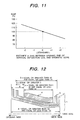
- Fig. 11 shows a relationship between the distance e being defined between the opening side end of the magnetic core 4 and the opening side end of the vertical deflection coil 3, and the change rate of the ELMF generating from the deflection yoke 1.
- the longer the ELMF the lower i.e., in the other words, it is possible to reduce the value of the ELMF by positioning the magnetic core 4 at a position being as far as possible from the opening side end of the vertical deflection coil. Accordingly, although the positional relationship of the parts constructing the deflection yoke 1 is shown in Fig.
- the sizes and the disposition of the deflection yoke 1 for use in the cathode ray tube which has the neck portion being equal or greater than ⁇ 24 mm and equal or less than ⁇ 25 mm in diameter thereof and has the deflection angle being equal or greater than 97° and equal or less than 105°, i.e., the size a of the horizontal deflection coil, the size b of the vertical deflection coil, and the size c of the magnetic core are to be equal or greater than 80 mm and equal or less than 100 mm, equal or greater than 50 mm and equal or less than 70 mm, and equal or greater than 30 mm and equal or less than 50 mm, respectively, further more preferably to be equal or greater than 90 mm and equal or less than 95 mm, equal or greater than 60 mm and equal or less than 65 mm, and equal or greater than 40 mm and equal or less than 45 mm, respectively, wherein the opening side end of the magnetic core 4 is separated from the opening side end of the vertical
- the neck portion being equal or greater than ⁇ 24 mm and equal or less than ⁇ 25 mm in diameter thereof and has the deflection angle being equal or greater than 97° and equal or less than 105°
- the neck diameter is equal or greater than ⁇ 18 mm and equal or less than ⁇ 26 mm, more preferably to be equal or greater than ⁇ 22 mm and equal or less than 26 mm and the deflection angle is equal or greater than 90° and equal or less than 115°, more preferably to be equal or greater than 95° and equal or less than 110°.
- the present embodiment is a cathode ray tube apparatus equipped with the deflection yoke mentioned above, and a side view thereof is shown in Fig. 13, in which a portion is shown by cutting thereof.
- the cathode ray tube apparatus of the present embodiment comprises the deflection yoke 1, the horizontal deflection coil 2, the vertical deflection coil 3, the magnetic core 4, the separator 5 for insulation, a magnetic body 6 for auxiliary vertical coil, an auxiliary vertical coil 7, a terminal cover 8, the electron gun 9, a static convergence magnet 10 and the phosphor screen 12.
- the deflection yoke 1 On the neck portion of the cathode ray tube 11 having the phosphor screen 12 in front thereof is attached the deflection yoke 1, and also in the neck portion of the cathode ray tube 11 is attached the electron guns.
- This deflection yoke 1 has construction in which there are positioned the horizontal deflection coil 2 and the vertical deflection coil 3, and the magnetic core 4 made of magnetic body on the outer periphery thereof. And, at side of the electron gun 9 is provided the magnetic body 6 for auxiliary vertical coil, on which the auxiliary vertical coil 7 is wound around.
- the cathode ray tube 11 used in this cathode ray tube apparatus has a large or wide deflection angle, therefore, in the case where the conventional deflection yoke is attached thereon, it is impossible to achieve the object without great changes in total parts thereof, including the driver circuit of the deflection yoke.
- the deflection yoke 1 of the present invention it is possible not only to suppress the generation the geometric distortion and the misconvergence, but also to obtain the cathode ray tube apparatus having such the wide deflection angle characteristic satisfying the standardized value of the useless magnetic filed emission (i.e., the LVMF and ELMF), without such the changes of the total parts except for the deflection yoke 1, and without deterioration in the horizontal and the vertical deflection sensitivities being important characteristics of the cathode ray tube.
- the LVMF and ELMF useless magnetic filed emission
- the present embodiment is a display device equipped with the cathode ray tube having the deflection yoke 1 mentioned above, and the constructive view thereof is shown in Fig. 14.
- Fig. 14 there are an input terminal 14 of video signal, an input terminal 15 of horizontal synchronization signal, an input terminal 16 of vertical synchronization signal, a video circuit 17, a horizontal deflection circuit 18, a vertical deflection circuit 19, and a high voltage circuit 20, wherein the portions corresponding to those shown in Fig. 13 are attached with the same numerical references so as to omit the duplicated explanation thereof.
- the video signal inputted from the video input terminal 14, after being treated with signal processing in the video circuit 17, is supplied to the cathode ray tube 11.
- the horizontal synchronization signal inputted from the input terminal 15 is supplied to the horizontal deflection circuit 18, wherein horizontal deflection current Ih is formed on the basis of the horizontal synchronization signal.
- This horizontal deflection current Ih is supplied to the horizontal deflection coil 2 of the deflection yoke 1.
- a portion of the horizontal synchronization signal mentioned above is also supplied to the high voltage circuit 20 at the same time.
- the vertical synchronization signal inputted to the input terminal 16 is supplied to the vertical deflection circuit 19, wherein vertical deflection current Iv is formed.
- this vertical deflection current Iv is supplied to the vertical deflection coil 3 of the deflection yoke 1.
- the electron beams emitted from the electron gun on the basis of the signals being processed in the video circuit 17 are deflected by the magnetic fields formed by the horizontal deflection current Ih and vertical deflection current Iv and excite luminescent materials located at predetermined positions on the phosphor screen 12.
- the cathode ray tube equipped with the deflection yoke 1 mentioned above it is possible to achieve the display device showing the wide deflection angle characteristics so as to satisfy the standardized value of the useless magnetic filed emission (i.e., the LVMF and ELMF), without changing the total constituent parts thereof except for the deflection yoke, such as the horizontal deflection circuit 18, the vertical deflection circuit 19 and the video circuit 17, etc., with using the conventional parts as they are, with no deterioration in the horizontal and the vertical deflection sensitivities but suppressing the generation of the geometric distortion and the misconvergence.
- the deflection yoke such as the horizontal deflection circuit 18, the vertical deflection circuit 19 and the video circuit 17, etc.
- the present invention there can be obtained effects that the useless magnetic filed emission can be decreased without using the canceling coil therein, and the sensitivities of the horizontal deflection coil and the vertical deflection coil come to be high, thereby contributing to supression of the geometric distortion and the misconvergence. Furthermore, it enables not only to make the deflection yoke itself small in size and light in weight, but also it is very effective to the reduction in manufacturing cost of the deflection yoke.
Abstract
Description
- The present invention relates to a deflection yoke being suitable for use in a thin necked cathode ray tube having a characteristic of a large or wide deflection angle and a cathode ray tube apparatus using thereof and a display device, in particular to a countermeasure against leakage magnetic field due to useless magnetic filed emission from the deflection yoke thereof.
- There rises a requirement that the useless magnetic filed emission generating in periphery of cathode ray tube apparatus must be reduced to be less than a certain value. In particular, with the useless magnetic filed emission in a low frequency band of less than 400 kHz, there already exists a guideline, being called TCO (The Swedish Confederation Employees, hereinafter be abbreviated by TCO) for example. This guideline determines that ELMF (Extremely Low Frequency Magnetic Field) from 5Hz to 2kHz should be equal or lower than 200 nT and VLMF (Very Low Frequency Magnetic Field) from 2kHz to 400 kHz be equal or lower than 25 nT, measuring at points in periphery of 50 cm from the display device and at distance of 30 cm from the tube surface of the cathode ray tube apparatus.
- Because main source of generating the ELMF and the VLMF is the deflection yoke, various means are proposed to generate magnetic field in a reverse polarity so as to cancel the useless magnetic filed emission, thereby achieving reduction of the useless magnetic filed emission being equal or lower than the value standardized therefor. As one representative example of them, a reducing device for the useless magnetic filed emission is described in Japanese Patent Laying-Open No. Hei 3-289029 (1991). In this device, cancellation coils are connected to a horizontal deflection coil and a vertical deflection coil, respectively, wherein magnetic filed is newly generated for the purpose of canceling the useless magnetic filed emission generated from the respective horizontal and vertical deflection coils, thereby reducing the useless magnetic filed emission.
- Also, in Japanese Patent Laying-Open No. Hei 3-165427 (1991) is disclosed a method for reducing the useless magnetic filed emission by devising or managing the sizes of the coils of the deflection yoke without using such the cancellation coils.
- However, according to the conventional technology shown in Japanese Patent Laying-Open No. Hei 3-289029 (1991), important characteristics of the deflection yoke are extremely deteriorated, such as the horizontal deflection sensitivity and the vertical deflection sensitivity, while decreasing the useless magnetic filed emission. Further, with connection of the cancellation coils, the deflection yoke increases in sizes of the outer shape and weight thereof, therefore, those not only bring about problems of rising up the production cost of deflection yokes, but also problems that they make destroy and manufacture of the cathode ray tube difficult exceeding a limit of mechanical strength at the neck portion of the cathode ray tube.
- On a while, according to the conventional technology shown in Japanese Patent Laying-Open No. Hei 3-165427 (1991), there is disclosed a worked-out plan that a magnet core is formed with the length in an axial direction thereof to be from 40% to 60% of the distance between front and behind of a bridging portion which constitutes the horizontal deflection coil, thereby suppressing the deterioration in characteristics of the deflection yoke.
- However, for a social needs desirous of appearing a cathode ray tube and/or a display apparatus having a wide display screen being thinner in the thickness thereof and a low electric energy consumption, however the conventional prior arts mentioned above pay no consideration onto the diameter of a neck portion of the cathode ray tube nor to shapes of the magnetic cores, which are needed for realizing the purpose of reduction in the useless magnetic filed emission while at the same time satisfying the basic deflection characteristics for the cathode ray tubes. Namely, cathode rays emitting from an electron gun reaches to a phosphor screen while being deflected by the magnetic field formed with the deflection yoke. In this instance, the magnetic field by the deflection yoke must be strengthened for enlarging the deflection angle, however this results to bring about not only the increase in electric energy consumption by the deflection yoke, but also increases in the shape and weight of the deflection yoke itself as well as in production cost thereof.
- For dissolving such problems of the conventional arts mentioned above, while it is possible to deflect the cathode rays at wide angle with a small magnetic field density by making thin the neck portion of the cathode ray tube where the deflection yoke is attached, on the other hand, the thinner the neck portion, the greater the decrease in the mechanical strength thereof, then it comes to be a big problem. Accordingly, it is desirout, of course, to lighten the weight of the magnetic core which occupies about 50% of the weight the deflection yoke being attached onto the neck portion, as well as to make designing of sizes of the deflection yoke for improving the characteristics so as to prevent from the deterioration thereof.
- According to the present invention, an object is, for dissolving such the problems, to provide a deflection yoke being applicable to a thin necked cathode ray tube showing a wide deflection angle characteristic, and a cathode ray tube using thereof, and a display device as well.
- For achieving the object mentioned above, according to the present invention, there is provided a deflection yoke to be attached to a cathode ray tube for use thereof, comprising:
- a horizontal coil;
- a vertical coil; and
- a magnetic core, wherein a ratio of thickness of said magnetic core in horizontal direction with respect to that in vertical direction is approximately equal to 1 or less than that, or preferably the ratio of thickness of said magnetic core includes approximately 1 and is equal or greater than 0.7, and said deflection yoke further comprising:
- an attachment portion for enabling to be attached to a neck of the cathode ray tube, which has diameter at least being equal or greater than 18 mm and being equal or less than 26 mm, preferably being equal or greater than 22 mm and being equal or less than 26 mm, the most preferably being equal or greater than 24 mm and being equal or less than 25 mm.
-
- And also, according to the present invention, there is provided the deflection yoke as defined in the above, wherein said cathode ray tube is over 90° and equal or less than 115° in deflection angle thereof, more preferably, is equal or greater than 95° and equal or less than 110° in the deflection angle thereof, and the most preferably, is equal or greater than 97° and equal or less than 105° in the deflection angle thereof.
- Also, according to the present invention, there is provided the deflection yoke as defined in the above, wherein sizes of said deflection yoke in an axial direction thereof are equal or greater than 80 mm and equal or less than 100 mm for said horizontal deflection coil thereof, or equal or greater than 50 mm and equal or less than 70 mm for said vertical deflection coil thereof, and equal or greater than 30 mm and equal or less than 50 mm for said magnetic core thereof.
- Further, preferably, the sizes of said deflection yoke in an axial direction thereof are equal or greater than 90 mm and equal or less than 95 mm for said horizontal deflection coil thereof, or equal or greater than 60 mm and equal or less than 65 mm for said vertical deflection coil thereof, and equal or greater than 40 mm and equal or less than 45 mm for said magnetic core thereof.
- Further, according to the present invention, there is also provided the deflection yoke as defined in the above, wherein said magnetic core is positioned so that distance between an opening side end of said horizontal deflection coil and that of said magnetic core is greater than distance between a neck side end of said horizontal deflection coil and a neck side end of said magnetic core, and in particular the distance is equal or greater than 15 mm.
- Furthermore, according to the present invention, there is also provided the deflection yoke as defined in the above, wherein said magnetic core is positioned so that distance between an opening side end of said vertical deflection coil and that of said magnetic core is greater than distance between a neck side end of said vertical deflection coil and a neck side end of said magnetic core, and in particular, the distance is equal or greater than 5 mm.
- And, according to the present invention, there is provided a cathode ray tube apparatus, comprising:
- a cathode ray tube;
- a deflection yoke; and
- an electron gun, wherein a neck of said cathode ray tube has diameter being equal or greater than 18 mm and equal or less than 26 mm, or more preferably equal or greater than 22 mm and equal or less than 26 mm, or most preferably equal or greater than 24 mm and equal or less than 25 mm, and deflection angle thereof is over 90° and equal or less than 115°, or more preferably equal or greater than 95° and equal or less than 110°, or most preferably equal or greater than 97° and equal or less than 105°, and wherein said deflection yoke comprises:
- a horizontal coil;
- a vertical coil; and
- a magnetic core, wherein a ratio of thickness of said magnetic core in horizontal direction with respect to that in vertical direction is approximately equal to 1 or less than that, or preferably the ratio of thickness of said magnetic core includes approximately 1 and is equal or greater than 0.7.
-
- And, according to the present invention, there is provided a display device having a cathode ray tube apparatus, in which a deflection yoke and an electron gun are attached onto a cathode ray tube, wherein:
- a neck of said cathode ray tube has diameter being equal or greater than 18 mm and equal or less than 26 mm and deflection angle thereof is over 90° and equal or less than 115°;
- said deflection yoke comprises:
- a horizontal coil;
- a vertical coil; and
- a magnetic core, wherein a ratio of thickness of said magnetic core in horizontal direction with respect to that in vertical direction is approximately equal to 1 or less than that, and said display device further comprising:
- a deflection circuit and a high voltage circuit for driving said cathode ray tube apparatus; and
- a video circuit for signal processing an external signal.
-
- In the drawings
- Those and other features, objects and advantages of the present invention will becomes more apparent from the following description when taken in conjunction with the accompanying drawings wherein:
- Fig. 1 is an explanatory view of showing a cross-section of a magnet core according to the present invention;
- Fig. 2 is an explanatory view of showing a cathode ray tube being attached on with the deflection yoke according to the present invention;
- Fig. 3 is a graph of showing a relationship between diameter of a neck portion of the cathode ray tube and resolution characteristic, and also electric energy consumption in the deflection yoke of an embodiment according to the present invention;
- Fig. 4 is an explanatory view of showing external shape and sizes of the deflection yoke of the embodiment according to the present invention, in particular, in a tube axis direction thereof;
- Fig. 5 is a graph for showing a relationship between the size and horizontal deflection sensitivity with a horizontal deflection coil of the embodiment according to the present invention;
- Fig. 6 is a graph for showing a relationship between the size and an amount of change in beam strike neck shadow in the horizontal deflection coil of the embodiment according to the present invention;
- Fig. 7 is a graph for showing a relationship between the external size of the horizontal deflection coil and a diameter of electron beams reaching upon a phosphor screen in the embodiment according to the present invention;
- Fig. 8 is a graph for showing a relationship between the external size of the horizontal deflection coil and allowable temperature in the embodiment according to the present invention;
- Fig. 9 is a graph for showing a relationship between distance, being defined between an opening side end of the horizontal deflection coil and an opening side end of a magnetic core, and strength of very low frequency magnetic field in an another embodiment according to the present invention;
- Fig. 10 is an explanatory view of showing an external shape and sizes of the deflection yoke of an other embodiment according to the present invention, in a tube axis direction thereof;
- Fig. 11 is a graph for showing a relationship between distance, being defined between an opening side end of a vertical deflection coil and an opening side end of the magnetic core, and strength of very low frequency magnetic field of the other embodiment according to the present invention;
- Fig. 12 is an explanatory view of showing an external shape and sizes of the deflection yoke of further other embodiment according to the present invention, in a tube axis direction thereof;
- Fig. 13 is a side view of a cathode ray tube apparatus equipped with the deflection yoke according to the present invention; and
- Fig. 14 is a constructive view of a display device equipped with the cathode ray tube having the deflection yoke according to the present invention.
-
- Hereinafter, embodiments according to the present invention will be fully explained by referring to the attached drawings.
- By referring to Fig. 1 showing the cross-section view of a
magnetic core 4 according to the present invention, adeflection yoke 1, being constructed with ahorizontal deflection coil 2 and avertical deflection coil 3, is attached to be used therein onto a cathode ray tube which has a neck portion of diameter from 18 mm to 26 mm and has a deflection angle from 90° to 115°. Here, the neck diameter is that being measured in a portion of the cathode ray tube where an electron gun (in collective) is attached, and where it shows almost equal value of diameter when being measure by well-known measurement devices, such as a vernier caliper, a micrometer, etc. Also, in general, the deflection angle is defined as an angle being formed between a diagonal effective display surface on the phosphor screen when seeing into the phosphor screen from a deflection center, e.g., a point where tapered portions of the cathode ray tube are concentrated at one point by extrapolation. - The
magnetic core 4 mentioned above has an inner surface being formed in a circular shape, and it is formed so that a ratio of core thickness is at least approximately equal to 1 or less than that in a vertical direction with respect to a horizontal direction, on which three electron guns of red (R), green (G) and blue (B) are disposed on a straight line. In a case where the magnetic core having the such cross-section is applied to the deflection yoke, the deflection magnetic field is formed by thehorizontal deflection coil 2 and thevertical deflection coil 3, being weak in the vertical direction but relatively strong in the horizontal direction comparing to that in the vertical direction, in the neck portion of the cathode ray tube where cathode rays from the electron guns run through. However, since the core thickness in the horizontal direction is sufficiently large, the magnetic field generated does not occur saturation with respect to coil current, therefore it is possible to maintain the magnetic field having sufficient strength thereof. Also, with this, not only geometric distortion and misconvergence, but also deterioration in the characteristics following increase of temperature in themagnetic core 4 can be compensated freely. - Also, in a case where the core thickness of the
magnetic core 4 is uniform, among the parts constructing thedeflection yoke 1, since it occupies about 50% of the weight in thedeflection coil 1, the cathode ray tube is easily broken down at the neck portion thereof. However, according to the present invention, the weight can be lightened by approximately 20% by making the core thickness of themagnetic core 4 thin in the vertical direction comparing to that in the horizontal direction, therefore it is possible not only to achieve the weight-lighting of thedeflection yoke 1 itself, but also to prevent from the breakage of the cathode ray tube at the neck portion thereof. - Here, the core ratio of the thickness of the
magnetic core 4 in the vertical direction with respect to that in the horizontal direction includes at least to be approximately 1, and it is preferably to be less than that and also equal to or greater than 0.7. The reason of this is that, themagnetic core 4 itself can obtain sufficient mechanical strength in manufacturing process thereof if the core ratio is equal to or greater than 0.7, therefore it can be manufactured by use of manufacturing methods being now widely used, such as a casting method, without decrease in productivity thereof. - Also, as shown in Fig. 2, the
deflection yoke 1 equipped with themagnetic core 4 mentioned above is fixed on awall surface 11 of the cathode ray tube by using anattachment portion 21. In this manner, the weight of thedeflection yoke 1 itself is supported by thewall surface 11 of the cathode ray tube as far as possible, then it is possible to avoid situation of the breakage at the neck portion. Further, thedeflection yoke 1 is also fixed onto the neck portion of the cathode ray tube by using afastening belt 22, however it is for preventing from movement of thedeflection yoke 1. - However, the deflection angle and the diameter of the neck portion of the cathode ray tube, on which the
deflection yoke 1 is attached to be used, should not be restricted only to such the regions as mentioned in the above. Namely, the deflection angle is preferable from 95° to 110°, and the most preferable within a region from 97° to 105°. The reason is that, when the deflection yoke is used, being same to that which is attached to the cathode ray tube having the deflection angle characteristic mentioned above, e.g., from 90° to 115°, the magnetic field necessary for deflecting at the desired angle can be minimized while maintaining the same deflection characteristics as mentioned in the above. Namely, reduction in electric energy consumption by thedeflection yoke 1 itself can be obtained, further a circuitry for driving thedeflection yoke 1 also can be achieved by circuit construction being simple comparing to that of the case mentioned above, or can be constructed with parts, such as, transistors of small capacities or the like, thereby contributing greatly to cost reduction of a control system as a whole including thedeflection yoke 1. - Furthermore, the diameter of neck of the cathode ray tube, on which the
deflection yoke 1 is attached, should not be restricted only to that value mentioned above, e.g., being equal or greater than 18 mm and equal or less than 26 mm. Preferably, it is desired that the diameter of the neck is equal or greater than 22 mm and equal or less than 26 mm, and moreover is equal or greater than 24 mm and equal or less than 25 mm. The reasons, when thesame deflection yoke 1 is attached onto the neck portion of the cathode ray tube to be used, can be explained from a relationship between the neck diameter and the resolution as one of performances of the cathode ray tube, and that between electric energy consumption of a deflection circuit including the deflection yoke, as shown in Fig. 3. In Fig. 3, the vertical axis indicates the resolution and the electric energy consumption by a relative value thereof, wherein the larger the neck diameter is, the easier the beam can be focused on the phosphor screen of the cathode ray tube, therefore display can be achieved with high resolution. On the contrary, the electric energy consumption of thedeflection yoke 1 itself rises up, therefore, there is a possibility not only the social needs desirous of low energy consumption by the deflection yoke cannot be met, but also it brings about decrease in the performances of the deflection yoke itself, at the worst, for example, when heat generation following the increase of energy consumption softens the parts constructing thedeflection yoke 1, such as a frame made of plastic resin. In particular, the electric energy consumption shows the relationship of increasing up abruptly when the neck diameter exceeds 26 mm. On a while, the neck being equal or less than 18 mm in diameter thereof brings about abrupt decrease of the resolution. - The neck diameter being equal or greater 18 mm and equal or less than 26 mm is a range necessary for satisfying at least both of the characteristics, e.g., the resolution and the energy consumption of the deflection yoke among the various performances of the cathode ray tube, in more preferable, it should be equal or greater 22 mm and equal or less than 26 mm, and in most preferable, be equal or greater 24 mm and equal or less than 25 mm, thereby enabling to meet with the social needs, in any one of the characteristics, including the resolution and the energy consumption.
- Next, sizes of various parts constructing the
deflection yoke 1 will be explained. Hereinafter, the deflection yoke will be explained by taking as a representative example, which is attached onto the cathode ray tube, having the neck diameter being equal or greater than 24 mm and equal or less than 25 mm and deflection angle being equal or greater than 97° and equal or less than 105°, to be used therein. - Fig. 4 shows the sizes in tube axis direction of the
deflection yoke 1 which is used for the cathode ray tube having the neck diameter being equal or greater than 24 mm and equal or less than 25 mm and deflection angle being equal or greater than 97° and equal or less than 105°. Thedeflection yoke 1 of the present embodiment, including ahorizontal deflection coil 2 and avertical deflection coil 3, as well as themagnetic core 4 shown in Fig. 1 mentioned above, wherein length in tube axis direction of thehorizontal deflection coil 2 is a, length in tube axial direction of thevertical deflection coil 3 is b, length in tube axis direction of themagnetic core 4 is c, distance between the opening side end of thehorizontal deflection coil 2 and the opening side end of thecore 4 is d, and distance between the opening side end of thevertical deflection coil 3 and the opening side end of thecore 4 is e. However, the sizes of thehorizontal deflection coil 2, thevertical deflection coil 3 and themagnetic core 4 are lengths measured between the opening side ends and the neck side ends of those coils and the core, respectively, by means of well-known measurement devices, such as a vernier caliper, a micrometer, etc. Further, thehorizontal deflection coil 2 and thevertical deflection coil 3 are coils, each of which is wound in a saddle-like shape. - Fig. 5 is a graph showing change rate of horizontal deflection sensitivity with respect to the length a in the tube axis direction of the
horizontal deflection coil 2. In the same Fig., on the basis that the size a of thehorizontal deflection coil 2 is 90 mm, there are shown cases where the length of thedeflection yoke 1 is changed or shifted into both the directions of the opening side and the neck side thereof, respectively. In a case where only the size a of the horizontal deflection coil is elongated or extended into the opening side, then the horizontal deflection sensitivity is increased up, while the deflection characteristic shows tendency to be deteriorated. On the other hand, in a case where only the size a of the horizontal deflection coil is elongated into the neck side, then the horizontal deflection sensitivity is decreased down, while the deflection characteristic is improved up. Namely, with the sizes of thedeflection yoke 1 to be attached onto a cathode ray tube having the wide deflection angle, it can be said that, it is effective that the length of the horizontal deflection coil is elongated into the neck side from the present position but it is shrunk in the opening side end for the purpose of improvement in the horizontal deflection sensitivity. - Next, Fig. 6 is a graph showing change amount of beam strike neck (hereinafter, being abbreviated as "BSN") of electron beams with respect to the length a in the tube axis direction of the
horizontal deflection coil 2. In the same Fig., the BSN change rate indicates cases where the size a of thehorizontal deflection coil 2 is changed or shifted into the direction of the opening side of thedeflection yoke 1 and the neck side, respectively, on the basis that the size thereof is 90 mm, and it means that the larger the value is, the less the ratio of lacking display screen appearing on the phosphor screen of the cathode ray tube. In a case where the size a of thehorizontal deflection coil 2 is enlarged into the opening side, the value of BSN is increased up, namely the performances of the cathode ray tube is improved. On the other hand, in a case where the size a of thehorizontal deflection coil 2 is extended into the neck side, the value of BSN is decreased down, therefore the lacks of the display screen easily appears on the phosphor screen of the cathode ray tube. Accordingly, it can be said, in order to improve the BSN value, it is effective to extend the size a of thehorizontal deflection coil 2 not into the direction of the neck side but into the direction of the opening side from the standard position. - However, from those results of Figs. 5 and 6, the relationship between the horizontal deflection sensitivity indicating the performances of the
deflection yoke 1 and the BSN is a reversed one with respect to the size of thehorizontal deflection coil 2. For satisfying both deflection characteristics, when changing the size a of thehorizontal deflection coil 2, it is indispensable to change it into both directions of the opening side of thedeflection yoke 1 and the neck side at the same time. However, for determining the size a of thehorizontal deflection coil 2 while satisfying the various characteristics of thedeflection yoke 1, there exists an appropriate range of sizes for the size a of the horizontal deflection coil, as will be explained below. - Then, first of all, explanation will be given on an upper limit of the size a of the
horizontal deflection coil 2 in the tube axis direction thereof. Fig. 7 shows a relationship between the size a of thehorizontal deflection coil 2 and a beam diameter of the electron beams on the phosphor screen of the cathode ray tube. In the same Fig., the size of beam diameter is indicated by 100% where no focus deterioration occurs, such as mis-focusing of images on the display screen. As a result of this, the size a of thehorizontal deflection coil 2 hardly gives influence upon the beam diameter if it is changed into the opening side of thedeflection yoke 1, however, in particular when the size a is increased in the direction of the neck side, the beam diameter rises up remarkably, thereby generating a problem, e.g., the focus deterioration of images. Namely, the maximum value of size a of thehorizontal deflection coil 2 is determined by an allowable focus characteristic at the neck side while by the horizontal deflection characteristic at the opening side thereof. Accordingly, from the result shown in the same Fig., it is apparent that the maximum allowable value in the size of thehorizontal deflection coil 2 is 100 mm for satisfying one of performances of the cathode ray tube, e.g., sharpness of image or the resolution, and further the characteristic of the deflection sensitivity. - Next, explanation will be given on a lower limit of the size a of the
horizontal deflection coil 2 in the tube axis direction thereof. Another method for determining the size a of thehorizontal deflection coil 2 while maintaining the deflection sensitivity is to shorten the size a at both the opening side and the neck side of thedeflection yoke 1 at the same time. In this instance, thehorizontal deflection coil 2 inevitably becomes small in shape thereof, therefore surface of the deflection coil itself also becomes small or narrow, and as the result of this, the increase in temperature of the deflection coil itself comes to be remarkable. Fig. 8 shows a relationship between the size a and the increase of temperature in the deflection yoke. In the same Fig., the temperature is indicated on the basis of the maximum allowable temperature of thedeflection yoke 1, and it is determined by the following reasons. Namely, in general, plastic mold material is used for forming the frame of thedeflection yoke 1, but it is remarkably decreased down in mechanical strength by itself when the temperature exceeds the thermal softening temperature thereof, therefore it is impossible to maintain the shape of the frame itself. Also conductors themselves of the deflection coil are covered by plastic resin (such as, enamel) for forming them fixed together, however, when the temperature exceeds the heat-resisting deform temperature thereof, not only that it is difficult for the conductors of the coil themselves to maintain the shapes thereof, but also that the enamel layer covering over the conductor is decreased down in the electric insulation thereof, thereby generating corona discharges locally therein. In the case of falling in such the situation, the deflection yoke looses the function thereof and brings about generation of the misconvergence. - Accordingly, it is inevitable for the size a of the horizontal deflection coil constructing the
deflection yoke 1 to be selected within a range so that it does not exceed the maximum allowable temperature of the parts material used therein. From the result shown in Fig. 8, it is apparent that the size a of thehorizontal deflection coil 2 must be equal or greater than 80 mm so as to satisfy the allowable value with respect to the increase of temperature in thedeflection yoke 1. - From the results in the above, when the size a of the
horizontal deflection coil 2 is set to be equal or greater than 80 mm and equal or less than 100 mm, it can show good deflection characteristics with respect to the cathode ray tube of thin neck type having characteristic of wide deflection angle, without occurring deterioration in focusing of images, and it is also possible to prevent from occurrence of the misconvergence following such the increase of temperature. - Next, explanation will be given on the size b in the tube axis direction of the
vertical deflection coil 3, being one of the parts constructing thedeflection yoke 1. - As is shown in Fig. 4, the size b in the tube axis direction of the
vertical deflection coil 3 is equal to the size being obtained by subtracting the thickness of fringes at the opening side and the neck side of thehorizontal deflection coil 2 as well as the thickness of a separator (not shown in Fig.) for insulating both thehorizontal deflection coil 2 and thevertical deflection coil 3 from the size a of thehorizontal deflection coil 2. For example, in the case that the thickness of the fringes at the opening side and the neck side of thehorizontal deflection coil 2 are approximately 5 mm and approximately 20 mm, respectively, and that each thickness at the opening side and the neck side of the separator for insulation is approximately 2 mm, then the size b of thevertical deflection coil 3 comes to be length being shorter than the size a of thehorizontal deflection coil 2 by the length approximately 30 mm. Accordingly, when the size a of thehorizontal deflection coil 2 is determined to be equal or greater than 80 mm and equal or less than 100 mm, it is preferable for the size b of the vertical deflection coil to be within a range, being equal or greater than 50 mm and equal or less than 70 mm. - In the same manner, the size c in the tube axis direction of the
magnetic core 4 is equal to the size being obtained by subtracting the thickness of fringes at the opening side and the neck side in thevertical deflection coil 3 as well as the thickness of spaces for insulating from the size b of thevertical deflection coil 3. For example, in the case that the thickness of the fringes at the opening side and the neck side of thevertical deflection coil 3 are approximately from 5 mm to 8 mm, in general, and by taking the spaces for insulation between thevertical deflection coil 3 and themagnetic core 4, i.e., approximately 4 mm, into the consideration, it is preferable for the size c in the tube direction of themagnetic core 4 to be shorter than the size b of thevertical deflection coil 3 by approximately 20 mm, i.e., within a range being equal or greater than approximately 30 mm and equal or less than approximately 50 mm. - As is mentioned in the above, the sizes of the
horizontal deflection coil 2, thevertical deflection coil 3 and themagnetic coil 4 are selected to be equal or greater than 80 mm and equal or less than 100, equal or greater than 50 mm and equal or less than 70, and equal or greater than 30 mm and equal or less than 50, respectively, and they are used as thedeflection yoke 1 for use of the thin neck type cathode ray tube having the wide deflection characteristic, thereby enabling deflection of the electron beam emitted from the electron guns with suppressing the occurrence of the geometric distortion of vertical direction and the misconvergence, i.e., without bringing about the deterioration of the horizontal deflection sensitivity and the vertical deflection sensitivity. - However, the respective sizes of the
horizontal deflection coil 2, thevertical deflection coil 3 and themagnetic core 4 should not be restricted only to those mentioned in the above, and they are preferably selected to be equal or greater than 90 mm and equal or less than 95 mm, equal or greater than 60 mm and equal or less than 65 mm, and equal or greater than 40 mm and equal or less than 45 mm, respectively. The reason is, since the upper limit of each size is restricted by the resolution and the characteristic of sensitivities, which are a part of the performances of the cathode ray tube, it is possible to increase up margin with respect to the characteristics of the cathode ray tube by determining those sizes to be shorter than those sizes mentioned above. This contributes, not only to thedeflection yoke 1 itself, but also to the increase in yield rate and productivity of the cathode ray tube being attached with thisdeflection yoke 1, greatly, and furthermore to the reduction of manufacturing cost thereof. On the other hand, the lower limit of each size is determined on the allowable value with respect to increase of temperature of thedeflection yoke 1, therefore, by selecting those sizes to be longer than the above-mentioned sizes, it is possible to suppress the increase of temperature of thedeflection yoke 1, i.e., to obtain reduction of the electric energy consumption. With this, it is possible to make circuitry for driving thedeflection yoke 1 simple comparing to thedeflection yoke 1 of the above-mentioned sizes, or to make the parts used therein, such as the capacities of transistors or the like, small, and at the end to contribute to the cost reduction. - Next, as is shown in Fig. 4, when assembling the
horizontal deflection coil 2, thevertical deflection coil 3 and themagnetic core 4, which construct thedeflection yoke 1, following devices must be made in a relationship of the relative positions of each of those parts. Namely, each one of the distances, i.e., the distance d between the opening side end of themagnetic core 4 and the opening side end of thehorizontal deflection coil 2 and the distance d between the opening side end of themagnetic core 4 and the opening side end of thevertical deflection coil 3, is determined to be at least larger than the distance at the neck side, and to be large as far as possible, and for thehorizontal deflection coil 2, thevertical deflection coil 3 and themagnetic core 4, it is necessary to be attached onto the neck portion of the cathode ray tube with keeping such the positional relationships thereof. - Fig. 9 shows a graph for explaining an another embodiment of the
deflection yoke 1 according to the present invention. In the same Fig., there is shown a relationship between the distance d defined between the opening side end of themagnetic core 4 and the opening side end of thehorizontal deflection coil 2, and the change rate of the VLMF generating from thedeflection yoke 1. As is apparent from this result, the longer the distance d, the lower the value of the VLMF, namely, in other words, it is possible to reduce the VLMF by positioning themagnetic core 4 as far as possible from the phosphor screen of the cathode ray tube. Accordingly, though showing the positional relationships of the parts constructing thedeflection yoke 1 in Fig. 10, in order to satisfy the standardized value (being equal or less than 25 nT) for the VLMF, it is necessary to determine the distance d between the opening side end of themagnetic core 4 and the opening side end of thehorizontal deflection coil 2 to be equal or greater than 15 mm. - As was mentioned previously, the sizes and the disposition of the deflection yoke 1 for use in the cathode ray tube, which has the neck portion being equal or greater than 24 mm and equal or less than 25 mm in diameter thereof and has the deflection angle being equal or greater than 97° and equal or less than 105°, i.e., the size a of the horizontal deflection coil, the size b of the vertical deflection coil, and the size c of the magnetic core are to be equal or greater than 80 mm and equal or less than 100 mm, equal or greater than 50 mm and equal or less than 70 mm, and equal or greater than 30 mm and equal or less than 50 mm, respectively, further more preferably to be equal or greater than 90 mm and equal or less than 95 mm, equal or greater than 60 mm and equal or less than 65 mm, and equal or greater than 40 mm and equal or less than 45 mm, respectively, wherein the opening side end of the magnetic core 4 is separated from the opening side end of the horizontal deflection coil by a distance being equal or greater than 15 mm, thereby obtaining the inherent characteristics of the deflection yoke 1 without using the canceling coils being widely used in conventional art, and enabling to reduce the VLMF caused by the deflection yoke 1 while suppressing the generation of the geometric distortion and the misconvergence.
- Next, explanation will be given on an other embodiment of the present invention. Fig. 11 shows a relationship between the distance e being defined between the opening side end of the
magnetic core 4 and the opening side end of thevertical deflection coil 3, and the change rate of the ELMF generating from thedeflection yoke 1. As the result of this, the longer the ELMF the lower, i.e., in the other words, it is possible to reduce the value of the ELMF by positioning themagnetic core 4 at a position being as far as possible from the opening side end of the vertical deflection coil. Accordingly, although the positional relationship of the parts constructing thedeflection yoke 1 is shown in Fig. 12, however, in order to satisfy the standardized value (equal or less than 200 nT) of the ELMF, it is necessary to determine the distance e defined between the opening side end of themagnetic core 4 and the opening side end of thevertical deflection coil 3 to be equal or greater than 5 mm. - As was mentioned previously, the sizes and the disposition of the deflection yoke 1 for use in the cathode ray tube, which has the neck portion being equal or greater than 24 mm and equal or less than 25 mm in diameter thereof and has the deflection angle being equal or greater than 97° and equal or less than 105°, i.e., the size a of the horizontal deflection coil, the size b of the vertical deflection coil, and the size c of the magnetic core are to be equal or greater than 80 mm and equal or less than 100 mm, equal or greater than 50 mm and equal or less than 70 mm, and equal or greater than 30 mm and equal or less than 50 mm, respectively, further more preferably to be equal or greater than 90 mm and equal or less than 95 mm, equal or greater than 60 mm and equal or less than 65 mm, and equal or greater than 40 mm and equal or less than 45 mm, respectively, wherein the opening side end of the magnetic core 4 is separated from the opening side end of the vertical deflection coil by the distance being equal or greater than 5 mm, thereby obtaining the inherent characteristics of the deflection yoke 1 without using the canceling coils being widely used in conventional art, and enabling to reduce the ELMF caused by the deflection yoke 1 while suppressing the generation of the geometric distortion and the misconvergence.
- As was mentioned in the above, by attaching it onto the neck portion of the cathode ray tube while positioning so as to make the distance d of the opening side end of the
horizontal deflection coil 2 with respect to the opening side end of themagnetic core 4 and the distance e with respect to the opening side end of thevertical deflection coil 3 as large as possible, it is possible not only to reduce the useless magnetic filed emission (i.e., the LVMF and ELMF) generating from thedeflection yoke 1 without using the canceling coils being widely used in conventional art, but also to suppress occurrences of deterioration of the horizontal deflection sensitivity and the vertical deflection sensitivity, the geometric distortion, and the misconvergence. Furthermore, it is possible to contribute to minimization in shape of the deflection yoke and weight lightening thereof, as well as cutback in manufacturing cost thereof. - In the above, though there are mentioned the sizes and the disposition of the
deflection yoke 1 for use in the cathode ray tube, for example, which has the neck portion being equal or greater than 24 mm and equal or less than 25 mm in diameter thereof and has the deflection angle being equal or greater than 97° and equal or less than 105°, as one representative example, but, needless to say, it may be easily assumed that those results also could be obtained if the neck diameter is equal or greater than 18 mm and equal or less than 26 mm, more preferably to be equal or greater than 22 mm and equal or less than 26 mm and the deflection angle is equal or greater than 90° and equal or less than 115°, more preferably to be equal or greater than 95° and equal or less than 110°. - Next, explanation will be given on a further other embodiment according to the present invention. The present embodiment is a cathode ray tube apparatus equipped with the deflection yoke mentioned above, and a side view thereof is shown in Fig. 13, in which a portion is shown by cutting thereof. And, the cathode ray tube apparatus of the present embodiment comprises the
deflection yoke 1, thehorizontal deflection coil 2, thevertical deflection coil 3, themagnetic core 4, theseparator 5 for insulation, amagnetic body 6 for auxiliary vertical coil, an auxiliaryvertical coil 7, aterminal cover 8, the electron gun 9, astatic convergence magnet 10 and thephosphor screen 12. - In the same Fig., on the neck portion of the
cathode ray tube 11 having thephosphor screen 12 in front thereof is attached thedeflection yoke 1, and also in the neck portion of thecathode ray tube 11 is attached the electron guns. Thisdeflection yoke 1 has construction in which there are positioned thehorizontal deflection coil 2 and thevertical deflection coil 3, and themagnetic core 4 made of magnetic body on the outer periphery thereof. And, at side of the electron gun 9 is provided themagnetic body 6 for auxiliary vertical coil, on which the auxiliaryvertical coil 7 is wound around. - The
cathode ray tube 11 used in this cathode ray tube apparatus has a large or wide deflection angle, therefore, in the case where the conventional deflection yoke is attached thereon, it is impossible to achieve the object without great changes in total parts thereof, including the driver circuit of the deflection yoke. However, by applying the above-mentioneddeflection yoke 1 of the present invention into, it is possible not only to suppress the generation the geometric distortion and the misconvergence, but also to obtain the cathode ray tube apparatus having such the wide deflection angle characteristic satisfying the standardized value of the useless magnetic filed emission (i.e., the LVMF and ELMF), without such the changes of the total parts except for thedeflection yoke 1, and without deterioration in the horizontal and the vertical deflection sensitivities being important characteristics of the cathode ray tube. - Next, explanation will be on a further other embodiment according to the present invention. The present embodiment is a display device equipped with the cathode ray tube having the
deflection yoke 1 mentioned above, and the constructive view thereof is shown in Fig. 14. In the same Fig., there are aninput terminal 14 of video signal, aninput terminal 15 of horizontal synchronization signal, aninput terminal 16 of vertical synchronization signal, avideo circuit 17, ahorizontal deflection circuit 18, avertical deflection circuit 19, and ahigh voltage circuit 20, wherein the portions corresponding to those shown in Fig. 13 are attached with the same numerical references so as to omit the duplicated explanation thereof. - The video signal inputted from the
video input terminal 14, after being treated with signal processing in thevideo circuit 17, is supplied to thecathode ray tube 11. Also, the horizontal synchronization signal inputted from theinput terminal 15 is supplied to thehorizontal deflection circuit 18, wherein horizontal deflection current Ih is formed on the basis of the horizontal synchronization signal. This horizontal deflection current Ih is supplied to thehorizontal deflection coil 2 of thedeflection yoke 1. On the other hand, a portion of the horizontal synchronization signal mentioned above is also supplied to thehigh voltage circuit 20 at the same time. Also, the vertical synchronization signal inputted to theinput terminal 16 is supplied to thevertical deflection circuit 19, wherein vertical deflection current Iv is formed. And, this vertical deflection current Iv is supplied to thevertical deflection coil 3 of thedeflection yoke 1. In this manner, the electron beams emitted from the electron gun on the basis of the signals being processed in thevideo circuit 17 are deflected by the magnetic fields formed by the horizontal deflection current Ih and vertical deflection current Iv and excite luminescent materials located at predetermined positions on thephosphor screen 12. By applying the cathode ray tube equipped with thedeflection yoke 1 mentioned above to this display device, it is possible to achieve the display device showing the wide deflection angle characteristics so as to satisfy the standardized value of the useless magnetic filed emission (i.e., the LVMF and ELMF), without changing the total constituent parts thereof except for the deflection yoke, such as thehorizontal deflection circuit 18, thevertical deflection circuit 19 and thevideo circuit 17, etc., with using the conventional parts as they are, with no deterioration in the horizontal and the vertical deflection sensitivities but suppressing the generation of the geometric distortion and the misconvergence. - As was fully mentioned in the above, according to the present invention, there can be obtained effects that the useless magnetic filed emission can be decreased without using the canceling coil therein, and the sensitivities of the horizontal deflection coil and the vertical deflection coil come to be high, thereby contributing to supression of the geometric distortion and the misconvergence. Furthermore, it enables not only to make the deflection yoke itself small in size and light in weight, but also it is very effective to the reduction in manufacturing cost of the deflection yoke.
- While we have shown and described several embodiments in accordance with our invention, it should be understood that disclosed embodiments are susceptible of changes and modifications without departing from the scope of the invention. Therefore, we do not intend to be bound by the details shown and described herein but intend to cover all such changes and modifications falling within the ambit of the appended claims.
Claims (34)
- A deflection yoke being attached to a cathode ray tube for use therein, comprising:a horizontal coil;a vertical coil; anda magnetic core, wherein a ratio of thickness of said magnetic core in horizontal direction with respect to that in vertical direction is approximately equal to 1 or less than that, and said deflection yoke further comprising:an attachment portion for enabling to be attached to a neck of the cathode ray tube, which has diameter being equal or greater than 18 mm and being equal or less than 26 mm.
- A deflection yoke as defined in the claim 1, wherein said cathode ray tube is over 90° and equal or less than 115° in deflection angle thereof.
- A deflection yoke as defined in the claim 2, wherein said cathode ray tube is equal or greater than 95° and equal or less than 110° in the deflection angle thereof.
- A deflection yoke as defined in the claim 2, wherein said cathode ray tube is equal or greater than 97° and equal or less than 105° in the deflection angle thereof.
- A deflection yoke as defined in the claim 1, wherein the neck of said cathode ray tube has diameter being equal or greater than 22 mm and equal or less than 26 mm.
- A deflection yoke as defined in the claim 3, wherein the neck of said cathode ray tube has diameter being equal or greater than 22 mm and equal or less than 26 mm.
- A deflection yoke as defined in the claim 4, wherein the neck of said cathode ray tube has diameter being equal or greater than 22 mm and equal or less than 26 mm.
- A deflection yoke as defined in the claim 1, wherein the neck of said cathode ray tube has diameter being equal or greater than 24 mm and equal or less than 25 mm.
- A deflection yoke as defined in the claim 3, wherein the neck of said cathode ray tube has diameter being equal or greater than 24 mm and equal or less than 25 mm.
- A deflection yoke as defined in the claim 4, wherein the neck of said cathode ray tube has diameter being equal or greater than 24 mm and equal or less than 25 mm.
- A deflection yoke as defined in the claim 1, wherein the ratio of the thickness of said magnetic core in horizontal direction with respect to that in the vertical direction is approximately equal to 1 or less than that, and is equal or greater than 0.7.
- A deflection yoke as defined in the claim 1, wherein sizes of said deflection yoke in an axial direction thereof are equal or greater than 80 mm and equal or less than 100 mm for said horizontal deflection coil thereof, equal or greater than 50 mm and equal or less than 70 mm for said vertical deflection coil thereof, and equal or greater than 30 mm and equal or less than 50 mm for said magnetic core thereof.
- A deflection yoke as defined in the claim 1, wherein sizes of said deflection yoke in an axial direction thereof are equal or greater than 90 mm and equal or less than 95 mm for said horizontal deflection coil thereof, equal or greater than 60 mm and equal or less than 65 mm for said vertical deflection coil thereof, and equal or greater than 40 mm and equal or less than 45 mm for said magnetic core thereof.
- A deflection yoke as defined in the claim 1, wherein said magnetic core is positioned so that distance between an opening side end of said horizontal deflection coil and that of said magnetic core is greater than distance between a neck side end of said horizontal deflection coil and a neck side end of said magnetic core.
- A deflection yoke as defined in the claim 1, wherein distance between an opening side end of said horizontal deflection coil and that of said magnetic core is equal or greater than 15 mm.
- A deflection yoke as defined in the claim 1, wherein said magnetic core is positioned so that distance between an opening side end of said vertical deflection coil and that of said magnetic core is greater than distance between a neck side end of said vertical deflection coil and a neck side end of said magnetic core.
- A deflection yoke as defined in the claim 1, wherein distance between an opening side end of said vertical deflection coil and that of said magnetic core is equal or greater than 5 mm.
- A cathode ray tube apparatus, comprising:a cathode ray tube;a deflection yoke; andan electron gun, wherein a neck of said cathode ray tube has diameter being equal or greater than 18 mm and equal or less than 26 mm and deflection angle thereof is over 90° and equal or less than 115°, and wherein said deflection yoke comprises:a horizontal coil;a vertical coil; anda magnetic core, wherein a ratio of thickness of said magnetic core in horizontal direction with respect to that in vertical direction is approximately equal to 1 or less than that.
- A cathode ray tube as defined in the claim 18, wherein said cathode ray tube is equal or greater than 95° and equal or less than 110° in deflection angle thereof.
- A cathode ray tube as defined in the claim 18, wherein said cathode ray tube is equal or greater than 97° and equal or less than 105° in deflection angle thereof.
- A cathode ray tube as defined in the claim 18, wherein a neck of the cathode ray tube has diameter being equal or greater than 22 mm and being equal or less than 26 mm.
- A cathode ray tube as defined in the claim 19, wherein a neck of the cathode ray tube has diameter being equal or greater than 22 mm and being equal or less than 26 mm.
- A cathode ray tube as defined in the claim 20, wherein a neck of the cathode ray tube has diameter being equal or greater than 22 mm and being equal or less than 26 mm.
- A cathode ray tube as defined in the claim 18, wherein a neck of the cathode ray tube has diameter being equal or greater than 24 mm and being equal or less than 25 mm.
- A cathode ray tube as defined in the claim 19, wherein a neck of the cathode ray tube has diameter being equal or greater than 24 mm and being equal or less than 25 mm.
- A cathode ray tube as defined in the claim 20, wherein a neck of the cathode ray tube has diameter being equal or greater than 24 mm and being equal or less than 25 mm.
- A cathode ray tube as defined in the claim 18, wherein the ratio of the thickness of said magnetic core in horizontal direction with respect to that in the vertical direction is approximately equal to 1 or less than that, and is equal or greater than 0.7.
- A cathode ray tube as defined in the claim 18, wherein sizes of said deflection yoke in an axial direction thereof are equal or greater than 80 mm and equal or less than 100 mm for said horizontal deflection coil thereof, equal or greater than 50 mm and equal or less than 70 mm for said vertical deflection coil thereof, and equal or greater than 30 mm and equal or less than 50 mm for said magnetic core thereof.
- A cathode ray tube as defined in the claim 18, wherein sizes of said deflection yoke in an axial direction thereof are equal or greater than 90 mm and equal or less than 95 mm for said horizontal deflection coil thereof, equal or greater than 60 mm and equal or less than 65 mm for said vertical deflection coil thereof, and equal or greater than 40 mm and equal or less than 45 mm for said magnetic core thereof.
- A cathode ray tube as defined in the claim 18, wherein said magnetic core is positioned so that distance between an opening side end of said horizontal deflection coil and that of said magnetic core is greater than distance between a neck side end of said horizontal deflection coil and a neck side end of said magnetic core.
- A cathode ray tube as defined in the claim 18, wherein distance between an opening side end of said horizontal deflection coil and that of said magnetic core is equal or greater than 15 mm.
- A cathode ray tube as defined in the claim 18, wherein said magnetic core is positioned so that distance between an opening side end of said vertical deflection coil and that of said magnetic core is greater than distance between a neck side end of said vertical deflection coil and a neck side end of said magnetic core.
- A cathode ray tube as defined in the claim 18, wherein distance between an opening side end of said vertical deflection coil and that of said magnetic core is equal or greater than 5 mm.
- A display device having a cathode ray tube apparatus, in which a deflection yoke and an electron gun are attached onto a cathode ray tube, wherein:a neck of said cathode ray tube has diameter being equal or greater than 18 mm and equal or less than 26 mm and deflection angle thereof is over 90° and equal or less than 115°;said deflection yoke comprises:a horizontal coil;a vertical coil; anda magnetic core, wherein a ratio of thickness of said magnetic core in horizontal direction with respect to that in vertical direction is approximately equal to 1 or less than that, and said display device further comprising:a deflection circuit and a high voltage circuit for driving said cathode ray tube apparatus; anda video circuit for signal processing an external signal.
Applications Claiming Priority (2)
| Application Number | Priority Date | Filing Date | Title |
|---|---|---|---|
| JP21542598 | 1998-07-30 | ||
| JP21542598 | 1998-07-30 |
Publications (2)
| Publication Number | Publication Date |
|---|---|
| EP0977239A2 true EP0977239A2 (en) | 2000-02-02 |
| EP0977239A3 EP0977239A3 (en) | 2002-04-24 |
Family
ID=16672135
Family Applications (1)
| Application Number | Title | Priority Date | Filing Date |
|---|---|---|---|
| EP99305892A Withdrawn EP0977239A3 (en) | 1998-07-30 | 1999-07-26 | Deflection yoke, cathode ray tube apparatus using thereof and display device |
Country Status (4)
| Country | Link |
|---|---|
| EP (1) | EP0977239A3 (en) |
| KR (1) | KR100321818B1 (en) |
| CN (1) | CN1244026A (en) |
| TW (1) | TW468194B (en) |
Families Citing this family (1)
| Publication number | Priority date | Publication date | Assignee | Title |
|---|---|---|---|---|
| KR100439266B1 (en) * | 2001-12-27 | 2004-07-07 | 엘지.필립스디스플레이(주) | CRT of Transposed scan |
Citations (2)
| Publication number | Priority date | Publication date | Assignee | Title |
|---|---|---|---|---|
| EP0851456A1 (en) * | 1996-12-27 | 1998-07-01 | Matsushita Electronics Corporation | Cathode ray tube apparatus |
| WO1999005693A1 (en) * | 1997-07-28 | 1999-02-04 | Thomson Tubes And Displays, S.A. | Deflection yoke for a cathode-ray tube with both improved geometry and convergence |
Family Cites Families (6)
| Publication number | Priority date | Publication date | Assignee | Title |
|---|---|---|---|---|
| JPS56104058U (en) * | 1980-01-09 | 1981-08-14 | ||
| JPS56104058A (en) * | 1980-01-22 | 1981-08-19 | Eidai Co Ltd | Manufacture of decorative board with parallel groove |
| KR950005958B1 (en) * | 1992-12-24 | 1995-06-07 | 엘지전자부품주식회사 | Tilting apparatus for double side player of optical disk |
| JPH08148103A (en) * | 1994-11-25 | 1996-06-07 | Hitachi Ltd | Cathode ray tube |
| JPH08190877A (en) * | 1995-01-09 | 1996-07-23 | Hitachi Ltd | Cathode-ray tube |
| JPH10116572A (en) * | 1996-10-14 | 1998-05-06 | Hitachi Ltd | Color cathode ray tube |
-
1999
- 1999-07-13 TW TW088111874A patent/TW468194B/en active
- 1999-07-26 EP EP99305892A patent/EP0977239A3/en not_active Withdrawn
- 1999-07-29 KR KR1019990030970A patent/KR100321818B1/en not_active IP Right Cessation
- 1999-07-30 CN CN99111841A patent/CN1244026A/en active Pending
Patent Citations (2)
| Publication number | Priority date | Publication date | Assignee | Title |
|---|---|---|---|---|
| EP0851456A1 (en) * | 1996-12-27 | 1998-07-01 | Matsushita Electronics Corporation | Cathode ray tube apparatus |
| WO1999005693A1 (en) * | 1997-07-28 | 1999-02-04 | Thomson Tubes And Displays, S.A. | Deflection yoke for a cathode-ray tube with both improved geometry and convergence |
Also Published As
| Publication number | Publication date |
|---|---|
| KR100321818B1 (en) | 2002-02-02 |
| TW468194B (en) | 2001-12-11 |
| CN1244026A (en) | 2000-02-09 |
| KR20000012054A (en) | 2000-02-25 |
| EP0977239A3 (en) | 2002-04-24 |
Similar Documents
| Publication | Publication Date | Title |
|---|---|---|
| EP0788135B1 (en) | Deflection yoke and color cathode ray tube comprising the deflection yoke | |
| EP0977239A2 (en) | Deflection yoke, cathode ray tube apparatus using thereof and display device | |
| EP0244908B1 (en) | A method of correcting dynamic electron beam misconvergence in a colour display tube and a colour display tube system | |
| US6633116B1 (en) | Ferrite core in deflection yoke for Braun tube | |
| US6952077B2 (en) | Electron gun for cathode ray tube | |
| JP2000106106A (en) | Deflection yoke, cathode-ray tube device using the same and display device | |
| JP2000113832A (en) | Cathode-ray tube | |
| US7157998B2 (en) | Ferrite core, deflection yoke, and color picture tube apparatus | |
| EP1329935B1 (en) | Cathode ray tube | |
| KR100295452B1 (en) | Deflection Yoke for Cathode-ray Tube | |
| US6894430B2 (en) | Color cathode-ray tube | |
| US6903520B2 (en) | Deflection york and CRT device using the deflection york | |
| KR100356297B1 (en) | Deflection yoke | |
| KR100422036B1 (en) | Deflection york | |
| KR100418041B1 (en) | Deflection Yoke for CRT | |
| EP1622183B1 (en) | Velocity modulation coil apparatus and cathode-ray tube apparatus | |
| JPH01200542A (en) | Deflecting device | |
| JPH11111197A (en) | Convergence yoke | |
| JP2003051268A (en) | Deflection yoke | |
| JP2001135260A (en) | Cathode-ray tube | |
| KR20030092343A (en) | Deflection yoke for cathode ray tube | |
| KR20040009386A (en) | Coil separator for deflection yoke | |
| MXPA99005755A (en) | A deflection yoke with geometry distortion correction | |
| JPH0883576A (en) | Deflection yoke | |
| JPH05299039A (en) | Image receiving tube device |
Legal Events
| Date | Code | Title | Description |
|---|---|---|---|
| PUAI | Public reference made under article 153(3) epc to a published international application that has entered the european phase |
Free format text: ORIGINAL CODE: 0009012 |
|
| 17P | Request for examination filed |
Effective date: 19990816 |
|
| AK | Designated contracting states |
Kind code of ref document: A2 Designated state(s): AT BE CH CY DE DK ES FI FR GB GR IE IT LI LU MC NL PT SE Kind code of ref document: A2 Designated state(s): DE FR GB IT |
|
| AX | Request for extension of the european patent |
Free format text: AL;LT;LV;MK;RO;SI |
|
| PUAL | Search report despatched |
Free format text: ORIGINAL CODE: 0009013 |
|
| AK | Designated contracting states |
Kind code of ref document: A3 Designated state(s): AT BE CH CY DE DK ES FI FR GB GR IE IT LI LU MC NL PT SE |
|
| AX | Request for extension of the european patent |
Free format text: AL;LT;LV;MK;RO;SI |
|
| AKX | Designation fees paid |
Free format text: DE FR GB IT |
|
| STAA | Information on the status of an ep patent application or granted ep patent |
Free format text: STATUS: THE APPLICATION IS DEEMED TO BE WITHDRAWN |
|
| 18D | Application deemed to be withdrawn |
Effective date: 20050201 |