EP0977183A2 - Recorded information reproducing apparatus with crosstalk canceler - Google Patents
Recorded information reproducing apparatus with crosstalk canceler Download PDFInfo
- Publication number
- EP0977183A2 EP0977183A2 EP99305453A EP99305453A EP0977183A2 EP 0977183 A2 EP0977183 A2 EP 0977183A2 EP 99305453 A EP99305453 A EP 99305453A EP 99305453 A EP99305453 A EP 99305453A EP 0977183 A2 EP0977183 A2 EP 0977183A2
- Authority
- EP
- European Patent Office
- Prior art keywords
- coefficient
- recorded information
- reproducing apparatus
- information reproducing
- read signal
- Prior art date
- Legal status (The legal status is an assumption and is not a legal conclusion. Google has not performed a legal analysis and makes no representation as to the accuracy of the status listed.)
- Granted
Links
Images


Classifications
-
- G—PHYSICS
- G11—INFORMATION STORAGE
- G11B—INFORMATION STORAGE BASED ON RELATIVE MOVEMENT BETWEEN RECORD CARRIER AND TRANSDUCER
- G11B20/00—Signal processing not specific to the method of recording or reproducing; Circuits therefor
- G11B20/10—Digital recording or reproducing
- G11B20/10009—Improvement or modification of read or write signals
-
- G—PHYSICS
- G11—INFORMATION STORAGE
- G11B—INFORMATION STORAGE BASED ON RELATIVE MOVEMENT BETWEEN RECORD CARRIER AND TRANSDUCER
- G11B20/00—Signal processing not specific to the method of recording or reproducing; Circuits therefor
- G11B20/22—Signal processing not specific to the method of recording or reproducing; Circuits therefor for reducing distortions
-
- G—PHYSICS
- G11—INFORMATION STORAGE
- G11B—INFORMATION STORAGE BASED ON RELATIVE MOVEMENT BETWEEN RECORD CARRIER AND TRANSDUCER
- G11B7/00—Recording or reproducing by optical means, e.g. recording using a thermal beam of optical radiation by modifying optical properties or the physical structure, reproducing using an optical beam at lower power by sensing optical properties; Record carriers therefor
- G11B7/004—Recording, reproducing or erasing methods; Read, write or erase circuits therefor
- G11B7/005—Reproducing
Definitions
- the present invention relates to a recorded information reproducing apparatus and, more particularly, to a recorded information reproducing apparatus that reads out recorded information from a recording medium and reproduces the information.
- High-density information recording on a recording medium such as an optical disc can be realized by shortening a pit length and/or narrowing a track pitch.
- narrowing the track pitch of the optical disc causes crosstalk between signals on adjacent tracks when information is read out.
- Such a crosstalk prevents a read signal from having a desired waveform, so that a highly reliable reproduction signal cannot be obtained from the read signal.
- a recorded information reproducing apparatus may perform an adaptive signal processing for a cancellation of the crosstalk.
- a recorded information reproducing apparatus disclosed in Japanese Unexamined Patent Publication (Kokai) No. H9-320200 is designed to cancel a crosstalk by using signals read from three adjoining tracks with a 3-beam optical pick-up.
- a crosstalk canceler employs adaptive signal processing, which is performed by an adaptive digital filter based on, for example, an LMS (Least Mean Square) adaptive algorithm.
- LMS Least Mean Square
- intersymbol interference is removed from a read signal that has been read from a track T with the center beam spot to obtain a series of read sample values R.
- two series of crosstalk sample values CR1 and CR2 corresponding to crosstalk components of the tracks adjacent to the track T are acquired through the adaptive signal processing on the basis of the read signals.
- a series of read sample values P free from crosstalk are obtained by subtracting the series of crosstalk sample values CR1 and CR2 from the series of read sample values R.
- the filter coefficient of the digital filter is updated in accordance with the intensity of the error signal E.
- the conventional recorded information reproducing apparatus is constructed to update the filter coefficient of a variable coefficient filter so as to make the zero-crossing sample value corresponding to the error converges to zero.
- a recorded information reproducing apparatus comprises reading means for reading recorded information from one track on a recording medium to acquire a first read signal, and for reading recorded information from at least one track adjacent to the one track to acquire a second read signal; operating means for operating at least one coefficient on the second read signal; subtracting means for subtracting an output of the operating means from the first read signal; and coefficient setting means for setting at least one coefficient and for restricting at least one coefficient in such a way that the at least one coefficient becomes greater than a first predetermined value or smaller than a second predetermined value.
- Figure 1 illustrates the configuration of a recorded information reproducing apparatus embodying the present invention .
- a laser beam emitted from a laser oscillator 3 is split into three beams via a grating lens 4.
- the three beams are respectively irradiated on three adjacent tracks of an optical disc 1 through a half mirror 5 and an objective lens 6.
- a spindle motor 2 rotates the optical disc 1.
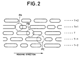
- Figure 2 illustrates the individual beam spots formed on the recording surface of the optical disc 1 by the three information reading beams.
- a beam spot PA is formed on an adjacent track (T+1).
- a beam spot PC is formed on another adjacent track (T-1) of the track T.
- the reflected lights from the beam spots PA, PB and PC reach a photosensor 7 via the objective lens 6 and the half mirror 5.
- the photosensor 7 performs photoelectric conversion on the reflected light of the beam spot PA, which has come via the half mirror 5, yielding a read signal RA.
- the photosensor 7 also performs photoelectric conversion on the reflected light of the beam spot PB, received via the half mirror 5, yielding a read signal RB.
- the photosensor 7 performs photoelectric conversion on the reflected light of the beam spot PC, received via the half mirror 5, yielding a read signal RC.
- the read signals RA, RB and RC are supplied to a servo system (not shown) which implements various servos, such as tracking servo, focus servo and spindle servo, and also supplied to A/D converters 8A to 8C, respectively.
- the A/D converters 8A-8C supplies a crosstalk canceler 10 with series of read sample values SA, SB and SC, which have been acquired by respectively sampling the read signals RA, RB and RC at every predetermined sampling clock.
- the frequency of the predetermined sampling clock is set to an integer multiple of the channel frequency of information signals recorded on the optical disc 1.
- the crosstalk canceler 10 performs adaptive signal processing on the series of read sample values SA, SB and SC using, for example, the LMS adaptive algorithm, thereby acquiring series of read sample values P whose waveforms are free of both the intersymbol interference and crosstalk, and sends the series of read sample values P to a decision unit 125.
- the decision unit 125 determines a reproduction signal corresponding to information recorded on the optical disc 1 from the received series of read sample values P, and outputs the reproduction signal.
- the crosstalk canceler 10 comprises variable coefficient filters 111 and 112, a subtracter 120, filter coefficient calculators 123 and 124, residual crosstalk extractors 131 and 132, and limiter circuits 127 and 128.
- variable coefficient filters 111 and 112 are comprised of, for example, a transversal filter as shown in Figure 3.
- the transversal filter comprises N stages of series D flip-flops D1 to Dn, coefficient multipliers M0 to Mn and an adder AD1.
- the D flip-flops D1-Dn latch a series of input sample values while shifting them.
- the coefficient multiplier M0 multiplies the series of input sample values by a filter coefficient C 0 .
- the coefficient multipliers M1-Mn respectively multiply the outputs of the D flip-flops D1-Dn by filter coefficients C 1 to C n .
- the adder AD1 adds all the values acquired by multiplication in the coefficient multipliers M0-Mn, and outputs the resultant value as a series of output sample values.
- variable coefficient filter 111 with the above configuration filters the series of read sample values SA using filter coefficients AC 0 to AC n supplied from the filter coefficient calculator 123, yielding a series of crosstalk sample values CR1 corresponding to the crosstalk component from one adjacent track (the track T+1 in Figure 2), and supplies the series of crosstalk sample values CR1 to the subtracter 120.
- the variable coefficient filter 112 filters the series of read sample values SC using filter coefficients CC 0 to CC n supplied from the filter coefficient calculator 123, yielding a series of crosstalk sample values CR2 corresponding to the crosstalk component from another adjacent track (the track T-1 in Figure 2), and supplies the series of crosstalk sample values CR2 to the subtracter 120.
- the subtracter 120 subtracts the series of crosstalk sample values CR1 and CR2 each from the series of read sample values R and sends the resultant signals as a series of read sample values P to the decision unit 125 and the residual crosstalk extractors 131 and 132, respectively.
- each of the crosstalk extractors 131 and 132 extract the value of the middle sample in the three samples or a zero-cross sample value, and sends it as an error signal E to the associated filter coefficient calculator 123 or 124.
- the filter coefficient calculator 123 correlates the series of read sample values SA with the error signal E, acquiring filter coefficients, and supplies the filter coefficients to the limiter circuit 127.
- the limiter circuit 127 controls the filter coefficients in such a way that the filter coefficients do not become smaller than a predetermined value set or greater than a predetermined value, and sends the filter coefficients AC 0 -AC n to the variable coefficient filter 111 as the filter coefficients C 0 -C n of the variable coefficient filter 111.
- the filter coefficient calculator 124 acquires filter coefficients on the basis of the series of read sample values SC and the error signal E, and supplies the filter coefficients to the limiter circuit 128.
- the limiter circuit 128 controls the filter coefficients in such a way that the filter coefficients do not become equal to or smaller than a predetermined value set or equal to or greater than the predetermined value, and send the filter coefficients CC 0 -CC n to the variable coefficient filter 112 as the filter coefficients C 0 -C n of the variable coefficient filter 112.
- the filter coefficient calculators 123 and 124 respectively update the filter coefficients AC 0 -AC n and CC 0 -CC n employing the LMS adaptive algorithm in such a manner that the error signal E converges to 0.
- Figure 4 is a diagram showing the internal structures of the filter coefficient calculator 123 and the limiter circuit 127 according to one embodiment of the present invention.
- the filter coefficient calculator 123 comprises N stages of series D flip-flops, DF1 to DFn, which latch a series of input sample values while shifting them, and multipliers MM0 to MMn.
- the multiplier MM0 sends correction values (the differences from the previous sample values), obtained by multiplying the series of input sample values SA by the error signal E and a correction coefficient p, to the limiter circuit 127.
- each of the coefficient multipliers MM1-MMn sends correction values (the differences from the previous sample values), obtained by multiplying the output of the associated one of the D flip-flops DF1-DFn by the error signal E and the correction coefficient ⁇ , to the limiter circuit 127.
- the limiter circuit 127 adds the currently obtained correction value to a previous coefficient value ACn stored in a register, and outputs the previous coefficient value ACn directly as filter coefficients AC 1 ' to AC n ' when the added value (sign bit) is negative. When the added value is not negative, the added value is output as the filter coefficients AC 1 ' to AC n '.
- the correction coefficient ⁇ is employed for adjusting the convergence characteristic of the LMS adaptive algorithm. Increasing the correction coefficient ⁇ increases a speed for the error signal E to be converged to zero at a price of possible divergence. Reducing the correction coefficient ⁇ , on the other hand, results in slower convergence while convergence is guaranteed.
- the filter coefficient calculator 124 and the limiter circuit 128, which are associated with the series of crosstalk sample values CR2 from the other adjacent track (the track T-1 in Figure 2) have the same structures as have been described above.
- the crosstalk canceler can ensure fast convergence of the filter coefficient values and can operate in a stable manner.
- Figure 5 is a block diagram illustrating the configuration of a crosstalk canceler 10 according to another embodiment of the present invention.
- the crosstalk canceler 10 comprises a variable coefficient filter 211, a subtracter 220, a filter coefficient calculator 223, a zero-cross sample value extractor 231, a reference value storage register 232, a reference value subtracter 233, and a limiter circuit 227.
- the limiter circuit 227 comprises a comparator 243, a memory 244 for storing a set value for restricting a filter coefficient, a switch 245 and a register 249 for storing the result of previous computation of the filter coefficient calculator 223.
- the subtracter 220 subtracts a series of crosstalk sample values CR from a series of read sample values R of a main signal (signal CENT) that is currently tracked, and sends the resultant signal as a series of read sample values P to the decision unit (not shown).
- the reference value subtracter 233 subtracts a set reference value (Ref) of a predetermined level from values sampled by the zero-cross sample value extractor 231, and sends the resultant value to the filter coefficient calculator 223.
- the filter coefficient calculator 223 acquires filter coefficients from a series of read sample values of a sub signal (signal SIDE) and the error signal E, and sends the filter coefficients to the limiter circuit 227.
- the comparator 243 of the limiter circuit 227 compares the filter coefficients with a predetermined minimum value or a predetermined maximum value stored in advance in the memory 244.
- the comparator 243 causes the switch 245 to operate to supply the currently acquired filter coefficients as the filter coefficients C 0 -C n to the variable coefficient filter 211.
- the switch 245 is operated to supply the previously acquired filter coefficients, stored in the register 249, as the filter coefficients C 0 -C n to the variable coefficient filter 211.
- the above-described operation can restrict the filter coefficients C 0 -C n to be supplied to the variable coefficient filter 211 within a range of predetermined set values.
- a value that can be regarded substantially to be zero relative to the other filter coefficients may be used as the predetermined minimum value.
- the maximum crosstalk value that has been measured in advance may be set as the predetermined maximum value.
- any empirical value which ensures good convergence may be used as the minimum value or the maximum value.
- the present invention can realize a crosstalk canceler which can ensure fast convergence of the values of filter coefficients and can achieve stable operation by controlling the filter coefficients within a predetermined value range.
- limiter circuit has been described as having a hardware configuration in the foregoing description of the embodiments, it can easily be accomplished by software in a microcomputer.
- a single beam which covers adjacent tracks may be used.
- a single beam may be split into a main signal (signal CENT) and a sub signal (signal SIDE) by means of a photosensor which is divided into three parts.
- the present invention can provide a recorded information reproducing apparatus having a crosstalk canceler which can ensure fast convergence of the values of filter coefficients of an adaptive digital filter and thereby achieving stable operation.
Abstract
Description
- The present invention relates to a recorded information reproducing apparatus and, more particularly, to a recorded information reproducing apparatus that reads out recorded information from a recording medium and reproduces the information.
- High-density information recording on a recording medium such as an optical disc can be realized by shortening a pit length and/or narrowing a track pitch. However, narrowing the track pitch of the optical disc causes crosstalk between signals on adjacent tracks when information is read out. Such a crosstalk prevents a read signal from having a desired waveform, so that a highly reliable reproduction signal cannot be obtained from the read signal.
- In this respect, a recorded information reproducing apparatus may perform an adaptive signal processing for a cancellation of the crosstalk.
- For example, a recorded information reproducing apparatus disclosed in Japanese Unexamined Patent Publication (Kokai) No. H9-320200 is designed to cancel a crosstalk by using signals read from three adjoining tracks with a 3-beam optical pick-up.
- More specifically, a crosstalk canceler employs adaptive signal processing, which is performed by an adaptive digital filter based on, for example, an LMS (Least Mean Square) adaptive algorithm. First, intersymbol interference is removed from a read signal that has been read from a track T with the center beam spot to obtain a series of read sample values R. Then, two series of crosstalk sample values CR1 and CR2 corresponding to crosstalk components of the tracks adjacent to the track T are acquired through the adaptive signal processing on the basis of the read signals. A series of read sample values P free from crosstalk are obtained by subtracting the series of crosstalk sample values CR1 and CR2 from the series of read sample values R.
- In this case, when three consecutive values in the series of the sample values P changes from positive to negative or from negative to positive, the middle of the three sample values, i.e., a zero-cross sample value, is extracted as an error signal E. The filter coefficient of the digital filter, in turn, is updated in accordance with the intensity of the error signal E.
- In other words, when a read signal is waveform-equalized so as to meet the Nyquist's second bandwidth requirement and is free of a crosstalk, the read signal crosses zero at the time it is sampled. When a crosstalk occurs, however, the waveform of the read signal is changed so that the read signal will not cross zero at the sampling time.
- When a sample value at the zero-crossing time (i.e., zero-crossing sample value) is not zero, it is determined that a crosstalk corresponding to the error occurs. The conventional recorded information reproducing apparatus is constructed to update the filter coefficient of a variable coefficient filter so as to make the zero-crossing sample value corresponding to the error converges to zero.
- Under certain circumstances for a crosstalk intensity, however, it may occur that the filter coefficients, which should be positive values in principle, are obtained as negative values, or that a calculation of the coefficients take a considerable time to converge. In the worst case, overflow in the crosstalk canceler may occur, thereby causing the canceler to operate unstable.
- Accordingly, it is an object of the present invention to provide a recorded information reproducing apparatus having a crosstalk canceler capable of ensuring fast convergence of the filter coefficients of an adaptive digital filter and thereby achieving stable operation.
- A recorded information reproducing apparatus according to the present invention comprises reading means for reading recorded information from one track on a recording medium to acquire a first read signal, and for reading recorded information from at least one track adjacent to the one track to acquire a second read signal; operating means for operating at least one coefficient on the second read signal; subtracting means for subtracting an output of the operating means from the first read signal; and coefficient setting means for setting at least one coefficient and for restricting at least one coefficient in such a way that the at least one coefficient becomes greater than a first predetermined value or smaller than a second predetermined value.
-
- Figure 1 is a diagram illustrating the configuration of a recorded information reproducing apparatus embodying the present invention ;
- Figure 2 is a diagram showing tracks on the recording surface of an optical disc and reading beam spots;
- Figure 3 is a diagram depicting the structure of a transversal filter;
- Figure 4 is a diagram showing the internal structures of a filter coefficient calculator and a limiter circuit according to one embodiment of the present invention; and
- Figure 5 is a block diagram illustrating the configuration of a crosstalk canceler according to another embodiment of the present invention .
-
- Preferred embodiments of the present invention will now be described referring to the accompanying drawings.
- Figure 1 illustrates the configuration of a recorded information reproducing apparatus embodying the present invention .
- Referring to Figure 1, a laser beam emitted from a laser oscillator 3 is split into three beams via a grating lens 4. The three beams are respectively irradiated on three adjacent tracks of an
optical disc 1 through ahalf mirror 5 and an objective lens 6. Aspindle motor 2 rotates theoptical disc 1. - Figure 2 illustrates the individual beam spots formed on the recording surface of the
optical disc 1 by the three information reading beams. - When the central beam spot, PB, is formed on a track T, as shown in Figure 2, a beam spot PA is formed on an adjacent track (T+1). Further, a beam spot PC is formed on another adjacent track (T-1) of the track T. The reflected lights from the beam spots PA, PB and PC reach a photosensor 7 via the objective lens 6 and the
half mirror 5. The photosensor 7 performs photoelectric conversion on the reflected light of the beam spot PA, which has come via thehalf mirror 5, yielding a read signal RA. The photosensor 7 also performs photoelectric conversion on the reflected light of the beam spot PB, received via thehalf mirror 5, yielding a read signal RB. Likewise, the photosensor 7 performs photoelectric conversion on the reflected light of the beam spot PC, received via thehalf mirror 5, yielding a read signal RC. The read signals RA, RB and RC are supplied to a servo system (not shown) which implements various servos, such as tracking servo, focus servo and spindle servo, and also supplied to A/D converters 8A to 8C, respectively. - The A/
D converters 8A-8C supplies acrosstalk canceler 10 with series of read sample values SA, SB and SC, which have been acquired by respectively sampling the read signals RA, RB and RC at every predetermined sampling clock. - It is to be noted that the frequency of the predetermined sampling clock is set to an integer multiple of the channel frequency of information signals recorded on the
optical disc 1. - The
crosstalk canceler 10 performs adaptive signal processing on the series of read sample values SA, SB and SC using, for example, the LMS adaptive algorithm, thereby acquiring series of read sample values P whose waveforms are free of both the intersymbol interference and crosstalk, and sends the series of read sample values P to adecision unit 125. Thedecision unit 125 determines a reproduction signal corresponding to information recorded on theoptical disc 1 from the received series of read sample values P, and outputs the reproduction signal. - The internal configuration of the
crosstalk canceler 10 will now be discussed. - The
crosstalk canceler 10 comprisesvariable coefficient filters subtracter 120,filter coefficient calculators residual crosstalk extractors limiter circuits - Each of the
variable coefficient filters - The transversal filter comprises N stages of series D flip-flops D1 to Dn, coefficient multipliers M0 to Mn and an adder AD1. The D flip-flops D1-Dn latch a series of input sample values while shifting them. The coefficient multiplier M0 multiplies the series of input sample values by a filter coefficient C0. The coefficient multipliers M1-Mn respectively multiply the outputs of the D flip-flops D1-Dn by filter coefficients C1 to Cn. The adder AD1 adds all the values acquired by multiplication in the coefficient multipliers M0-Mn, and outputs the resultant value as a series of output sample values.
- The
variable coefficient filter 111 with the above configuration filters the series of read sample values SA using filter coefficients AC0 to ACn supplied from thefilter coefficient calculator 123, yielding a series of crosstalk sample values CR1 corresponding to the crosstalk component from one adjacent track (the track T+1 in Figure 2), and supplies the series of crosstalk sample values CR1 to thesubtracter 120. Thevariable coefficient filter 112 filters the series of read sample values SC using filter coefficients CC0 to CCn supplied from thefilter coefficient calculator 123, yielding a series of crosstalk sample values CR2 corresponding to the crosstalk component from another adjacent track (the track T-1 in Figure 2), and supplies the series of crosstalk sample values CR2 to thesubtracter 120. - The
subtracter 120 subtracts the series of crosstalk sample values CR1 and CR2 each from the series of read sample values R and sends the resultant signals as a series of read sample values P to thedecision unit 125 and theresidual crosstalk extractors - When the value of any of three consecutive samples in the series of waveform-equalized read sample values P changes from positive to negative or from negative to positive, each of the
crosstalk extractors filter coefficient calculator - The
filter coefficient calculator 123 correlates the series of read sample values SA with the error signal E, acquiring filter coefficients, and supplies the filter coefficients to thelimiter circuit 127. Thelimiter circuit 127 controls the filter coefficients in such a way that the filter coefficients do not become smaller than a predetermined value set or greater than a predetermined value, and sends the filter coefficients AC0-ACn to thevariable coefficient filter 111 as the filter coefficients C0-Cn of thevariable coefficient filter 111. - The
filter coefficient calculator 124 acquires filter coefficients on the basis of the series of read sample values SC and the error signal E, and supplies the filter coefficients to thelimiter circuit 128. Thelimiter circuit 128 controls the filter coefficients in such a way that the filter coefficients do not become equal to or smaller than a predetermined value set or equal to or greater than the predetermined value, and send the filter coefficients CC0-CCn to thevariable coefficient filter 112 as the filter coefficients C0-Cn of thevariable coefficient filter 112. - The
filter coefficient calculators - Figure 4 is a diagram showing the internal structures of the
filter coefficient calculator 123 and thelimiter circuit 127 according to one embodiment of the present invention. - For example, the
filter coefficient calculator 123 comprises N stages of series D flip-flops, DF1 to DFn, which latch a series of input sample values while shifting them, and multipliers MM0 to MMn. The multiplier MM0 sends correction values (the differences from the previous sample values), obtained by multiplying the series of input sample values SA by the error signal E and a correction coefficient p, to thelimiter circuit 127. Likewise, each of the coefficient multipliers MM1-MMn sends correction values (the differences from the previous sample values), obtained by multiplying the output of the associated one of the D flip-flops DF1-DFn by the error signal E and the correction coefficient µ, to thelimiter circuit 127. Thelimiter circuit 127 adds the currently obtained correction value to a previous coefficient value ACn stored in a register, and outputs the previous coefficient value ACn directly as filter coefficients AC1' to ACn' when the added value (sign bit) is negative. When the added value is not negative, the added value is output as the filter coefficients AC1' to ACn'. - The correction coefficient µ is employed for adjusting the convergence characteristic of the LMS adaptive algorithm. Increasing the correction coefficient µ increases a speed for the error signal E to be converged to zero at a price of possible divergence. Reducing the correction coefficient µ, on the other hand, results in slower convergence while convergence is guaranteed.
- The
filter coefficient calculator 124 and thelimiter circuit 128, which are associated with the series of crosstalk sample values CR2 from the other adjacent track (the track T-1 in Figure 2) have the same structures as have been described above. - As explained above, designed to control the filter coefficients not to be negative, the crosstalk canceler can ensure fast convergence of the filter coefficient values and can operate in a stable manner.
- Figure 5 is a block diagram illustrating the configuration of a
crosstalk canceler 10 according to another embodiment of the present invention. - The
crosstalk canceler 10 comprises avariable coefficient filter 211, asubtracter 220, afilter coefficient calculator 223, a zero-crosssample value extractor 231, a referencevalue storage register 232, areference value subtracter 233, and alimiter circuit 227. Thelimiter circuit 227 comprises acomparator 243, amemory 244 for storing a set value for restricting a filter coefficient, aswitch 245 and aregister 249 for storing the result of previous computation of thefilter coefficient calculator 223. - The operation of the
crosstalk canceler 10 according to the embodiment will be discussed below. - The
subtracter 220 subtracts a series of crosstalk sample values CR from a series of read sample values R of a main signal (signal CENT) that is currently tracked, and sends the resultant signal as a series of read sample values P to the decision unit (not shown). - The
reference value subtracter 233 subtracts a set reference value (Ref) of a predetermined level from values sampled by the zero-crosssample value extractor 231, and sends the resultant value to thefilter coefficient calculator 223. Thefilter coefficient calculator 223 acquires filter coefficients from a series of read sample values of a sub signal (signal SIDE) and the error signal E, and sends the filter coefficients to thelimiter circuit 227. Thecomparator 243 of thelimiter circuit 227 compares the filter coefficients with a predetermined minimum value or a predetermined maximum value stored in advance in thememory 244. When the values of the filter coefficients are equal to or greater than the predetermined minimum value, or are equal to or smaller than the predetermined maximum value, or lie within the values, thecomparator 243 causes theswitch 245 to operate to supply the currently acquired filter coefficients as the filter coefficients C0-Cn to thevariable coefficient filter 211. When the currently acquired values of the filter coefficients are not equal to or greater than the predetermined minimum value, or are not equal to or smaller than the predetermined maximum value, or do not lie within the values, theswitch 245 is operated to supply the previously acquired filter coefficients, stored in theregister 249, as the filter coefficients C0-Cn to thevariable coefficient filter 211. The above-described operation can restrict the filter coefficients C0-Cn to be supplied to thevariable coefficient filter 211 within a range of predetermined set values. - In this case, a value that can be regarded substantially to be zero relative to the other filter coefficients may be used as the predetermined minimum value. The maximum crosstalk value that has been measured in advance may be set as the predetermined maximum value. Alternatively, any empirical value which ensures good convergence may be used as the minimum value or the maximum value.
- As apparent from the above, the present invention can realize a crosstalk canceler which can ensure fast convergence of the values of filter coefficients and can achieve stable operation by controlling the filter coefficients within a predetermined value range.
- Although the limiter circuit has been described as having a hardware configuration in the foregoing description of the embodiments, it can easily be accomplished by software in a microcomputer.
- Although the foregoing description of the embodiments has been given with reference to a crosstalk canceler that uses three beams, the present invention is not limited to the particular case but a single beam which covers adjacent tracks may be used. In this case, a single beam may be split into a main signal (signal CENT) and a sub signal (signal SIDE) by means of a photosensor which is divided into three parts.
- While the foregoing description of the embodiments has been given with reference to a case where extraction of a residual crosstalk is implemented by using zero-cross sample values, the present invention is not limited to the particular case. The structure may be modified to acquire the amount of the residual crosstalk.
- As described in detail above, as the values of filter coefficients are properly controlled, the present invention can provide a recorded information reproducing apparatus having a crosstalk canceler which can ensure fast convergence of the values of filter coefficients of an adaptive digital filter and thereby achieving stable operation.
Claims (7)
- A recorded information reproducing apparatus comprising:reading means for reading recorded information from one track on a recording medium to acquire a first read signal, and for reading recorded information from at least one track adjacent to said one track to acquire a second read signal;operating means for operating at least one coefficient on said second read signal;subtracting means for subtracting an output of said operating means from said first read signal; andcoefficient setting means for setting said at least one coefficient and for restricting said at least one coefficient in such a way that said at least one coefficient becomes greater than a first predetermined value or smaller than a second predetermined value.
- The recorded information reproducing apparatus according to claim 1, wherein said coefficient setting means restricts said at least one coefficient in such a manner that said at least one coefficient does not become negative.
- The recorded information reproducing apparatus according to claim 1, wherein said coefficient setting means restricts said at least one coefficient in such a manner that said at least one coefficient does not exceed a predetermined maximum value.
- The recorded information reproducing apparatus according to claim 1, wherein said coefficient setting means sets a plurality of coefficients, and restricts said plurality of coefficients in such a manner that with respect to one of said plurality of coefficients, the other coefficients do not become substantially zero; and
said operating means operating said plurality of coefficients on said second read signal. - The recorded information reproducing apparatus according to claim 1, wherein said reading means sets read signals read from two adjoining tracks on both sides of said one track as said second read signal.
- The recorded information reproducing apparatus according to claim 1, wherein said operating means comprises at least one transversal filter.
- The recorded information reproducing apparatus according to claim 1, wherein said coefficient setting means sets said at least one coefficient using an output of said operating means, obtained through adaptive signal processing based on an LMS (Least Mean Square) adaptive algorithm, as a crosstalk signal.
Applications Claiming Priority (2)
| Application Number | Priority Date | Filing Date | Title |
|---|---|---|---|
| JP10210897A JP2000048488A (en) | 1998-07-27 | 1998-07-27 | Recording information reproducing device having cross talk removal circuit |
| JP21089798 | 1998-07-27 |
Publications (3)
| Publication Number | Publication Date |
|---|---|
| EP0977183A2 true EP0977183A2 (en) | 2000-02-02 |
| EP0977183A3 EP0977183A3 (en) | 2001-09-19 |
| EP0977183B1 EP0977183B1 (en) | 2005-10-26 |
Family
ID=16596899
Family Applications (1)
| Application Number | Title | Priority Date | Filing Date |
|---|---|---|---|
| EP99305453A Expired - Lifetime EP0977183B1 (en) | 1998-07-27 | 1999-07-08 | Recorded information reproducing apparatus with crosstalk canceler |
Country Status (5)
| Country | Link |
|---|---|
| US (1) | US6580676B1 (en) |
| EP (1) | EP0977183B1 (en) |
| JP (1) | JP2000048488A (en) |
| DE (1) | DE69927886T2 (en) |
| HK (1) | HK1023643A1 (en) |
Cited By (3)
| Publication number | Priority date | Publication date | Assignee | Title |
|---|---|---|---|---|
| WO2005050630A2 (en) * | 2003-11-18 | 2005-06-02 | Koninklijke Philips Electronics N.V. | Apparatus and method for reading information from an information carrier |
| CN107210049A (en) * | 2015-02-12 | 2017-09-26 | 索尼公司 | Optical medium transcriber and optical medium reproducting method |
| US10134438B2 (en) | 2013-06-28 | 2018-11-20 | Sony Corporation | Optical medium reproduction apparatus and method of reproducing optical medium |
Families Citing this family (16)
| Publication number | Priority date | Publication date | Assignee | Title |
|---|---|---|---|---|
| JP2002298364A (en) * | 2001-03-30 | 2002-10-11 | Pioneer Electronic Corp | Information reproducing device, signal processor and information reproducing method |
| US7304918B2 (en) * | 2003-09-24 | 2007-12-04 | Matsushita Electric Industrial Co., Ltd. | Servo error signal generation circuit and servo error signal generation method |
| US8659846B2 (en) | 2010-10-29 | 2014-02-25 | Sk Hynix Memory Solutions Inc. | Inter-track interference cancelation in the presence of frequency offset |
| US8665543B2 (en) * | 2010-10-29 | 2014-03-04 | Sk Hynix Memory Solutions Inc. | Inter-track interference cancelation for shingled magnetic recording |
| WO2014057674A1 (en) * | 2012-10-11 | 2014-04-17 | パナソニック株式会社 | Optical information device, cross-talk reduction method, computer, player, and recorder |
| JP6388214B2 (en) | 2013-06-19 | 2018-09-12 | パナソニックIpマネジメント株式会社 | Optical information apparatus and information processing apparatus |
| WO2014203527A1 (en) | 2013-06-21 | 2014-12-24 | パナソニックIpマネジメント株式会社 | Optical disc information device and information processing device |
| CN105453177B (en) * | 2013-08-14 | 2019-06-28 | 索尼公司 | Optical medium transcriber and optical medium reproducting method |
| JP6167918B2 (en) | 2013-08-14 | 2017-07-26 | ソニー株式会社 | Optical medium reproducing apparatus and optical medium reproducing method |
| US10014026B1 (en) * | 2017-06-20 | 2018-07-03 | Seagate Technology Llc | Head delay calibration and tracking in MSMR systems |
| US11016681B1 (en) | 2018-07-31 | 2021-05-25 | Seagate Technology Llc | Multi-threshold parameter adaptation |
| US10522177B1 (en) | 2018-07-31 | 2019-12-31 | Seagate Technology Llc | Disc locked clock-based servo timing |
| US11018842B1 (en) | 2018-07-31 | 2021-05-25 | Seagate Technology Llc | Dynamic timing recovery bandwidth modulation for phase offset mitigation |
| US10803902B1 (en) | 2018-08-19 | 2020-10-13 | Seagate Technology Llc | Hardware-based read sample averaging |
| US10460762B1 (en) | 2018-09-04 | 2019-10-29 | Seagate Technology Llc | Cancelling adjacent track interference signal with different data rate |
| US10468060B1 (en) | 2018-09-27 | 2019-11-05 | Seagate Technology Llc | Cancelling adjacent track interference |
Citations (3)
| Publication number | Priority date | Publication date | Assignee | Title |
|---|---|---|---|---|
| US5483515A (en) * | 1994-09-16 | 1996-01-09 | International Business Machines Corporation | Apparatus and method for cancelling cross-talk in signals from optical data storage systems |
| US5587985A (en) * | 1993-03-09 | 1996-12-24 | Matsushita Electric Industrial Co., Ltd. | Signal processing device for an optical information reproducing apparatus |
| JPH09320200A (en) * | 1996-05-30 | 1997-12-12 | Pioneer Electron Corp | Recording information reproducing device |
Family Cites Families (5)
| Publication number | Priority date | Publication date | Assignee | Title |
|---|---|---|---|---|
| JP3258452B2 (en) * | 1992-07-21 | 2002-02-18 | パイオニア株式会社 | Optical disk signal reproduction device |
| JPH0969230A (en) * | 1995-08-31 | 1997-03-11 | Sony Corp | Optical disk, device and method for recording and reproducing optical disk |
| JP3800653B2 (en) * | 1995-12-26 | 2006-07-26 | ソニー株式会社 | Crosstalk removal device |
| JP3526185B2 (en) * | 1997-10-07 | 2004-05-10 | パイオニア株式会社 | Crosstalk removing device in recorded information reproducing device |
| JPH11144252A (en) * | 1997-11-11 | 1999-05-28 | Pioneer Electron Corp | Crosstalk eliminating method for recorded information reproducing device |
-
1998
- 1998-07-27 JP JP10210897A patent/JP2000048488A/en active Pending
-
1999
- 1999-07-08 DE DE69927886T patent/DE69927886T2/en not_active Expired - Fee Related
- 1999-07-08 EP EP99305453A patent/EP0977183B1/en not_active Expired - Lifetime
- 1999-07-19 US US09/356,676 patent/US6580676B1/en not_active Expired - Fee Related
-
2000
- 2000-05-16 HK HK00102711A patent/HK1023643A1/en not_active IP Right Cessation
Patent Citations (3)
| Publication number | Priority date | Publication date | Assignee | Title |
|---|---|---|---|---|
| US5587985A (en) * | 1993-03-09 | 1996-12-24 | Matsushita Electric Industrial Co., Ltd. | Signal processing device for an optical information reproducing apparatus |
| US5483515A (en) * | 1994-09-16 | 1996-01-09 | International Business Machines Corporation | Apparatus and method for cancelling cross-talk in signals from optical data storage systems |
| JPH09320200A (en) * | 1996-05-30 | 1997-12-12 | Pioneer Electron Corp | Recording information reproducing device |
Non-Patent Citations (1)
| Title |
|---|
| PATENT ABSTRACTS OF JAPAN vol. 1998, no. 04, 31 March 1998 (1998-03-31) & JP 09 320200 A (PIONEER ELECTRON CORP), 12 December 1997 (1997-12-12) -& US 5 835 468 A (TOMITA YOSHIMI ET AL) 10 November 1998 (1998-11-10) * |
Cited By (5)
| Publication number | Priority date | Publication date | Assignee | Title |
|---|---|---|---|---|
| WO2005050630A2 (en) * | 2003-11-18 | 2005-06-02 | Koninklijke Philips Electronics N.V. | Apparatus and method for reading information from an information carrier |
| WO2005050630A3 (en) * | 2003-11-18 | 2008-01-17 | Koninkl Philips Electronics Nv | Apparatus and method for reading information from an information carrier |
| US10134438B2 (en) | 2013-06-28 | 2018-11-20 | Sony Corporation | Optical medium reproduction apparatus and method of reproducing optical medium |
| CN107210049A (en) * | 2015-02-12 | 2017-09-26 | 索尼公司 | Optical medium transcriber and optical medium reproducting method |
| CN107210049B (en) * | 2015-02-12 | 2020-09-01 | 索尼公司 | Optical medium reproducing apparatus and optical medium reproducing method |
Also Published As
| Publication number | Publication date |
|---|---|
| DE69927886T2 (en) | 2006-07-20 |
| HK1023643A1 (en) | 2000-09-15 |
| DE69927886D1 (en) | 2005-12-01 |
| US6580676B1 (en) | 2003-06-17 |
| EP0977183A3 (en) | 2001-09-19 |
| JP2000048488A (en) | 2000-02-18 |
| EP0977183B1 (en) | 2005-10-26 |
Similar Documents
| Publication | Publication Date | Title |
|---|---|---|
| EP0977183B1 (en) | Recorded information reproducing apparatus with crosstalk canceler | |
| US5835467A (en) | Apparatus for reproducing recorded information | |
| KR930002879B1 (en) | Data recording/reproducing apparatus with 2-dimension equalizer for reducing crosstalk | |
| EP0393719B1 (en) | Signal reproducing apparatus for optical recording and reproducing equipment and method for the same | |
| US7116504B1 (en) | DC-offset compensation loops for magnetic recording system | |
| US5729514A (en) | Cross talk removing device utilizing signal from main track to subtract amplitude adjusted signals from adjacent tracks | |
| US7349321B2 (en) | Information reproduction apparatus and information reproduction method | |
| US7218581B2 (en) | Asynchronous crosstalk cancellation | |
| US6577568B1 (en) | Optical disk apparatus using tilt and aberration correction control system | |
| JPH06295540A (en) | Digital signal detection circuit | |
| US20070041300A1 (en) | Optical disk apparatus and reproduction signal processing circuit | |
| JP3871906B2 (en) | Reproduction power control method, reproduction power control apparatus, and recording / reproduction apparatus including the same | |
| US6163518A (en) | Crosstalk eliminating method for use in a recorded information reproducing apparatus | |
| JP3497724B2 (en) | Tracking control device | |
| KR19980020547A (en) | Digital beat player for optical disc player | |
| US5666339A (en) | Optical information reproducing apparatus using transversal filter | |
| JP2760099B2 (en) | Optical recording / reproducing device | |
| JP2001014804A (en) | Adaptive equalizer and optical disk device using the same | |
| US6810000B2 (en) | Clock generator having a crosstalk removing circuit for use in a recording information reproduction apparatus | |
| JP2000113595A (en) | Crosstalk removing method and crosstalk removing device | |
| JP2550727B2 (en) | Optical disk recording and playback device | |
| KR100533749B1 (en) | Equalization Control Device and Method of Optical Disc Player | |
| JP2000311350A (en) | Automatic gain controller, automatic gain control method and optical disk device | |
| JPH1153736A (en) | Optical disk device and optical disk access method | |
| JP2001110145A (en) | Device for reproducing recorded information |
Legal Events
| Date | Code | Title | Description |
|---|---|---|---|
| PUAI | Public reference made under article 153(3) epc to a published international application that has entered the european phase |
Free format text: ORIGINAL CODE: 0009012 |
|
| AK | Designated contracting states |
Kind code of ref document: A2 Designated state(s): AT BE CH CY DE DK ES FI FR GB GR IE IT LI LU MC NL PT SE Kind code of ref document: A2 Designated state(s): DE FR GB |
|
| AX | Request for extension of the european patent |
Free format text: AL;LT;LV;MK;RO;SI |
|
| PUAL | Search report despatched |
Free format text: ORIGINAL CODE: 0009013 |
|
| AK | Designated contracting states |
Kind code of ref document: A3 Designated state(s): AT BE CH CY DE DK ES FI FR GB GR IE IT LI LU MC NL PT SE |
|
| AX | Request for extension of the european patent |
Free format text: AL;LT;LV;MK;RO;SI |
|
| RIC1 | Information provided on ipc code assigned before grant |
Free format text: 7G 11B 7/00 A, 7G 11B 20/10 B |
|
| 17P | Request for examination filed |
Effective date: 20011114 |
|
| AKX | Designation fees paid |
Free format text: DE FR GB |
|
| GRAP | Despatch of communication of intention to grant a patent |
Free format text: ORIGINAL CODE: EPIDOSNIGR1 |
|
| GRAS | Grant fee paid |
Free format text: ORIGINAL CODE: EPIDOSNIGR3 |
|
| GRAA | (expected) grant |
Free format text: ORIGINAL CODE: 0009210 |
|
| AK | Designated contracting states |
Kind code of ref document: B1 Designated state(s): DE FR GB |
|
| REG | Reference to a national code |
Ref country code: GB Ref legal event code: FG4D |
|
| REF | Corresponds to: |
Ref document number: 69927886 Country of ref document: DE Date of ref document: 20051201 Kind code of ref document: P |
|
| REG | Reference to a national code |
Ref country code: HK Ref legal event code: GR Ref document number: 1023643 Country of ref document: HK |
|
| PGFP | Annual fee paid to national office [announced via postgrant information from national office to epo] |
Ref country code: GB Payment date: 20060705 Year of fee payment: 8 |
|
| REG | Reference to a national code |
Ref country code: GB Ref legal event code: 746 Effective date: 20060612 |
|
| PGFP | Annual fee paid to national office [announced via postgrant information from national office to epo] |
Ref country code: DE Payment date: 20060706 Year of fee payment: 8 |
|
| ET | Fr: translation filed | ||
| PLBE | No opposition filed within time limit |
Free format text: ORIGINAL CODE: 0009261 |
|
| STAA | Information on the status of an ep patent application or granted ep patent |
Free format text: STATUS: NO OPPOSITION FILED WITHIN TIME LIMIT |
|
| 26N | No opposition filed |
Effective date: 20060727 |
|
| GBPC | Gb: european patent ceased through non-payment of renewal fee |
Effective date: 20070708 |
|
| PG25 | Lapsed in a contracting state [announced via postgrant information from national office to epo] |
Ref country code: DE Free format text: LAPSE BECAUSE OF NON-PAYMENT OF DUE FEES Effective date: 20080201 |
|
| PG25 | Lapsed in a contracting state [announced via postgrant information from national office to epo] |
Ref country code: GB Free format text: LAPSE BECAUSE OF NON-PAYMENT OF DUE FEES Effective date: 20070708 |
|
| REG | Reference to a national code |
Ref country code: FR Ref legal event code: ST Effective date: 20080331 |
|
| PG25 | Lapsed in a contracting state [announced via postgrant information from national office to epo] |
Ref country code: FR Free format text: LAPSE BECAUSE OF NON-PAYMENT OF DUE FEES Effective date: 20070731 |
|
| PG25 | Lapsed in a contracting state [announced via postgrant information from national office to epo] |
Ref country code: FR Free format text: LAPSE BECAUSE OF NON-PAYMENT OF DUE FEES Effective date: 20060731 |