EP0976878A2 - Load handling apparatus - Google Patents
Load handling apparatus Download PDFInfo
- Publication number
- EP0976878A2 EP0976878A2 EP99113846A EP99113846A EP0976878A2 EP 0976878 A2 EP0976878 A2 EP 0976878A2 EP 99113846 A EP99113846 A EP 99113846A EP 99113846 A EP99113846 A EP 99113846A EP 0976878 A2 EP0976878 A2 EP 0976878A2
- Authority
- EP
- European Patent Office
- Prior art keywords
- cab
- ground engaging
- axle
- operator
- engaging means
- Prior art date
- Legal status (The legal status is an assumption and is not a legal conclusion. Google has not performed a legal analysis and makes no representation as to the accuracy of the status listed.)
- Granted
Links
Images


Classifications
-
- B—PERFORMING OPERATIONS; TRANSPORTING
- B66—HOISTING; LIFTING; HAULING
- B66F—HOISTING, LIFTING, HAULING OR PUSHING, NOT OTHERWISE PROVIDED FOR, e.g. DEVICES WHICH APPLY A LIFTING OR PUSHING FORCE DIRECTLY TO THE SURFACE OF A LOAD
- B66F9/00—Devices for lifting or lowering bulky or heavy goods for loading or unloading purposes
- B66F9/06—Devices for lifting or lowering bulky or heavy goods for loading or unloading purposes movable, with their loads, on wheels or the like, e.g. fork-lift trucks
- B66F9/065—Devices for lifting or lowering bulky or heavy goods for loading or unloading purposes movable, with their loads, on wheels or the like, e.g. fork-lift trucks non-masted
- B66F9/0655—Devices for lifting or lowering bulky or heavy goods for loading or unloading purposes movable, with their loads, on wheels or the like, e.g. fork-lift trucks non-masted with a telescopic boom
-
- B—PERFORMING OPERATIONS; TRANSPORTING
- B66—HOISTING; LIFTING; HAULING
- B66F—HOISTING, LIFTING, HAULING OR PUSHING, NOT OTHERWISE PROVIDED FOR, e.g. DEVICES WHICH APPLY A LIFTING OR PUSHING FORCE DIRECTLY TO THE SURFACE OF A LOAD
- B66F9/00—Devices for lifting or lowering bulky or heavy goods for loading or unloading purposes
- B66F9/06—Devices for lifting or lowering bulky or heavy goods for loading or unloading purposes movable, with their loads, on wheels or the like, e.g. fork-lift trucks
- B66F9/075—Constructional features or details
- B66F9/12—Platforms; Forks; Other load supporting or gripping members
- B66F9/14—Platforms; Forks; Other load supporting or gripping members laterally movable, e.g. swingable, for slewing or transverse movements
- B66F9/142—Movements of forks either individually or relative to each other
Definitions
- This invention relates to a load handling apparatus of the kind which is movable under its own power over the ground and has a loader arm, or arms, which carries a loading implement.
- Such apparatus are popularly used for examples only on building sites to load and unload building materials etc., and in the agricultural industry for loading and unloading agricultural materials.
- Loader arms are known which are telescopic to allow greater reach. To enable an operator to have a sufficiently clear view for safe working when the arm is telescoped outwardly for example and a load is being handled at height, it is essential that the operator is as high up as possible. However this restricts the ability of the apparatus to be used in environments where height is restricted, such as within a freight container.
- a load handling apparatus including a body, a power operated motive means, a front axle and a rear axle, the axles each carrying ground engaging means on which the apparatus may move over the ground, at least one loader arm supported at or adjacent one end on the body for movement about a generally horizontal axis, the loader arm being adapted to carry a loading implement at or adjacent a second end thereof, the apparatus further including an operator's cab, characterised in that means are provided to move the cab generally upwardly and downwardly between upper and lower positions relative to the ground engaging means.
- a load handling apparatus which is capable of working in an environment where height is restricted, e.g. with the operator's cab in the lower position, and in situations where the operator's cab needs to be at an elevated height, i.e. in the upper position for safe working.
- the top of the cab will be the restricting factor on the height of the apparatus at least when the operator's cab is in the upper position and the loader arm is in a lowered position, but when in the lower position the top of the operator's cab may be lower than another part of the apparatus such as the uppermost part of the lowered loader arm.
- the operator's cab is provided at or adjacent a front end of the body.
- the body may be lifted and lowered relative to the ground engaging means, preferably the body provides a mounting means on which the operator's cab is carried for movement upwardly and downwardly whereby the operator's cab is moveable upwardly and downwardly relative to the body of the apparatus.
- a mounting means may for example comprise a guide means and the operator's cab may comprise a follower means, there being actuator means such as one or more fluid operated actuators or one or more mechanical drives, such as one or more threaded lead screws, to move the follower means relative to the guide means.
- the loader arm extends forwardly of the operator's cab and the generally horizontal axis about which the loader arm moves, is located rearwardly of the operator's cab.
- the power operated motive means may comprise an engine mounted generally rearwardly of the body, and there being a transmission, which may for examples be mechanical or hydrostatic or a hybrid of both, to transmit drive to the ground engaging means carried by at least one of the front and rear axles.
- the loader arm may be mounted at or adjacent one side of the body and the operator's cab may be located generally at an opposite side of the body so that the loader arm may be lifted and lowered about the generally horizontal axis, which may be located above the level of the ground engaging means, by the side of the operator's cab.
- the ground engaging means of the front axle or the rear axle is steerable.
- the ground engaging means of both the front and rear axles are steerable although preferably means are provided to lock the ground engaging means of one of the front and rear axles in a set position, usually straight ahead, so as to achieve steering only with a fully steerable ground engaging means of one of the axles when required.
- the fully steerable ground engaging means with which such locking means is not provided is preferably steered by means of a mechanical connection with a steering control operated from within the operator's cab, so that the apparatus complies with legislation which demands mechanical steering for on-road use, at least above a minimum speed.
- the apparatus may be used on rough terrain and driven on the road like a conventional vehicle at speeds exceeding those set for conventional load handling apparatus which have fluid operated steering.
- the fully steerable ground engaging means may be on the front axle and the mechanical connection includes a telescopic assembly whereby the mechanical connection is retained as the operator's cab is lifted and lowered.
- the telescopic assembly may for example include a splined shaft and a correspondingly splined receiving member which can relatively telescope and retain a driving connection.
- Power means such as fluid operated power means may be provided to assist steering of the fully steerable ground engaging means, and preferably to effect steering of the ground engaging means on the other axle which can be locked in the set position.
- the power steering means of the lockable ground engaging means may be operable in concert with the power assisted means which assist steering of the fully steerable ground engaging means.
- the loading implement is mounted at or adjacent the second end of the loader arm on a carriage by means of which the loading implement is movable in a transverse direction relative to the loader arm.
- the forks may be movable relative to each in the transverse direction. This may be achieved by the carriage including a threaded member which has oppositely male threaded regions each carrying a respective female threaded member on which one of the loading forks is mounted, and there being means to rotate the male threaded member.
- At least one of the front and rear axles which carries ground engaging means which in use transmit driving torque to the ground may be suspended from the body by means of a non-reactive suspension in which there is no significant change in the vertical loading on the ground engaging means in response to changes in the driving torque applied thereto.
- the non-reactive suspension may comprise a pair of links at either side of the body, one link of each pair being above the other relative to the ground, the upper link of each pair being pivotably connected at a first end relative to the body and at a second end to the axle at a first position and the lower link of each pair being pivotally connected at a first end relative to the body and at a second end to the axle at a second position, the second positions each being below their respective first positions.
- the upper link of each pair being pivotably connected at a first end relative to the body and at a second end to the axle at a first position
- the lower link of each pair being pivotally connected at a first end relative to the body and at a second end to the axle at a second position, the second positions each being below their respective first positions.
- each of the front and rear axles is adapted to transmit driving torque to the ground and each of the front and rear axles is suspended from the body by non-reactive suspension means although means may be provided to disconnect driving torque transmission to one of the ground engaging means when required, e.g. for on-road use..
- a level sensing means is preferably provided at each side of the apparatus, for the or each axle which is suspended from the body by non-reactive suspension means, the level sensing means in use sensing changes in the distance between the axle and the body at the respective side caused by changes in the ground surface over which the apparatus travels, and there being a height regulating means for each level sensing means which is responsive to the respective level sensing means to adjust the distance between the axle and the body to return the axle at the respective side of the apparatus to a datum position relative to the body.
- a load handling apparatus including a body, a power operated motive means, a front axle and a rear axle, the axles each carrying ground engaging means on which the apparatus may move over the ground, at least one loader arm supported at or adjacent one end on the body for movement about a generally horizontal axis, the loader arm being adapted to carry a loading implement at or adjacent a second end thereof, the apparatus further including an operator's cab, characterised in that the ground engaging means of the front and rear axles are steerable and means are provided to lock the ground engaging means of one of the front and rear axles in a set position so as to achieve steering only with a fully steerable ground engaging means of one of the axles when required, the fully steerable ground engaging means being steerable by means of a mechanical connection with a steering control operated from within the operator's cab and there being power means provided to assist steering of the fully steerable ground engaging means, the ground engaging means which can be locked in a set position being steerable by power means, and the power steering means
- the apparatus of the second aspect of the invention may have any of the features of the apparatus of the first aspect of the invention.
- a load handling apparatus including a body, a power operated motive means, a front axle and a rear axle, the axles each carrying ground engaging means on which the apparatus may move over the ground, at least one loader arm supported at or adjacent one end on the body for movement about a generally horizontal axis, the loader arm being adapted to carry a loading implement at or adjacent a second end thereof, the apparatus further including an operator's cab, characterised in that loading implement comprises a pair of loading forks, the forks being movable relative to each in the transverse direction.
- the apparatus of the third aspect of the invention may have any of the features of the apparatus according to the first and/or second aspects of the invention.
- a load handling apparatus including a body, a power operated motive means, a front axle and a rear axle, the axles each carrying ground engaging means on which the apparatus may move over the ground, at least one loader arm supported at or adjacent one end on the body for movement about a generally horizontal axis, the loader arm being adapted to carry a loading implement at or adjacent a second end thereof, the apparatus further including an operator's cab, characterised in that at least one of the front and rear axles which carries ground engaging means which in use transmit driving torque to the ground, is suspended from the body by means of a non-reactive suspension in which there is no significant change in the vertical loading on the ground engaging means in response to changes in the driving torque applied thereto.
- the apparatus according to the fourth aspect of the invention may have any of the features of the apparatus of the first and/or second and/or third aspects of the invention.
- a load handling apparatus 10 comprises a body 11 at a rear end of which there is provided a power operated motive means which in this embodiment is an engine 14 which in this example is longitudinally disposed but could be arranged transversely relative to a centre line A of the apparatus 10.
- a motor or some other suitable power operated motive means could alternatively be provided.
- the engine 14 is operative to provide driving torque to front 16, or front and rear drive wheels 16,17, as hereinafter described, and to provide power to drive a hydraulic pump (not shown) which provides pressurised fluid to operate actuators as hereinafter described.
- a telescopically extendable loader arm 18 is mounted on the body 11 .
- the loader arm 18 is arranged at one side of the body 11 as can be seen best in figure 3, and is mounted adjacent a first end 19 on the body 11 for upward and downward movement about a generally horizontal axis B.
- a loading implement 21 which in this example is a pair of loading forks 22,23 on a carriage 24, but could be an alternative kind of loading implement such as for example only, a loading bucket.
- the loader arm 18 may be telescopically extended by any desired means such as one or more fluid operated actuators (not shown) between a refracted condition as seen in figure 1 and an extended condition shown in figure 2.
- a steering control such as a steering wheel 29, and the usual engine and actuator controls.
- the cab 28 is mounted on a mounting means 30 which comprises in this example a pair of guides 31 which may be provided by re-entrant channels or the like, and the cab 28 includes followers 32 which may slide up and down in the guides 31.
- the cab 28 may be lifted and lowered relative to the body 11 by any desired powered means.
- the guides 31 may each have a hydraulic or other fluid operated actuator therein, but preferably each guide has a lead screw 33 or other threaded member, the followers 32 comprising female threaded parts which ride up and down the lead screws 33 as the lead screws are turned by some motive means.
- the cab 28 may be moved between a lower position shown in figure 1 and an upper position shown in figure 2 relative to the body 11 and thus relative to the wheels 16,17, by a control preferably within the operator's cab 28.
- a top surface 34 of the cab 28 is the uppermost part of the apparatus 10 when the cab 28 is in its lower position and that overall the apparatus 10 is therefore sufficiently low to enable the apparatus 10 to be driven into height restricted area, such as within a freight container 35 as shown.
- the loader arm 18 is still able to be operated within a limited lifting range and so the apparatus 10 may be used for handling e.g. palletted loads 36 or other loads within the container 35.
- the cab 28 may be raised towards its upper position.
- the loader arm 18 may be raised and lowered about axis B using conventional lifting and lowering technology.
- a lifting actuator 40 which may be actuated by hydraulic fluid provided by the hydraulic pump, and the loading implement 21, or more importantly a load carried thereby, may be maintained in a substantially level orientation by fluid in a compensating actuator 41 being exchanged with fluid of a tipping actuator 42 as the loader arm 18 is lifted and lowered.
- Driving torque is transmitted from the engine 14 to the ground wheels 16,17 by a transmission which includes a gearbox which is mounted generally beneath the level of the loader arm axis B, generally centrally of the apparatus 10.
- the gearbox includes a pair of output shafts which are coupled via universal joints etc. to respective front 46 and rear 47 axles on which the drive wheels 16, 17 respectively are mounted.
- the gearbox may include means to enable drive to the front wheels 16 of axle 46 to be disconnected from the drive train whilst drive to the rear wheels 17 of axle 47 is maintained, such disconnection means comprising a clutch or the like.
- the apparatus 10 may be driven by two or four wheels as desired.
- the apparatus 10 is capable of being steered either using the front wheels 16 alone, or in combination with the rear wheels 17. To achieve this each of the wheels 16,17 are mounted in trunnions of their respective axles 46,47.
- the telescopic arrangement 49 includes a splined shaft 53 and correspondingly splined receiving member 54, which splines remain in engagement as the shaft 53 telescopes inwardly and outwardly of the receiving member 54 in response to downward and upward movement of the cab 28,
- a hydraulic actuator 60 (or actuators) which is coupled to the rear wheels 17 via a relay lever system 61.
- the assisting actuator 55 for the front wheels 16 is coupled operationally to the rear wheel steer actuator 60.
- both may be contained within a common hydraulic circuit in which fluid expelled from the front wheel 16 steer assisting actuator 55 drives the rear wheel steer actuator 60 whereby the two actuators 55, 60 operate in concert
- the front 16 and rear 17 wheels may be operated in so called crab mode in which the front 16 and rear 17 wheels are operated in unison and turn in the same direction, or alternatively so called cramp mode in which the front 16 and rear wheels 17 operate in unison but turn in opposite directions.
- Change over between four wheel steer in cramp and crab modes may be achieved by a hydraulic change over valve, which may also alternatively enable the rear wheels 17 to be locked in a straight ahead set position so that two wheel steering using the front wheels 16 only may be performed e.g. for on-road use.
- the hydraulic change over valve may be controlled using an electronic control system which may incorporate proximity sensors or the like to determine at least when the rear wheels 17 are in their straight ahead positions.
- the electronic control system may be adapted only to allow four wheel steering when the apparatus 10 is travelling over the ground below a predetermined set speed and may prevent change over between two and four wheel steering modes while the apparatus 10 is in motion.
- Steering may otherwise be controlled as desired.
- the engine 14 may include a cooling unit 65 which may be operative to cool the engine 14 and/or the hydraulic fluid used by the various actuators. Conveniently the cooling unit 65 is located longitudinally of the apparatus 10 between the engine 14 and the loader arm 18.
- the loading implement 21 i.e. the forks 22,23
- the loading implement 21 may be shifted sideways on the carriage 24 relative to the loader arm 18 so that a first pallet 36a may be handled in one corner of the container 35 with the forks 22,23 at one extreme of sideways movement and a second pallet 36b may be handled in an opposite corner of the container 35 with the forks 22,23 in an opposite extreme of sideways movement.
- Such carriage 24 sideways movement may be achieved by means of an actuator, or a lead screw or other threaded member which is rotated.
- the forks 22,23 may be arranged to be movable transversely towards and away from one another on the carriage 24 to vary the spacing between them. This may most conveniently be achieved by means of a threaded member which is threaded oppositely along different regions thereof, with each of the forks 22,23 having a female threaded part which traverses the threaded member in an opposite direction to the female threaded part of the other of the pair of forks 22,23 as the threaded member is rotated e.g. by means of a motor or some other suitable electric, hydraulic or other motive means.
- non-reactive suspensions we mean that the vertical load on the respective ground engaging wheels 16,17 carried by their axles, and hence the traction between the ground engaging wheels and the ground, does not significantly fluctuate in response to changes in the driving torque applied to the ground engaging wheels by the engine 14 via the transmission.
- the suspension for the front axle 46 comprises at each side of the apparatus 10, an upper leading link 68 which is connected at one end 69 at a first position to the front axle 46, and at an opposite end 71 to the body 11, and a lower leading link 72 which is connected at one end at a second position 73 to the front axle, and at an opposite end 74 to the body 11, the first position 69 being above the second position 73 and the points of connection of the upper links 68 to the body 11 being above the points of connection of the lower links 72 to the body 11.
- the front axle 46 further is located by means of a Panhard rod 75 which stabilises the front axle, provides reaction to the steering mechanism and affects roll steer and bump steer characteristics.
- damping members 76 which in this example comprise hydropneumatic springs the resistance of which is controlled as a function of the level of the axle 46 at the respective axle end, relative to the body 11.
- damping members 76 which in this example comprise hydropneumatic springs the resistance of which is controlled as a function of the level of the axle 46 at the respective axle end, relative to the body 11.
- a level sensing means comprising a fluid filled cylinder 78 which is coupled between the body 11 and axle 46.
- the sensing means 78 controls the flow of hydraulic fluid to and from the hydropneumatic springs 76, which fluid is separated from a gas chamber therein by a suitable diaphragm.
- the hydraulic pressure in the springs 76 controls the degree of pneumatic damping provided by the springs 76, so that the greater the displacement of the front axle 76 at a respective side of the apparatus 10 relative to the body 11, the greater the damping provided.
- hydropneumatic springs 76 may include mechanical damping elements such as mechanical springs and resilient end stops to enable the suspension to handle sudden and large axle 46 displacements as may occur when the apparatus 10 is travelling over very rough ground.
- the rear axle 47 is suspended from the body by a similar non-reactive suspension arrangement, although instead of a pair of leading suspension links 68,72 at each side of the apparatus 10, a lower pair 80,81 of trailing links are provided, which are pivotably connected at respective first ends 83,84 to the axle 47, and at respective second ends 85,86 to the body 11.
- An upper pair of links 88,89 is also provided but these are pivotably connected at respective first ends 90,91 to the axle 47, but are pivotably connected to each other and to the body 11 at respective second ends 93, so that the upper links 88,89 are in a generally "V" configuration.
- Damping is again provided by a pair of hydropneumatic springs 94,95 and a level sensing means 96,97 is provided at each axle 47 side to sense the displacement of the axle 47 relative to the body 11 at each side and to control the flow of hydraulic fluid to the springs 94,95 to control the degree of damping provided thereby.
- the apparatus 10 is inherently able to manoeuvre on rough terrain and is able to travel at relatively fast speed on smoother terrain, such as on the road.
- the apparatus 10 will tend to be operated in four wheel drive mode, i.e. with driving torque being transmitted to all four wheels 16,17, and may be operated in two or four wheel steer as desired.
- the apparatus 10 will tend to be operated in two wheel steer mode and in two wheel drive mode.
- the cab 28 is shown at a front end 26 of the body 11 of the apparatus 10, the cab 28 may be provided more rearwards and may be provided more centrally than the position shown.
- the engine 14 may be mounted more centrally of the apparatus 10 and may be provided in a lower position than shown.
- front wheel 16 steering may be effected by solely hydraulic means such as described for the rear wheels 17, or otherwise.
- the apparatus 10 may be adapted for rear wheel 17 steering on the road so that the mechanical steering connection required to comply with highway legislation, may be to the rear wheels 17 rather than the front wheels 16.
- the cab 28 may be movable up and down on a linkage arrangement.
- the invention has been described with particular reference to a wheeled apparatus having front 16 and rear wheels 17, the invention may be applied to a load handling apparatus comprising half or full tracks although such apparatus may not be as able as a fully wheeled vehicle to travel at relatively fast speed e.g. on the road.
Abstract
Description
- This invention relates to a load handling apparatus of the kind which is movable under its own power over the ground and has a loader arm, or arms, which carries a loading implement.
- Such apparatus are popularly used for examples only on building sites to load and unload building materials etc., and in the agricultural industry for loading and unloading agricultural materials.
- Loader arms are known which are telescopic to allow greater reach. To enable an operator to have a sufficiently clear view for safe working when the arm is telescoped outwardly for example and a load is being handled at height, it is essential that the operator is as high up as possible. However this restricts the ability of the apparatus to be used in environments where height is restricted, such as within a freight container.
- According to a first aspect of the invention we provide a load handling apparatus including a body, a power operated motive means, a front axle and a rear axle, the axles each carrying ground engaging means on which the apparatus may move over the ground, at least one loader arm supported at or adjacent one end on the body for movement about a generally horizontal axis, the loader arm being adapted to carry a loading implement at or adjacent a second end thereof, the apparatus further including an operator's cab, characterised in that means are provided to move the cab generally upwardly and downwardly between upper and lower positions relative to the ground engaging means.
- Thus a load handling apparatus is provided which is capable of working in an environment where height is restricted, e.g. with the operator's cab in the lower position, and in situations where the operator's cab needs to be at an elevated height, i.e. in the upper position for safe working. Usually the top of the cab will be the restricting factor on the height of the apparatus at least when the operator's cab is in the upper position and the loader arm is in a lowered position, but when in the lower position the top of the operator's cab may be lower than another part of the apparatus such as the uppermost part of the lowered loader arm.
- Most conveniently to facilitate load handling in restricted conditions such as within a freight container, the operator's cab is provided at or adjacent a front end of the body.
- Although the entire body may be lifted and lowered relative to the ground engaging means, preferably the body provides a mounting means on which the operator's cab is carried for movement upwardly and downwardly whereby the operator's cab is moveable upwardly and downwardly relative to the body of the apparatus. Such a mounting means may for example comprise a guide means and the operator's cab may comprise a follower means, there being actuator means such as one or more fluid operated actuators or one or more mechanical drives, such as one or more threaded lead screws, to move the follower means relative to the guide means.
- Preferably the loader arm extends forwardly of the operator's cab and the generally horizontal axis about which the loader arm moves, is located rearwardly of the operator's cab.
- The power operated motive means may comprise an engine mounted generally rearwardly of the body, and there being a transmission, which may for examples be mechanical or hydrostatic or a hybrid of both, to transmit drive to the ground engaging means carried by at least one of the front and rear axles.
- For greater flexibility of use, the loader arm may be mounted at or adjacent one side of the body and the operator's cab may be located generally at an opposite side of the body so that the loader arm may be lifted and lowered about the generally horizontal axis, which may be located above the level of the ground engaging means, by the side of the operator's cab.
- If desired only the ground engaging means of the front axle or the rear axle is steerable. For greater manoeuvrability though, preferably the ground engaging means of both the front and rear axles are steerable although preferably means are provided to lock the ground engaging means of one of the front and rear axles in a set position, usually straight ahead, so as to achieve steering only with a fully steerable ground engaging means of one of the axles when required.
- In each case the fully steerable ground engaging means with which such locking means is not provided, is preferably steered by means of a mechanical connection with a steering control operated from within the operator's cab, so that the apparatus complies with legislation which demands mechanical steering for on-road use, at least above a minimum speed.
- Thus the apparatus may be used on rough terrain and driven on the road like a conventional vehicle at speeds exceeding those set for conventional load handling apparatus which have fluid operated steering.
- In one arrangement to accommodate lifting and lowering of the operator's cab at the front of the apparatus, the fully steerable ground engaging means may be on the front axle and the mechanical connection includes a telescopic assembly whereby the mechanical connection is retained as the operator's cab is lifted and lowered. The telescopic assembly may for example include a splined shaft and a correspondingly splined receiving member which can relatively telescope and retain a driving connection.
- Power means such as fluid operated power means may be provided to assist steering of the fully steerable ground engaging means, and preferably to effect steering of the ground engaging means on the other axle which can be locked in the set position.
- The power steering means of the lockable ground engaging means may be operable in concert with the power assisted means which assist steering of the fully steerable ground engaging means.
- If desired, to facilitate load handling in confined spaces the loading implement is mounted at or adjacent the second end of the loader arm on a carriage by means of which the loading implement is movable in a transverse direction relative to the loader arm.
- Where the loading implement comprises pair of loading forks, the forks may be movable relative to each in the transverse direction. This may be achieved by the carriage including a threaded member which has oppositely male threaded regions each carrying a respective female threaded member on which one of the loading forks is mounted, and there being means to rotate the male threaded member.
- Where load handling apparatus is used solely on rough terrain, it is usual for the front and rear axles to be attached directly to the body of the apparatus e.g. with each axle pivoted at a central position to the body. Such an arrangement severely limits the speed. To enable such an apparatus to be driven on the road at faster speeds a suspension is required but the provision of a suspension ordinarily may compromise the ability of the apparatus to perform on rough terrain.
- Thus to accommodate these conflicting requirements at least one of the front and rear axles which carries ground engaging means which in use transmit driving torque to the ground, may be suspended from the body by means of a non-reactive suspension in which there is no significant change in the vertical loading on the ground engaging means in response to changes in the driving torque applied thereto.
- The non-reactive suspension may comprise a pair of links at either side of the body, one link of each pair being above the other relative to the ground, the upper link of each pair being pivotably connected at a first end relative to the body and at a second end to the axle at a first position and the lower link of each pair being pivotally connected at a first end relative to the body and at a second end to the axle at a second position, the second positions each being below their respective first positions. However other non-reactive suspension arrangements are possible.
- In a preferred apparatus the ground engaging means of each of the front and rear axles is adapted to transmit driving torque to the ground and each of the front and rear axles is suspended from the body by non-reactive suspension means although means may be provided to disconnect driving torque transmission to one of the ground engaging means when required, e.g. for on-road use..
- A level sensing means is preferably provided at each side of the apparatus, for the or each axle which is suspended from the body by non-reactive suspension means, the level sensing means in use sensing changes in the distance between the axle and the body at the respective side caused by changes in the ground surface over which the apparatus travels, and there being a height regulating means for each level sensing means which is responsive to the respective level sensing means to adjust the distance between the axle and the body to return the axle at the respective side of the apparatus to a datum position relative to the body.
- According to a second aspect of the invention we provide a load handling apparatus including a body, a power operated motive means, a front axle and a rear axle, the axles each carrying ground engaging means on which the apparatus may move over the ground, at least one loader arm supported at or adjacent one end on the body for movement about a generally horizontal axis, the loader arm being adapted to carry a loading implement at or adjacent a second end thereof, the apparatus further including an operator's cab, characterised in that the ground engaging means of the front and rear axles are steerable and means are provided to lock the ground engaging means of one of the front and rear axles in a set position so as to achieve steering only with a fully steerable ground engaging means of one of the axles when required, the fully steerable ground engaging means being steerable by means of a mechanical connection with a steering control operated from within the operator's cab and there being power means provided to assist steering of the fully steerable ground engaging means, the ground engaging means which can be locked in a set position being steerable by power means, and the power steering means of the lockable ground engaging means being operable in concert with the power assisted means which assist steering of the fully steerable ground engaging means.
- The apparatus of the second aspect of the invention may have any of the features of the apparatus of the first aspect of the invention.
- According to a third aspect of the invention we provide a load handling apparatus including a body, a power operated motive means, a front axle and a rear axle, the axles each carrying ground engaging means on which the apparatus may move over the ground, at least one loader arm supported at or adjacent one end on the body for movement about a generally horizontal axis, the loader arm being adapted to carry a loading implement at or adjacent a second end thereof, the apparatus further including an operator's cab, characterised in that loading implement comprises a pair of loading forks, the forks being movable relative to each in the transverse direction.
- The apparatus of the third aspect of the invention may have any of the features of the apparatus according to the first and/or second aspects of the invention.
- According to a fourth aspect of the invention we provide a load handling apparatus including a body, a power operated motive means, a front axle and a rear axle, the axles each carrying ground engaging means on which the apparatus may move over the ground, at least one loader arm supported at or adjacent one end on the body for movement about a generally horizontal axis, the loader arm being adapted to carry a loading implement at or adjacent a second end thereof, the apparatus further including an operator's cab, characterised in that at least one of the front and rear axles which carries ground engaging means which in use transmit driving torque to the ground, is suspended from the body by means of a non-reactive suspension in which there is no significant change in the vertical loading on the ground engaging means in response to changes in the driving torque applied thereto.
- The apparatus according to the fourth aspect of the invention may have any of the features of the apparatus of the first and/or second and/or third aspects of the invention.
- The invention will now be described with reference to the accompanying drawings in which:-
- FIGURE 1 is an illustrative side view of a load handling apparatus in accordance with the invention shown with a loader arm thereof in a lowered condition, the apparatus being shown working within a freight container;
- FIGURE 2 is a similar view to figure 1 but showing an operator's cab and the loader arm in a raised condition, alongside a lorry;
- FIGURE 3 is an illustrative plan view of the apparatus of figures 1 and 2;
- FIGURE 4 is an illustrative plan view showing a loading implement of the apparatus of figures 1 to 3 in alternative positions;
- FIGURE 5 is an illustrative perspective view of the apparatus of figures 1 to 3 showing the suspension arrangement;
- FIGURE 6 is a view similar to figure 5 but showing the steering arrangement.
-
- Referring to the drawings, a
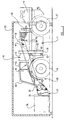
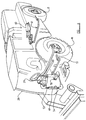
load handling apparatus 10 comprises abody 11 at a rear end of which there is provided a power operated motive means which in this embodiment is an engine 14 which in this example is longitudinally disposed but could be arranged transversely relative to a centre line A of theapparatus 10. Instead of an engine, a motor or some other suitable power operated motive means could alternatively be provided. The engine 14 is operative to provide driving torque tofront 16, or front andrear drive wheels - Mounted on the
body 11 is a telescopicallyextendable loader arm 18. Theloader arm 18 is arranged at one side of thebody 11 as can be seen best in figure 3, and is mounted adjacent afirst end 19 on thebody 11 for upward and downward movement about a generally horizontal axis B. At a secondopposite end 20 of theloader arm 18 there is provided aloading implement 21 which in this example is a pair ofloading forks carriage 24, but could be an alternative kind of loading implement such as for example only, a loading bucket. - The
loader arm 18 may be telescopically extended by any desired means such as one or more fluid operated actuators (not shown) between a refracted condition as seen in figure 1 and an extended condition shown in figure 2. - Mounted at a
front end 26 of thebody 11, there is an operator'scab 28 from which theapparatus 10 may be controlled. Within thecab 28 there is a steering control, such as asteering wheel 29, and the usual engine and actuator controls. - The
cab 28 is mounted on a mounting means 30 which comprises in this example a pair ofguides 31 which may be provided by re-entrant channels or the like, and thecab 28 includesfollowers 32 which may slide up and down in theguides 31. Thecab 28 may be lifted and lowered relative to thebody 11 by any desired powered means. In one arrangement, theguides 31 may each have a hydraulic or other fluid operated actuator therein, but preferably each guide has alead screw 33 or other threaded member, thefollowers 32 comprising female threaded parts which ride up and down thelead screws 33 as the lead screws are turned by some motive means. - In each case, the
cab 28 may be moved between a lower position shown in figure 1 and an upper position shown in figure 2 relative to thebody 11 and thus relative to thewheels cab 28. - It can be seen from figure 1 that a
top surface 34 of thecab 28 is the uppermost part of theapparatus 10 when thecab 28 is in its lower position and that overall theapparatus 10 is therefore sufficiently low to enable theapparatus 10 to be driven into height restricted area, such as within afreight container 35 as shown. Theloader arm 18 is still able to be operated within a limited lifting range and so theapparatus 10 may be used for handling e.g. pallettedloads 36 or other loads within thecontainer 35. - However, to enable an operator within the
cab 28 to have as clear a view as possible e.g. when operating theapparatus 10 with theloader arm 18 extended and elevated as seen in figure 2 , e.g. to load or unload thepalletted loads 36 onto thebed 37 of alorry 39, thecab 28 may be raised towards its upper position. - This provides a further advantage in that in the event that the
apparatus 10 is required to be driven into and/or operated in water or the like, which with thecab 28 in the lower position as indicated in figure 1 would be at a high level, thecab 28 may be raised so that no or a minimal amount of thecab 28 will be submerged in the water. Thus by ensuring that water sensitive components such as electronic controls, instrumentation, radio and the like are at as high a possible position in thecab 28, these may be protected from water damage. - The
loader arm 18 may be raised and lowered about axis B using conventional lifting and lowering technology. For example as shown, there is provided alifting actuator 40 which may be actuated by hydraulic fluid provided by the hydraulic pump, and theloading implement 21, or more importantly a load carried thereby, may be maintained in a substantially level orientation by fluid in a compensatingactuator 41 being exchanged with fluid of a tippingactuator 42 as theloader arm 18 is lifted and lowered. - Driving torque is transmitted from the engine 14 to the
ground wheels apparatus 10. The gearbox includes a pair of output shafts which are coupled via universal joints etc. torespective front 46 and rear 47 axles on which thedrive wheels front wheels 16 ofaxle 46 to be disconnected from the drive train whilst drive to therear wheels 17 ofaxle 47 is maintained, such disconnection means comprising a clutch or the like. Thus theapparatus 10 may be driven by two or four wheels as desired. - The
apparatus 10 is capable of being steered either using thefront wheels 16 alone, or in combination with therear wheels 17. To achieve this each of thewheels respective axles - In the case of the
front wheels 16, there is a mechanical connection between thefront wheels 16 and thesteering wheel 29 which includes atelescopic arrangement 49 to enable the mechanical connection to be maintained as thecab 28 is lifted and lowered. Otherwise movements of thesteering wheel 29 are transmitted to thefront wheels 16 via asteering box 50 andsteering swivel 51. Thetelescopic arrangement 49 includes asplined shaft 53 and correspondingly splined receivingmember 54, which splines remain in engagement as theshaft 53 telescopes inwardly and outwardly of the receivingmember 54 in response to downward and upward movement of thecab 28, - Steering is power assisted, there being a fluid (hydraulic) operated
actuator 55 to achieve this. - In the case of the
rear wheels 17, these are steered by means of a hydraulic actuator 60 (or actuators) which is coupled to therear wheels 17 via arelay lever system 61. The assistingactuator 55 for thefront wheels 16 is coupled operationally to the rearwheel steer actuator 60. For example both may be contained within a common hydraulic circuit in which fluid expelled from thefront wheel 16steer assisting actuator 55 drives the rearwheel steer actuator 60 whereby the twoactuators - From figure 3 it may be appreciated that the front 16 and rear 17 wheels may be operated in so called crab mode in which the front 16 and rear 17 wheels are operated in unison and turn in the same direction, or alternatively so called cramp mode in which the front 16 and
rear wheels 17 operate in unison but turn in opposite directions. Change over between four wheel steer in cramp and crab modes may be achieved by a hydraulic change over valve, which may also alternatively enable therear wheels 17 to be locked in a straight ahead set position so that two wheel steering using thefront wheels 16 only may be performed e.g. for on-road use. - The hydraulic change over valve may be controlled using an electronic control system which may incorporate proximity sensors or the like to determine at least when the
rear wheels 17 are in their straight ahead positions. - The electronic control system may be adapted only to allow four wheel steering when the
apparatus 10 is travelling over the ground below a predetermined set speed and may prevent change over between two and four wheel steering modes while theapparatus 10 is in motion. - Steering may otherwise be controlled as desired.
- The engine 14 may include a
cooling unit 65 which may be operative to cool the engine 14 and/or the hydraulic fluid used by the various actuators. Conveniently the coolingunit 65 is located longitudinally of theapparatus 10 between the engine 14 and theloader arm 18. - It will be appreciated from figure 1 that manoeuvrability of the
apparatus 10 within afreight container 35 is restricted. Often it will not be possible to handlepalletted loads 36 at both sides of thecontainer 35 by manoeuvring theapparatus 10. - Referring to figure 4 it can be seen that the loading implement 21 i.e. the
forks carriage 24 relative to theloader arm 18 so that a first pallet 36a may be handled in one corner of thecontainer 35 with theforks second pallet 36b may be handled in an opposite corner of thecontainer 35 with theforks -
Such carriage 24 sideways movement may be achieved by means of an actuator, or a lead screw or other threaded member which is rotated. - Furthermore, for added manoeuvrability, where the loading implement 21 comprises a pair of
forks forks carriage 24 to vary the spacing between them. This may most conveniently be achieved by means of a threaded member which is threaded oppositely along different regions thereof, with each of theforks forks - However adjustment of the spacing between the
forks - Referring now particularly to figure 5 the suspension arrangement of the
apparatus 10 is shown. - The front 46 and rear axles 47 (not shown in figure 5 for clarity) are suspended from the
body 11 of theapparatus 10 by respective non-reactive suspensions. Throughout this specification, by "non-reactive" we mean that the vertical load on the respectiveground engaging wheels - The suspension for the
front axle 46 comprises at each side of theapparatus 10, an upper leadinglink 68 which is connected at oneend 69 at a first position to thefront axle 46, and at anopposite end 71 to thebody 11, and a lower leadinglink 72 which is connected at one end at a second position 73 to the front axle, and at an opposite end 74 to thebody 11, thefirst position 69 being above the second position 73 and the points of connection of theupper links 68 to thebody 11 being above the points of connection of thelower links 72 to thebody 11. - The
front axle 46 further is located by means of aPanhard rod 75 which stabilises the front axle, provides reaction to the steering mechanism and affects roll steer and bump steer characteristics. -
Front axle 46 movement relative to thebody 11 is damped by dampingmembers 76 which in this example comprise hydropneumatic springs the resistance of which is controlled as a function of the level of theaxle 46 at the respective axle end, relative to thebody 11. This is achieved in this example by utilising a level sensing means comprising a fluid filledcylinder 78 which is coupled between thebody 11 andaxle 46. The sensing means 78 controls the flow of hydraulic fluid to and from the hydropneumatic springs 76, which fluid is separated from a gas chamber therein by a suitable diaphragm. The hydraulic pressure in thesprings 76 controls the degree of pneumatic damping provided by thesprings 76, so that the greater the displacement of thefront axle 76 at a respective side of theapparatus 10 relative to thebody 11, the greater the damping provided. - Additionally, the hydropneumatic springs 76 may include mechanical damping elements such as mechanical springs and resilient end stops to enable the suspension to handle sudden and
large axle 46 displacements as may occur when theapparatus 10 is travelling over very rough ground. - The
rear axle 47 is suspended from the body by a similar non-reactive suspension arrangement, although instead of a pair of leadingsuspension links apparatus 10, alower pair 80,81 of trailing links are provided, which are pivotably connected at respective first ends 83,84 to theaxle 47, and at respective second ends 85,86 to thebody 11. An upper pair of links 88,89 is also provided but these are pivotably connected at respective first ends 90,91 to theaxle 47, but are pivotably connected to each other and to thebody 11 at respective second ends 93, so that the upper links 88,89 are in a generally "V" configuration. - Damping is again provided by a pair of
hydropneumatic springs 94,95 and a level sensing means 96,97 is provided at eachaxle 47 side to sense the displacement of theaxle 47 relative to thebody 11 at each side and to control the flow of hydraulic fluid to thesprings 94,95 to control the degree of damping provided thereby. - By virtue of the non-reactive suspension being provided for the front and
rear axles apparatus 10 is inherently able to manoeuvre on rough terrain and is able to travel at relatively fast speed on smoother terrain, such as on the road. - For rough terrain use, the
apparatus 10 will tend to be operated in four wheel drive mode, i.e. with driving torque being transmitted to all fourwheels apparatus 10 will tend to be operated in two wheel steer mode and in two wheel drive mode. - By virtue of the combination of the ability of the
apparatus 10 to be operated selectively in each of these driving modes, and the provision of acab 28 which can be raised and lowered and the provision of a loading implement comprising particularly loadingforks loader arm 18, can be adjusted, a load handling apparatus of great versatility is provided. - However various modifications may be made without departing from the scope of the invention.
- For example, although the
cab 28 is shown at afront end 26 of thebody 11 of theapparatus 10, thecab 28 may be provided more rearwards and may be provided more centrally than the position shown. - The engine 14 may be mounted more centrally of the
apparatus 10 and may be provided in a lower position than shown. - In another arrangement which is not intended for on-road use and thus need not comply with the appropriate legislation,
front wheel 16 steering may be effected by solely hydraulic means such as described for therear wheels 17, or otherwise. Alternatively theapparatus 10 may be adapted forrear wheel 17 steering on the road so that the mechanical steering connection required to comply with highway legislation, may be to therear wheels 17 rather than thefront wheels 16. - Instead of the
cab 28 being movable up and down on a generally upright mounting means 30, thecab 28 may be movable up and down on a linkage arrangement. - It will be appreciated that although an
apparatus 10 having each of the features of - a) a
cab 28 which can be raised and lowered; - b) a combination of mechanical front wheel and power driven rear wheel steering;
- c) non-reactive suspension for one or both of the front and rear axles;
- d) relatively transversely adjustable loading forks; has been described, the advantages of these features may be individually realised on an
-
- Although the invention has been described with particular reference to a wheeled
apparatus having front 16 andrear wheels 17, the invention may be applied to a load handling apparatus comprising half or full tracks although such apparatus may not be as able as a fully wheeled vehicle to travel at relatively fast speed e.g. on the road. - The features disclosed in the foregoing description, or the following claims, or the accompanying drawings, expressed in their specific forms or in terms of a means for performing the disclosed function, or a method or process for attaining the disclosed result, as appropriate, may, separately, or in any combination of such features, be utilised for realising the invention in diverse forms thereof.
Claims (11)
- A load handling apparatus (10) including a body (11), a power operated motive means (14), a front axle (46) and a rear axle (47), the axles (46, 47) each carrying ground engaging means (16, 17) on which the apparatus (10) may move over the ground, at least one loader arm (18) supported at or adjacent one end (19) on the body (11) for movement about a generally horizontal axis (B), the loader arm (18) being adapted to carry a loading implement (21) at or adjacent a second end (20) thereof, the apparatus (10) further including an operator's cab (28), characterised in that means (30-33) are provided to move the cab (28) generally upwardly and downwardly between upper and lower positions relative to the ground engaging means (16, 17).
- An apparatus (10) according to claim 1 characterised in that the operator's cab is provided at or adjacent a front end of the body where the body provides a mounting means (30) on which the operator's cab (28) is carried for movement upwardly and downwardly whereby the operator's cab (28) is moveable upwardly and downwardly relative to the body (11) of the apparatus (10), the mounting means (30) comprising a guide means (31) and the operator's cab (28) comprising a follower means (32), there being actuator means (33) to move the follower means (32) relative to the guide means (31).
- An apparatus (10) according to claims 1 or claim 2 characterised in that the loader arm (18) extends forwardly of the operator's cab (28) and the generally horizontal axis (B) about which the loader arm (18) moves, is located rearwardly of the operator's cab (28) at or adjacent one side of the body (11), and the operator's cab (28) is located generally at an opposite side of the body (11), the generally horizontal axis (B) about which the loader arm (18)moves, being located above the level of the ground engaging means (16, 17).
- An apparatus (10) according to any one of the preceding claims characterised in that the front and rear axles (46, 47) are steerable and means are provided to lock one of the front and rear axles (46, 47) in a set position so as to achieve single axle steering only when required with a single fully steerable ground engaging means (16, 17), and wherein the fully steerable ground engaging means (16, 17) is steered by means of a mechanical connection (49, 50, 51) between a steering control operated from within the operator's cab (28) and the ground engaging means (16, 17), the mechanical connection (49, 50, 51) includes a telescopic assembly (49) whereby the mechanical connection is retained as the operator's cab (28) is lifted and lowered.
- An apparatus (10) according to any one of the preceding claims characterised in that the loading implement (21) is mounted at or adjacent the second end (20) of the loader arm (18) on a carriage (24) by means of which the loading implement (21) is movable in a transverse direction relative to the loader arm (18), the loading implement comprising pair of loading forks (22, 23), the forks being movable relative to each other in a transverse direction, the carriage (24) including a threaded member which has oppositely male threaded regions each carrying a respective female threaded member on which one of the loading forks (22, 23) is mounted, and there being means to rotate the male threaded member.
- An apparatus (10) according to any one of the preceding claims characterised in that at least one of the front and rear axles (46, 47) which carries ground engaging means (16, 17) which in use transmit driving torque to the ground, is suspended from the body (11) by means of a non-reactive suspension in which there is no significant change in the vertical loading on the ground engaging means (16, 17) in response to changes in the driving torque applied thereto.
- An apparatus (10) according to claim 6 characterised in that the non-reactive suspension comprises a pair of links (68, 72) at either side of the body (11), one link (68) of each pair being above the other (72) relative to the ground, the upper link (68) of each pair being pivotally connected at a first end (69) relative to the body (11) and at a second end to the axle (46, 47) at a first position and the lower link (72) of each pair being pivotally connected at a first end relative to the body (11) and at a second end to the axle (46, 47) at a second position (73), the second positions (73) each being below their respective first positions.
- An apparatus (10) according to claims 6 or claim 7 characterised in that a level sensing means (78) is provided at each side of the apparatus (10), for the or each axle (46, 47) which is suspended from the body by non-reactive suspension means, the level sensing means (78) in use sensing changes in the distance between the axle (46, 47) and the body (11) at the respective sides caused by changes in the ground surface over which the apparatus (10) travels, and there being a height regulating means (76) for each level sensing means (78) which is responsive to the respective level sensing means (78) to adjust the distance between the axle (46, 47) and the body (11) to return the axle (46, 47) at the respective side of the apparatus (10) to a datum position relative to the body (11).
- A load handling apparatus (10) including a body (11), a power operated motive means (14), a front axle (46) and a rear axle (47), the axles (46, 47) each carrying ground engaging means (16, 17) on which the apparatus (10) may move over the ground, at least one loader arm (18) supported at or adjacent one end on the body (11) for movement about a generally horizontal axis (B), the loader arm (18) being adapted to carry a loading implement (21) at or adjacent a second end thereof, the apparatus (10) further including an operator's cab (28), characterised in that the front and rear axles (46, 47) are steerable and means are provided to lock one of the front and rear axles (46, 47) in a set position so as to achieve single axle steering only when required with a single fully steerable ground engaging means (16, 17), the fully steerable ground engaging means (16, 17) being steerable by means of a mechanical connection (49, 50, 51) between a steering control operated from within the operator's cab (28) and the ground engaging means (16, 17) and there being power means provided to assist steering of the fully steerable ground engaging means (16, 17), the axle (46, 47) which can be locked in a set position being steerable by power means, and the power steering means of the lockable ground engaging means (16, 17) being operable in concert with the power assisted means which assist steering of the fully steerable ground engaging means (16, 17).
- A load handling apparatus (10) including a body (11), a power operated motive means (14), a front axle (46) and a rear axle (47), the axles (46, 47) each carrying ground engaging means (16, 17) on which the apparatus (11) may move over the ground, at least one loader arm (18) supported at or adjacent one end on the body (11) for movement about a generally horizontal axis (B), the loader arm (18) being adapted to carry a loading implement (21) at or adjacent a second end thereof, the apparatus (10) further including an operator's cab (28), characterised in that the loading implement (21) includes a pair of forks (22, 23) and the forks (22, 23) are movable relative to each in a transverse direction.
- A load handling apparatus (10) including a body (11), a power operated motive means (14), a front axle (46) and a rear axle (47), the axles (46, 47) each carrying ground engaging means (16, 17) on which the apparatus (10) may move over the ground, at least one loader arm (18) supported at or adjacent one end on the body (11) for movement about a generally horizontal axis (B), the loader arm (18) being adapted to carry a loading implement (21) at or adjacent a second end thereof, the apparatus (10) further including an operator's cab (28), characterised in that at least one of the front and rear axles (46, 47) which carries ground engaging means (16, 17) which in use transmit driving torque to the ground, is suspended from the body (11) by means of a non-reactive suspension in which there is no significant change in the vertical loading on the ground engaging means (16, 17) in response to changes in the driving torque applied thereto.
Applications Claiming Priority (2)
| Application Number | Priority Date | Filing Date | Title |
|---|---|---|---|
| GB9816144A GB2339761A (en) | 1998-07-25 | 1998-07-25 | Load handling apparatus |
| GB9816144 | 1998-07-25 |
Publications (3)
| Publication Number | Publication Date |
|---|---|
| EP0976878A2 true EP0976878A2 (en) | 2000-02-02 |
| EP0976878A3 EP0976878A3 (en) | 2000-04-12 |
| EP0976878B1 EP0976878B1 (en) | 2003-11-12 |
Family
ID=10836099
Family Applications (1)
| Application Number | Title | Priority Date | Filing Date |
|---|---|---|---|
| EP99113846A Expired - Lifetime EP0976878B1 (en) | 1998-07-25 | 1999-07-15 | Load handling apparatus |
Country Status (4)
| Country | Link |
|---|---|
| EP (1) | EP0976878B1 (en) |
| CA (1) | CA2278948A1 (en) |
| DE (1) | DE69912693D1 (en) |
| GB (1) | GB2339761A (en) |
Cited By (5)
| Publication number | Priority date | Publication date | Assignee | Title |
|---|---|---|---|---|
| EP1405954A1 (en) * | 2002-10-01 | 2004-04-07 | J.C. Bamford Excavators Limited | Excavating and loading machine |
| CN102155029A (en) * | 2010-02-11 | 2011-08-17 | J.C.班福德挖掘机有限公司 | Working machine |
| US8041492B2 (en) * | 2006-10-31 | 2011-10-18 | Clark Equipment Company | Engine load management for power machines |
| US9045882B2 (en) | 2010-02-11 | 2015-06-02 | J.C. Bamford Excavators Limited | Working machine |
| JP2022093121A (en) * | 2020-12-11 | 2022-06-23 | 株式会社クボタ | Work vehicle |
Families Citing this family (3)
| Publication number | Priority date | Publication date | Assignee | Title |
|---|---|---|---|---|
| GB2387822B (en) | 2000-02-01 | 2004-03-24 | Bamford Excavators Ltd | Axle |
| GB0002154D0 (en) * | 2000-02-01 | 2000-03-22 | Bamford Excavators Ltd | Working apparatus |
| GB2470739A (en) * | 2009-06-02 | 2010-12-08 | Redrock Engineering Ltd | Telehandler vehicle having improved drive train layout |
Family Cites Families (21)
| Publication number | Priority date | Publication date | Assignee | Title |
|---|---|---|---|---|
| CH519291A (en) * | 1968-10-07 | 1972-02-29 | Lely Nv C Van Der | Self-propelled agricultural machine that can be used as a tractor |
| GB1529302A (en) * | 1974-10-05 | 1978-10-18 | Coles Cranes Ltd | Steering arrangements for mobile cranes |
| GB1601616A (en) * | 1978-04-07 | 1981-11-04 | Schopf Masch | Load carrying vehicles |
| GB2078634B (en) * | 1980-06-30 | 1984-04-26 | Claas Ohg | Agricultural multi-purpose vehicle |
| US4381166A (en) * | 1980-10-27 | 1983-04-26 | Smart Robert L | Fork unit having adjustable forks |
| DE3115398A1 (en) * | 1981-04-16 | 1982-12-16 | Ernst 7326 Heiningen Weichel | Self-propelled implement carrier |
| CA1287147C (en) * | 1985-10-24 | 1991-07-30 | Hiromu Fujimoto | Tractor equipped with working implements |
| US4688982A (en) * | 1986-08-01 | 1987-08-25 | Smart Robert L | Motorized operator unit for manually adjustable fork mechanism |
| US4986721A (en) * | 1989-08-17 | 1991-01-22 | Eagle-Picher Industries, Inc. | Extendable boom fork lift vehicle |
| GB2252278B (en) * | 1990-07-28 | 1994-03-09 | Jcb Landpower Ltd | Vehicle |
| GB2263451B (en) * | 1992-01-17 | 1995-05-17 | D J Ind Ltd | Vehicle with front and rear steering |
| GB2292929A (en) * | 1992-06-30 | 1996-03-13 | Caterpillar Inc | Material Handling Machine |
| GB9223840D0 (en) * | 1992-11-13 | 1993-01-06 | Fermec Mfg Ltd | Vehicle |
| GB2294246B (en) * | 1993-06-18 | 1997-02-05 | Australian Defence Ind Ltd | Engineering vehicle with lockable fluid suspension |
| US5427195A (en) * | 1994-05-04 | 1995-06-27 | Int. Silvatech Ltd. | Hydraulic drive and steering systems for a vehicle |
| GB9423669D0 (en) * | 1994-11-23 | 1995-01-11 | Dowler David | A vehicle |
| JPH11500800A (en) * | 1995-12-08 | 1999-01-19 | カール シェフ ゲーエムベーハー ウント コンパニ マシーネンファブリク | Bucket loader with large loading height |
| GB2311967A (en) * | 1996-04-10 | 1997-10-15 | Bateman Engineering Ltd | A variable-track, four wheel steering agricultural vehicle with active suspension |
| DE69704589T2 (en) * | 1996-06-25 | 2001-08-09 | Bamford Excavators Ltd | Handling vehicle for material |
| GB9706859D0 (en) * | 1997-04-04 | 1997-05-21 | Bamford Excavators Ltd | Material handling implement |
| DE29715920U1 (en) * | 1997-09-04 | 1997-10-30 | Sennebogen Erich | Work machine |
-
1998
- 1998-07-25 GB GB9816144A patent/GB2339761A/en not_active Withdrawn
-
1999
- 1999-07-15 EP EP99113846A patent/EP0976878B1/en not_active Expired - Lifetime
- 1999-07-15 DE DE69912693T patent/DE69912693D1/en not_active Expired - Lifetime
- 1999-07-23 CA CA002278948A patent/CA2278948A1/en not_active Abandoned
Non-Patent Citations (1)
| Title |
|---|
| None |
Cited By (8)
| Publication number | Priority date | Publication date | Assignee | Title |
|---|---|---|---|---|
| EP1405954A1 (en) * | 2002-10-01 | 2004-04-07 | J.C. Bamford Excavators Limited | Excavating and loading machine |
| US6920708B2 (en) | 2002-10-01 | 2005-07-26 | J. C. Bamford Excavators Limited | Excavating and loading machine |
| US8041492B2 (en) * | 2006-10-31 | 2011-10-18 | Clark Equipment Company | Engine load management for power machines |
| CN102155029A (en) * | 2010-02-11 | 2011-08-17 | J.C.班福德挖掘机有限公司 | Working machine |
| EP2357285A1 (en) * | 2010-02-11 | 2011-08-17 | J.C. Bamford Excavators Limited | Cabin for a skid-steer loader |
| US9045882B2 (en) | 2010-02-11 | 2015-06-02 | J.C. Bamford Excavators Limited | Working machine |
| CN102155029B (en) * | 2010-02-11 | 2015-10-14 | J.C.班福德挖掘机有限公司 | Working machine |
| JP2022093121A (en) * | 2020-12-11 | 2022-06-23 | 株式会社クボタ | Work vehicle |
Also Published As
| Publication number | Publication date |
|---|---|
| EP0976878B1 (en) | 2003-11-12 |
| GB2339761A (en) | 2000-02-09 |
| DE69912693D1 (en) | 2003-12-18 |
| EP0976878A3 (en) | 2000-04-12 |
| CA2278948A1 (en) | 2000-01-25 |
| GB9816144D0 (en) | 1998-09-23 |
Similar Documents
| Publication | Publication Date | Title |
|---|---|---|
| US6752403B2 (en) | Working apparatus | |
| US11111649B2 (en) | Working machine | |
| EP1580100B1 (en) | Vehicle support system | |
| US3007590A (en) | Shovel loaders | |
| CA3010648C (en) | Telehandler with cantilever boom mounting | |
| WO2006023011A2 (en) | Steerable bogie | |
| US9994105B2 (en) | Working machine | |
| US20160122972A1 (en) | Undercarriage for a Working Machine | |
| GB2531768A (en) | An Undercarriage for a Working Machine | |
| EP0976878B1 (en) | Load handling apparatus | |
| EP1437324B1 (en) | Working apparatus | |
| US4411329A (en) | Vehicle with multi-directional movement capabilities | |
| GB2311967A (en) | A variable-track, four wheel steering agricultural vehicle with active suspension | |
| EP1153772B1 (en) | Load carrying machine | |
| GB2264689A (en) | Load handling truck | |
| CN116635591A (en) | Work machine | |
| US20230340756A1 (en) | Work machine | |
| USRE29197E (en) | Shovel loaders | |
| GB2383984A (en) | Articulated lift truck | |
| US4201273A (en) | Vehicle axle suspension system | |
| JPH0860708A (en) | Civil engineering car | |
| JPH115423A (en) | Car body rolling device for tractor | |
| GB2399062A (en) | Articulated lift truck | |
| JPH0344002B2 (en) |
Legal Events
| Date | Code | Title | Description |
|---|---|---|---|
| PUAI | Public reference made under article 153(3) epc to a published international application that has entered the european phase |
Free format text: ORIGINAL CODE: 0009012 |
|
| AK | Designated contracting states |
Kind code of ref document: A2 Designated state(s): DE ES FR GB IT SE |
|
| AX | Request for extension of the european patent |
Free format text: AL;LT;LV;MK;RO;SI |
|
| PUAL | Search report despatched |
Free format text: ORIGINAL CODE: 0009013 |
|
| RIC1 | Information provided on ipc code assigned before grant |
Free format text: 7E 02F 9/16 A, 7A 01B 51/02 B, 7B 62D 7/15 B |
|
| AK | Designated contracting states |
Kind code of ref document: A3 Designated state(s): AT BE CH CY DE DK ES FI FR GB GR IE IT LI LU MC NL PT SE |
|
| AX | Request for extension of the european patent |
Free format text: AL;LT;LV;MK;RO;SI |
|
| 17P | Request for examination filed |
Effective date: 20000927 |
|
| AKX | Designation fees paid |
Free format text: DE ES FR GB IT SE |
|
| 17Q | First examination report despatched |
Effective date: 20020211 |
|
| GRAH | Despatch of communication of intention to grant a patent |
Free format text: ORIGINAL CODE: EPIDOS IGRA |
|
| GRAS | Grant fee paid |
Free format text: ORIGINAL CODE: EPIDOSNIGR3 |
|
| GRAA | (expected) grant |
Free format text: ORIGINAL CODE: 0009210 |
|
| AK | Designated contracting states |
Kind code of ref document: B1 Designated state(s): DE ES FR GB IT SE |
|
| REG | Reference to a national code |
Ref country code: GB Ref legal event code: FG4D |
|
| REF | Corresponds to: |
Ref document number: 69912693 Country of ref document: DE Date of ref document: 20031218 Kind code of ref document: P |
|
| PG25 | Lapsed in a contracting state [announced via postgrant information from national office to epo] |
Ref country code: SE Free format text: LAPSE BECAUSE OF FAILURE TO SUBMIT A TRANSLATION OF THE DESCRIPTION OR TO PAY THE FEE WITHIN THE PRESCRIBED TIME-LIMIT Effective date: 20040212 |
|
| PG25 | Lapsed in a contracting state [announced via postgrant information from national office to epo] |
Ref country code: DE Free format text: LAPSE BECAUSE OF FAILURE TO SUBMIT A TRANSLATION OF THE DESCRIPTION OR TO PAY THE FEE WITHIN THE PRESCRIBED TIME-LIMIT Effective date: 20040213 |
|
| PG25 | Lapsed in a contracting state [announced via postgrant information from national office to epo] |
Ref country code: ES Free format text: LAPSE BECAUSE OF FAILURE TO SUBMIT A TRANSLATION OF THE DESCRIPTION OR TO PAY THE FEE WITHIN THE PRESCRIBED TIME-LIMIT Effective date: 20040223 |
|
| ET | Fr: translation filed | ||
| PLBE | No opposition filed within time limit |
Free format text: ORIGINAL CODE: 0009261 |
|
| STAA | Information on the status of an ep patent application or granted ep patent |
Free format text: STATUS: NO OPPOSITION FILED WITHIN TIME LIMIT |
|
| 26N | No opposition filed |
Effective date: 20040813 |
|
| REG | Reference to a national code |
Ref country code: FR Ref legal event code: PLFP Year of fee payment: 18 |
|
| REG | Reference to a national code |
Ref country code: FR Ref legal event code: PLFP Year of fee payment: 19 |
|
| REG | Reference to a national code |
Ref country code: FR Ref legal event code: PLFP Year of fee payment: 20 |
|
| PGFP | Annual fee paid to national office [announced via postgrant information from national office to epo] |
Ref country code: IT Payment date: 20180719 Year of fee payment: 20 Ref country code: FR Payment date: 20180725 Year of fee payment: 20 |
|
| PGFP | Annual fee paid to national office [announced via postgrant information from national office to epo] |
Ref country code: GB Payment date: 20180717 Year of fee payment: 20 |
|
| REG | Reference to a national code |
Ref country code: GB Ref legal event code: PE20 Expiry date: 20190714 |
|
| PG25 | Lapsed in a contracting state [announced via postgrant information from national office to epo] |
Ref country code: GB Free format text: LAPSE BECAUSE OF EXPIRATION OF PROTECTION Effective date: 20190714 |