EP0976641B1 - Zusammenbau einer Bedieneinheit mit einer Kraftfahrzeuglenksäule - Google Patents
Zusammenbau einer Bedieneinheit mit einer Kraftfahrzeuglenksäule Download PDFInfo
- Publication number
- EP0976641B1 EP0976641B1 EP99401863A EP99401863A EP0976641B1 EP 0976641 B1 EP0976641 B1 EP 0976641B1 EP 99401863 A EP99401863 A EP 99401863A EP 99401863 A EP99401863 A EP 99401863A EP 0976641 B1 EP0976641 B1 EP 0976641B1
- Authority
- EP
- European Patent Office
- Prior art keywords
- ring
- tube body
- bearing
- assembly
- tube
- Prior art date
- Legal status (The legal status is an assumption and is not a legal conclusion. Google has not performed a legal analysis and makes no representation as to the accuracy of the status listed.)
- Expired - Lifetime
Links
- 229920003023 plastic Polymers 0.000 claims description 18
- 239000004033 plastic Substances 0.000 claims description 18
- 238000005192 partition Methods 0.000 claims description 7
- 238000002788 crimping Methods 0.000 claims description 6
- 238000000034 method Methods 0.000 claims description 6
- 230000003014 reinforcing effect Effects 0.000 claims description 4
- 208000031968 Cadaver Diseases 0.000 description 31
- 239000000872 buffer Substances 0.000 description 13
- 210000002105 tongue Anatomy 0.000 description 10
- 210000002445 nipple Anatomy 0.000 description 7
- 230000002787 reinforcement Effects 0.000 description 6
- 238000004519 manufacturing process Methods 0.000 description 5
- 230000035515 penetration Effects 0.000 description 4
- 238000010521 absorption reaction Methods 0.000 description 2
- 239000000463 material Substances 0.000 description 2
- 230000035939 shock Effects 0.000 description 2
- 230000000712 assembly Effects 0.000 description 1
- 238000000429 assembly Methods 0.000 description 1
- 238000003825 pressing Methods 0.000 description 1
- 230000007306 turnover Effects 0.000 description 1
- 238000003466 welding Methods 0.000 description 1
Images


Classifications
-
- B—PERFORMING OPERATIONS; TRANSPORTING
- B62—LAND VEHICLES FOR TRAVELLING OTHERWISE THAN ON RAILS
- B62D—MOTOR VEHICLES; TRAILERS
- B62D1/00—Steering controls, i.e. means for initiating a change of direction of the vehicle
- B62D1/02—Steering controls, i.e. means for initiating a change of direction of the vehicle vehicle-mounted
- B62D1/16—Steering columns
-
- F—MECHANICAL ENGINEERING; LIGHTING; HEATING; WEAPONS; BLASTING
- F16—ENGINEERING ELEMENTS AND UNITS; GENERAL MEASURES FOR PRODUCING AND MAINTAINING EFFECTIVE FUNCTIONING OF MACHINES OR INSTALLATIONS; THERMAL INSULATION IN GENERAL
- F16C—SHAFTS; FLEXIBLE SHAFTS; ELEMENTS OR CRANKSHAFT MECHANISMS; ROTARY BODIES OTHER THAN GEARING ELEMENTS; BEARINGS
- F16C35/00—Rigid support of bearing units; Housings, e.g. caps, covers
- F16C35/04—Rigid support of bearing units; Housings, e.g. caps, covers in the case of ball or roller bearings
- F16C35/06—Mounting or dismounting of ball or roller bearings; Fixing them onto shaft or in housing
- F16C35/07—Fixing them on the shaft or housing with interposition of an element
- F16C35/077—Fixing them on the shaft or housing with interposition of an element between housing and outer race ring
-
- F—MECHANICAL ENGINEERING; LIGHTING; HEATING; WEAPONS; BLASTING
- F16—ENGINEERING ELEMENTS AND UNITS; GENERAL MEASURES FOR PRODUCING AND MAINTAINING EFFECTIVE FUNCTIONING OF MACHINES OR INSTALLATIONS; THERMAL INSULATION IN GENERAL
- F16C—SHAFTS; FLEXIBLE SHAFTS; ELEMENTS OR CRANKSHAFT MECHANISMS; ROTARY BODIES OTHER THAN GEARING ELEMENTS; BEARINGS
- F16C2326/00—Articles relating to transporting
- F16C2326/20—Land vehicles
- F16C2326/24—Steering systems, e.g. steering rods or columns
Definitions
- the present invention relates to assembly a set of commands with a column of motor vehicle steering, as defined in the preamble of claim 1 and describes in document DE-U-7807568.
- the steering column has a steering, which is mounted in a tube-body.
- the tube-body is arranged in at least one support element, which is fixed to the structure of the vehicle. All is located under the steering wheel, and it is mounted on the tube-body.
- the purpose of the present invention is to provide an assembly, which avoids the disadvantages described above; and which allows to realize directly mounting the control assembly in the tube-body, that is to say without any adjustment in chain manufacturing, while obtaining the position exact angular requested.
- Assembling a set of controls with a motor vehicle steering column according to the invention is constituted by a column of steering, which has a mounted steering shaft free to rotate in a body tube using two bearings.
- a flywheel is connected to the shaft of direction, and the set of controls is arranged under the steering wheel and is mounted on the body tube.
- said tube-body is arranged in at least one element support fixed to the structure of the motor vehicle.
- the bearing which is located on the side of the steering wheel, is disposed between the body tube and the steering shaft.
- Said assembly comprises a material ring plastic, which is arranged between said bearing and the tube-body.
- Said ring comprises in the direction axial a central portion and an outer portion. The central portion receives the bearing, and the outer portion is the axial extension of the central portion, the outer portion being located on the side of the control unit and the steering wheel.
- Said outer portion is provided with at least a shape, which is correctly positioned angularly with respect to the interface between one support elements and the structure of the vehicle.
- Said shape is arranged and sized for interpenetrate with a conjugate form, which is arranged in the control unit, so that this set of controls is mounted on the tube-body at the exact angular position desired by relationship to the interface between one of the support elements and the structure of the vehicle.
- the inner portion of the ring is provided with radial reinforcing ribs, which are arranged on the internal face of said portion interior.
- the ring has at least one form of assembly, which is constituted by a notch, which cooperates with a nipple fitted in the set of controls.
- the ring has at least one form of assembly, which is constituted by a nipple, which cooperates with a notch fitted in the set of controls.
- the tube-body is arranged in two support elements attached to the vehicle structure.
- Assembling a set of controls with a motor vehicle steering column thus has the advantage of allowing the mounting in the tube-body without any adjustment, everything ensuring a correct angular position by relative to the chosen reference, which can be the axis or the interface with between an element support and structure of the vehicle.
- the plastic ring due to its material allows to adapt to the tolerances of manufacture of the tube-body.
- This assembly also has other advantages.
- the internal buffers which are made on the tube-body, positively stop the ring, due to interference of the ring with the stops internal; and this up to a known effort, which corresponds to normal use of the column.
- the ring In case of shock, when the forces transmitted to the turnover are very important and greater than the previous known effort, the ring has the possibility to pass over the bumpers.
- the sliding of the ring on the stops is relatively constant, and allows absorption of energy controlled during the impact.
- the axial position of the mounting of the ring on the tube may vary without affecting subsequent operation energy absorption in case of shock.
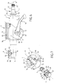
- the invention relates to a column of motor vehicle management, all of which located near the driver's steering wheel is shown in Figure 6.
- the steering column has a steering shaft 1, which is mounted in a body tube 3 along axis 11 of the steering shaft 1.
- the steering shaft 1 is mounted to rotate freely in the tube-body 3 with respect to its axis 11. This mounting is carried out via two bearings 5 and 6.
- the bearing 5 is disposed between the body tube 3 and the steering shaft 1, and it is located on the steering wheel side.
- the tube-body 3 is provided with a reinforcement square 15, which is arranged inside a support element 7.
- the support element 7 consists of a base 86, which is provided at each of its two ends with a amount referenced 87 and 88.
- the support element 7 is connected to the structure 13 of the motor vehicle with an interface 85.
- the tube-body assembly 3 with its reinforcement square 15 is disposed inside the two uprights 87 and 88 of the support element 7. Said uprights are substantially parallel to the axis 11.
- the support element 8 is arranged on the side of the bearing 6, that is to say opposite of the steering wheel of the driver.
- the support element 8 consists of a base 91, which is provided with each of its two ends of an amount referenced 92 and 93.
- the support element 8 is connected to the structure 13 of the motor vehicle with an interface 90.
- the whole of the tube-body 3 is disposed at the interior of the two uprights 92 and 93 of the support element 8.
- the said amounts 92 and 93 are substantially parallel to the axis 11 of the shaft of direction 1.
- the invention can be applied to two types of steering columns: the steering columns fixed, and adjustable steering columns.
- the support elements 7 and 8 are rigidly connected to the entire tube-body 3. This can be by example by welding or any other means.
- the entire body-tube 3 is adjustable with respect to the support element 7 and with respect to the support element 8.
- the entire tube-body 3 is connected to the support element 8 by a hinge pin 94 substantially perpendicular to axis 11.
- the tube-body 3 with its reinforcement square 15 is connected to the support element 7 by an adjustment system in position relative to said support element 7.
- This position adjustment system is locked to the position chosen by a clamping device 9, along a clamping axis 12, which is substantially perpendicular to the axis 11 of the steering shaft 1.
- the clamping axis 12 passes through the reinforcement square 15 of the tube-body 3, and the two uprights 87 and 88 of the support element 7.
- the clamping device 9 is controlled by an operating assembly 10, which can be manual as in figure 6 or any other type such as a remote order.
- the device clamp 9 is put in the locked position or unlocked by the operating assembly 10.
- the clamping axis 12 can possibly cross the tube-body 3, which is not not necessarily equipped with a reinforcement square 15.
- the different elements making up the clamp 9 are mounted, either on a clamp rod clamping axis 12, or by any other means.
- the invention relates to an assembly shown in Figure 1, which is an exploded view in perspective of all of assembly.
- Assembly concerns the assembly of a set of controls 2 with a steering column of motor vehicle described above.
- the set of controls 2 is arranged under the driver's steering wheel 14.
- the steering wheel is connected to the end 21 of the steering shaft 1.
- the control assembly is mounted on the body tube 3, and it is thus located between the flywheel 14 and the tube-body 3.
- the assembly according to the invention comprises a plastic ring 4, which is arranged between the bearing 5 and the tube-body 3.
- the ring 4 comprises in the axial direction a central portion 30, an inner portion 31 and an outer portion 32.
- the central portion 30 receives the bearing 5, and the outer portion 32 is the axial extension of the central portion 30.
- the outer portion 32 is thus located on the side of the control assembly 2 and of the steering wheel 14.
- the outer portion 32 is provided with two forms referenced respectively 43 and 44, which are correctly positioned angularly by compared to the interface 85 or / and 90 located between the support element 7 and the support element respectively 8 with structure 13 of the vehicle automobile.
- Forms 43 and 44 are arranged and sized to interpenetrate with respectively a conjugate form referenced 73 and 74, which are arranged in the set of controls 2 ; so that this set of controls is mounted on the tube-body 3 at the exact angular position desired with respect to interface 85 or / and 90 between respectively one of the support elements 7 and 8 and the structure 13 of the vehicle.
- the plastic ring 4 has one side outer 33, an inner side face 34, and a outer side face 35.
- the ring 4 is provided with a partition 36 disposed between the portion central 30 and the inner portion 31.
- the bearing 5 has an inner ring 26 and a outer ring 27, the inner side face of which is referenced 28 and the outer side face is referenced 29.
- the bearing 5 is forcibly mounted in the ring 4 by engaging in the internal face 42 of the outer portion 32, and the bearing which forcibly engages in this internal face 42 comes lean against a bottom 41 of the partition 36.
- the partition 36 has an internal face 37 arranged so as to allow the steering shaft to pass freely 1. From plus, the inner portion 31 of the ring 4 is provided with radial reinforcing ribs 39 which are arranged on the internal face 38 of said portion interior 31.
- the ring 4 has two forms of assembly which consist of a notch 43 and 44. These notches 43 and 44 cooperate respectively with a nipple 73 and 74 which is arranged in all of commands 2.
- each of the notches has a shape substantially rectangular with respectively a bottom 45 and 46, and sides 47 and 48. These sides 47 and 48 are substantially parallel to the axis 11 and the notches 43 and 44 in the case shown are diametrically opposite.
- the set of controls 2 under the steering wheel 14 has a housing 70 sized so that it can come engage the tube-body 3.
- This housing 70 is equipped with two nipples referenced 73 and 74, these nipples having a vertex 75 and 76 respectively and sides 77 and 78.
- These nipples 73 and 74 are diametrically opposite and are sized to be able to fit exactly in notches 43 and 44 arranged in the outer portion 32 of the ring 4.
- the tube-body has at its end 52 a face internal 50 and an external face 51, and it ends at the end by an outer end face 53.
- the tube-body 3 is provided with two notches referenced 55 and 56 which are arranged at its end 52.
- the notches 55 and 56 have the same angular orientation and have a width and a depth greater than the width and depth of the notches corresponding 43 and 44 of the ring 4; in a way to ability to adjust angle of ring 4 during the mounting of said ring 4 in the tube-body 3.
- the plastic ring 4 is engaged in the tube-body 3 and it is axially blocked in the tube-body 3 between internal buffers 54 and crimps.
- the internal buffers 54 are even arranged on the internal face 50 of the tube-body 3, and the crimps are arranged at the end 52 of the tube-body 3.
- Each of the crimps is obtained by two grooves 61, which are parallel and of direction axial in order to produce a tongue 62, which is folded against the outer lateral face 29 of the bearing 5.
- each tongue 62 passes through an opening 49, which is arranged in the portion outer 32 of the ring 4.
- Each of the notches 55 and 56 has a shape substantially rectangular with respectively a bottom 57 and 58 and sides 59 and 60.
- the ring 4 is provided with two pins 63 and 64, which are arranged in the outer portion 32.
- the ring 4 is locked axially in the tube-body 3 between the internal buffers 54 and crimps.
- the internal buffers 54 are arranged on the face internal 50 of the tube-body 3, and the crimps are arranged at the end 52 of the tube-body 3.
- Each of the crimps is obtained by two grooves 61 which are parallel and axial direction to achieve a tongue 62, which is folded against the face lateral lateral 29 of the bearing 5.
- Each tongue 62 passes through an opening 49, which is fitted in the outer portion 32 of the ring 4.
- pins 63 and 64 are diametrically opposed or respectively a vertex 65 and 66 and sides 67 and 68, which are substantially parallel to the axis 11.
- Nipples 63 and 64 are sized to cooperate with notches referenced 79 and 80 respectively which are fitted in the set of controls 2.
- the control assembly 2 then has in its housing 70, two diametrically opposite notches 79 and 80 which have a background 81 and 82 respectively and sides 83 and 84.
Landscapes
- Engineering & Computer Science (AREA)
- General Engineering & Computer Science (AREA)
- Mechanical Engineering (AREA)
- Chemical & Material Sciences (AREA)
- Combustion & Propulsion (AREA)
- Transportation (AREA)
- Steering Controls (AREA)
Claims (11)
- Zusammenbau einer Bedieneinheit (2) mit einer Lenksäule eines Kraftfahrzeugs, wobei die Lenksäule in diesem Zusammenbau eine Lenkwelle (1) umfaßt, die mittels zweier Lager (5 und 6) in einem Rohrkörper (3) frei zur Drehung angebracht ist, ein Lenkrad (14) mit der Lenkwelle (1) verbunden ist und die Bedieneinheit (2) unter dem Lenkrad (14) vorgesehen ist und auf dem Rohrkörper (3) angebracht ist, der Rohrkörper (3) in wenigstens einem an dem Aufbau (13) des Kraftfahrzeugs befestigten Trägerelement (7) angeordnet ist, das Lager (5), das sich auf der Seite des Lenkrads (14) befindet, zwischen dem Rohrkörper (3) und der Lenkwelle (1) angeordnet ist, der Zusammenbau einen Ring (4) aus Kunststoff umfaßt, der zwischen dem Lager (5) und dem Rohrkörper (3) angeordnet ist, dadurch gekennzeichnet, daßder Ring (4) in der axialen Richtung einen zentralen Abschnitt (30) und einen äußeren Abschnitt (32) umfaßt, wobei der zentrale Abschnitt (30) das Lager (5) aufnimmt und der äußere Abschnitt (32) die axiale Verlängerung des zentralen Abschnitts (30) ist, wobei sich der äußere Abschnitt (32) auf der Seite der Bedieneinheit (2) und des Lenkrads (14) befindet;der äußere Abschnitt (32) mit wenigstens einer Form (43, 44 - 63, 64) versehen ist, die winkelmäßig korrekt in bezug auf die Grenzfläche (85, 90) zwischen dem einen der Trägerelemente (7, 8) und dem Aufbau des Fahrzeugs (13) positioniert ist;die Form (43, 44 - 63, 64) angeordnet und bemessen ist, um sich mit einer zugeordneten Form (73, 74 - 79, 80) zu durchdringen, die in der Bedieneinheit (2) angeordnet ist derart, daß diese Bedieneinheit (2) auf dem Rohrkörper (3) in der gewünschten exakten Winkelposition in bezug auf die Grenzfläche (85, 90) zwischen dem einen der Trägerelemente (7, 8) und dem Aufbau des Fahrzeugs (13) angebracht ist.
- Zusammenbau nach Anspruch 1, dadurch gekennzeichnet, daß der Ring (4) umfaßt:den zentralen Abschnitt (30), in dem das Lager (5) angebracht ist;den äußeren Abschnitt (32), der mit der Form (43, 44-63, 64) für den Zusammenbau mit der zugeordneten Form (73, 74 - 79, 80) der Bedieneinheit (2) versehen ist;einen inneren Abschnitt (31), der von dem zentralen Abschnitt (30) durch eine Zwischenwand (36) getrennt ist, wobei das Lager (5) zur Auflage gegen den Boden (41) der Zwischenwand (36) gelangt.
- Zusammenbau nach Anspruch 2, dadurch gekennzeichnet, daß der innere Abschnitt (31) des Rings (4) mit radialen Versteifungsrippen (39) versehen ist, die auf der Innenseite (38) des inneren Abschnitts (31) angeordnet sind.
- Zusammenbau nach einem beliebigen der vorhergehenden Ansprüche, dadurch gekennzeichnet, daß der Ring (4) wenigstens eine Zusammenbauform aufweist, die aus einem Einschnitt (43, 44) besteht, der mit einem Ansatz (73, 74) zusammenwirkt, der in der Bedieneinheit (2) angeordnet ist.
- Zusammenbau nach einem beliebigen der Ansprüche 1 bis 3, dadurch gekennzeichnet, daß der Ring (4) wenigstens eine Zusammenbauform aufweist, die aus einem Ansatz (63, 64) besteht, der mit einem Einschnitt (79, 80) zusammenwirkt, der in der Bedieneinheit (2) angeordnet ist.
- Zusammenbau nach einem beliebigen der vorhergehenden Ansprüche, dadurch gekennzeichnet, daß der Rohrkörper (3) in zwei Trägerelementen (7 und 8) angeordnet ist, die an dem Aufbau (13) des Fahrzeugs befestigt sind.
- Zusammenbau nach einem beliebigen der Ansprüche 1 bis 5, dadurch gekennzeichnet, daß:der Rohrkörper (3) angeordnet ist in:einem ersten Trägerelement (7), das aus einer Befestigungsfläche (86) besteht, die an jedem ihrer beiden Enden einen Stützschenkel (87, 88) aufweist, wobei der Rohrkörper (3) im Inneren der beiden Stützschenkel (87, 88) des Trägerelements (7) angeordnet ist, wobei die beiden Stützschenkel (87, 88) im wesentlichen parallel zur Achse (11) der Lenkwelle (1) sind;einem zweiten Trägerelement (8), das aus einer Befestigungsfläche (91) besteht, die an jedem ihrer beiden Enden einen Stützschenkel (92, 93) aufweist, wobei der Rohrkörper (3) im Inneren der beiden Stützschenkel (92, 93) des Trägerelements (8) angeordnet ist, wobei die Stützschenkel (92, 93) im wesentlichen parallel zur Achse (11) der Lenkwelle sind und der Rohrkörper (3) mit dem Trägerelement (8) mittels einer Drehachse (94) verbunden ist,der Rohrkörper (3) ein System zur Positionseinstellung in bezug auf das Trägerelement (7) aufweist, das in der gewählten Position durch eine Klemmvorrichtung (9) verriegelt ist, die eine Klemmachse (12) aufweist, die einen Versteifungsvierkant (15) des Rohrkörpers (3) und die beiden Stützschenkel (87) und (88) durchquert, wobei die Klemmvorrichtung (3) durch eine Betätigungseinheit (10) bedient wird.
- Zusammenbau nach einem der Ansprüche 6 oder 7, dadurch gekennzeichnet, daß:der Ring (4) mit zwei Einschnitten (43) und (44) versehen ist, die in dem äußeren Abschnitt (32) angeordnet sind;der Rohrkörper (3) mit zwei Einschnitten (55) und (56) versehen ist, die in seinem Ende (52) angeordnet sind; die Einschnitte (55) und (56) dieselbe Winkelorientierung aufweisen und eine größere Breite als die Breite der entsprechenden Einschnitte (43) und (44) des Rings (4) aufweisen; derart, daß eine Winkeleinstellung des Rings (4) zur Zeit der Anbringung des Rings (4) im Rohrkörper (3) ausgeführt werden kann;der Ring (4) axial im Rohrkörper (3) zwischen Innenanschlägen (54) und Bördelverbindungen verriegelt ist; die Innenanschläge (54) auf der Innenseite (50) des Rohrkörpers (3) angeordnet sind und die Bördelverbindungen am Ende (52) des Rohrkörpers (3) angeordnet sind; wobei jede der Bördelverbindungen durch zwei parallele und axiale Richtung aufweisenden Spalte (61) zur Ausführung einer Leiste (62) erhalten wird, die gegen die seitliche Außenseite (29) des Lagers (5) umgelegt ist, wobei jede Leiste (62) eine im äußeren Abschnitt (32) des Rings (4) angeordnete Öffnung (49) durchquert.
- Zusammenbau nach einem der Ansprüche 6 oder 7, dadurch gekennzeichnet, daß:der Ring (4) mit zwei Ansätzen (63) und (64) versehen ist, die im äußeren Abschnitt (32) angeordnet sind;der Ring (4) axial im Rohrkörper (3) zwischen Innenanschlägen (54) und Bördelverbindungen verriegelt ist; die Innenanschläge (54) auf der Innenseite (50) des Rohrkörpers (3) angeordnet sind und die Bördelverbindungen am Ende (52) des Rohrkörpers (3) angeordnet sind; wobei jede der Bördelverbindungen durch zwei parallele und axial gerichtete Spalte (61) zur Ausführung einer Leiste (62) erhalten wird, die gegen die seitliche Außenseite (29) des Lagers (5) umgebogen ist, wobei jede Leiste (62) eine Öffnung (49) durchquert, die im äußeren Abschnitt (32) des Rings (4) angeordnet ist.
- Verfahren zur Montage einer Lenkwelle eines Kraftfahrzeugs nach einem beliebigen der vorhergehenden Ansprüche, dadurch gekennzeichnet, daß es umfaßt:den Eingriff des Lagers (5) im Kunststoffring (4), um die Untereinheit Lager-(5)-Kunststoffring-(4) zu erhalten;die Einführung der Untereinheit Lager-(5)-Ring-(4) in den Rohrkörper (3) mit korrekter Winkelorientierung in bezug auf die Klemmachse (12);das Eindringen der Untereinheit Lager-(5)-Ring-(4), bis der Ring (4) zur Auflage gegen die Innenanschläge (54) gelangt, dann Umlegen der Bördelverbindungsleisten (62) gegen die seitliche Außenseite (29) des Lagers (5), um die axiale Verriegelung der Untereinheit Lager-(5)-Ring-(4) im Rohrkörper (3) sicherzustellen;den Eingriff der Lenkwelle (1) in das Lager (5) mit axialer Anordnung der Lenkwelle in bezug auf den Rohrkörper (3); unddie Anbringung des Rohrkörpers (3) im Trägerelement (7) oder den Trägerelementen (7) und (8).
- Verfahren zur Anbringung einer Lenkwelle eines Kraftfahrzeugs nach einem beliebigen der Ansprüche 1 bis 9, dadurch gekennzeichnet, daß es umfaßt:die Anbringung des Rohrskörpers (3) im Trägerelement (7) oder den Trägerelementen (7) und (8);den Eingriff des Lagers im Kunststoffring (4), um die Untereinheit Lager-(5) und Kunststoffring (4) zu erhalten;die Einführung der Untereinheit Lager-(5)-Ring-(4) im Rohrkörper (3) mit korrekter Winkelorientierung in bezug auf die Grenzfläche (85) des Trägerelements (7) mit dem Aufbau (13) des Kraftfahrzeugs;das Eindringen der Untereinheit Lager-(5)-Ring-(4), bis der Ring (4) zur Auflage gegen die Innenanschläge (54) gelangt, dann Umlegen der Bördelverbindungsleisten (62) gegen die seitliche Außenseite (35) des Lagers (5), um die axiale Verriegelung der Untereinheit Lager-(5)-Ring-(4) im Rohrkörper (3) sicherzustellen; undden Eingriff der Lenkwelle (1) in Lager (5) mit axialer Anordnung der Lenkwelle (1) in bezug auf den Rohrkörper (3).
Applications Claiming Priority (2)
| Application Number | Priority Date | Filing Date | Title |
|---|---|---|---|
| FR9809908 | 1998-07-31 | ||
| FR9809908A FR2781747B1 (fr) | 1998-07-31 | 1998-07-31 | Assemblage d'un ensemble de commandes avec une colonne de direction de vehicule automobile |
Publications (2)
| Publication Number | Publication Date |
|---|---|
| EP0976641A1 EP0976641A1 (de) | 2000-02-02 |
| EP0976641B1 true EP0976641B1 (de) | 2002-08-28 |
Family
ID=9529313
Family Applications (1)
| Application Number | Title | Priority Date | Filing Date |
|---|---|---|---|
| EP99401863A Expired - Lifetime EP0976641B1 (de) | 1998-07-31 | 1999-07-22 | Zusammenbau einer Bedieneinheit mit einer Kraftfahrzeuglenksäule |
Country Status (4)
| Country | Link |
|---|---|
| EP (1) | EP0976641B1 (de) |
| DE (1) | DE69902610T2 (de) |
| ES (1) | ES2178869T3 (de) |
| FR (1) | FR2781747B1 (de) |
Families Citing this family (4)
| Publication number | Priority date | Publication date | Assignee | Title |
|---|---|---|---|---|
| DE10335387B4 (de) * | 2003-07-25 | 2013-09-26 | Valeo Schalter Und Sensoren Gmbh | Auf einem Mantelrohr befestigbares Lenksäulenmodul |
| DE10350291A1 (de) * | 2003-10-23 | 2005-05-19 | Valeo Schalter Und Sensoren Gmbh | Lenkstockmodul |
| DE102014107292B3 (de) * | 2014-05-23 | 2015-05-21 | Thyssenkrupp Presta Ag | Lenksäule für ein Kraftfahrzeug |
| DE102019214307A1 (de) * | 2019-09-19 | 2021-03-25 | Continental Teves Ag & Co. Ohg | Elektromotorisch angetriebenes Aggregat für ein Fahrzeug |
Family Cites Families (3)
| Publication number | Priority date | Publication date | Assignee | Title |
|---|---|---|---|---|
| DE7807568U1 (de) * | 1978-03-13 | 1980-10-02 | Adam Opel Ag, 6090 Ruesselsheim | Lenkstockschalter für Kraftfahrzeuge |
| FR2729362B1 (fr) * | 1995-01-12 | 1997-04-11 | Ecia Equip Composants Ind Auto | Ensemble de colonne de direction reglable en position pour vehicule automobile |
| FR2752888B1 (fr) * | 1996-09-03 | 1998-11-20 | Eaton Controls Sa | Systeme de verrouillage axial de l'extremite d'un arbre dans un manchon, par exemple pour haut de colonne de vehicule automobile |
-
1998
- 1998-07-31 FR FR9809908A patent/FR2781747B1/fr not_active Expired - Lifetime
-
1999
- 1999-07-22 EP EP99401863A patent/EP0976641B1/de not_active Expired - Lifetime
- 1999-07-22 ES ES99401863T patent/ES2178869T3/es not_active Expired - Lifetime
- 1999-07-22 DE DE69902610T patent/DE69902610T2/de not_active Expired - Fee Related
Also Published As
| Publication number | Publication date |
|---|---|
| FR2781747A1 (fr) | 2000-02-04 |
| DE69902610D1 (de) | 2002-10-02 |
| EP0976641A1 (de) | 2000-02-02 |
| DE69902610T2 (de) | 2003-08-07 |
| FR2781747B1 (fr) | 2000-09-22 |
| ES2178869T3 (es) | 2003-01-01 |
Similar Documents
| Publication | Publication Date | Title |
|---|---|---|
| EP1345804B1 (de) | Vorrichtung zum festklemmen eines einstellbaren elements bezüglich einer stützanordnung | |
| EP2282920B1 (de) | Vorrichtung zur einstellung der position einer lenksäule in einem kraftfahrzeug | |
| EP0949136B1 (de) | Energieaufnahmeeinheit mit doppelter Wicklung für eine Kraftfahrzeuglenksäule | |
| EP0972694B1 (de) | Elektrisch betriebene Klemmvorrichtrung zum Verstellen der Position eines Teiles bezüglich eines anderen Teiles | |
| EP0662415B1 (de) | Energie-absorbierende Einrichtung mit axialer Führung für eine Kraftfahrzeuglenksäule | |
| FR2580759A1 (fr) | Dispositif de commande du deplacement d'un element, notamment d'un siege ou des parties d'un siege d'un vehicule automobile, par rapport a un bati | |
| FR2768205A1 (fr) | Securite d'engagement a etrier d'un dispositif de maintien en position d'un systeme de serrage de deux elements | |
| WO2013038079A1 (fr) | Colonne de direction comprenant un mecanisme de blocage en profondeur ameliore. | |
| FR2882975A1 (fr) | Glissiere pour siege de vehicule et siege comportant une telle glissiere | |
| EP0499508A1 (de) | Lenksäulen-Anordnung für ein Kraftfahrzeug | |
| FR2515049A1 (fr) | Enrouleur pour ceinture de securite perfectionne | |
| EP0976641B1 (de) | Zusammenbau einer Bedieneinheit mit einer Kraftfahrzeuglenksäule | |
| FR3117985A1 (fr) | Volant de vehicule automobile a jante repliable ou escamotable | |
| EP1359082B1 (de) | Positionsanpassungseinrichtung einer einstellbaren Kraftfahrzeuglenksäule | |
| FR2768203A1 (fr) | Securite d'engagement a basculement d'un dispositif de maintien en position d'un systeme de serrage de deux elements | |
| EP1115592B1 (de) | Kindersitz mit neigbarer rückenlehne und schwenkbaren seitenteilen | |
| FR2637949A1 (fr) | Dispositif de blocage axial d'un organe telescopique tel qu'une colonne de direction de vehicule automobile | |
| EP4011714B1 (de) | Vorrichtung zum einhaken eines sicherheitsgurtschlosses | |
| EP0233813B1 (de) | Winkellagen-Einstellvorrichtung eines Organes auf einer Achse, insbesondere eines Lenkrades auf einer Lenkachse | |
| EP0343035B1 (de) | Winkelreguliereinrichtung eines Rades auf der Lenksäule eines Kraftfahrzeuges | |
| FR2528790A1 (fr) | Mecanisme de suspension de roue de vehicule avec adaptation a la charge | |
| EP0511088B1 (de) | Vorrichtung zur automatischen Längenverstellung eines Bowdenzuges | |
| FR2607564A1 (fr) | Systeme d'assemblage d'un element menant tel que le moyeu d'un volant de vehicule automobile accouple en rotation a un element mene tel qu'une colonne de direction | |
| FR2952015A1 (fr) | Vehicule comportant un dispositif de reglage en hauteur d'une colonne de direction | |
| EP1361138B1 (de) | Fahrzeug-Lenksäulen-Einheit und Fahrzeug mit einer derartigen Einheit |
Legal Events
| Date | Code | Title | Description |
|---|---|---|---|
| PUAI | Public reference made under article 153(3) epc to a published international application that has entered the european phase |
Free format text: ORIGINAL CODE: 0009012 |
|
| AK | Designated contracting states |
Kind code of ref document: A1 Designated state(s): DE ES GB IT |
|
| AX | Request for extension of the european patent |
Free format text: AL;LT;LV;MK;RO;SI |
|
| 17P | Request for examination filed |
Effective date: 20000209 |
|
| AKX | Designation fees paid |
Free format text: DE ES GB IT |
|
| GRAG | Despatch of communication of intention to grant |
Free format text: ORIGINAL CODE: EPIDOS AGRA |
|
| GRAG | Despatch of communication of intention to grant |
Free format text: ORIGINAL CODE: EPIDOS AGRA |
|
| GRAH | Despatch of communication of intention to grant a patent |
Free format text: ORIGINAL CODE: EPIDOS IGRA |
|
| 17Q | First examination report despatched |
Effective date: 20020208 |
|
| GRAH | Despatch of communication of intention to grant a patent |
Free format text: ORIGINAL CODE: EPIDOS IGRA |
|
| GRAA | (expected) grant |
Free format text: ORIGINAL CODE: 0009210 |
|
| AK | Designated contracting states |
Kind code of ref document: B1 Designated state(s): DE ES GB IT |
|
| REG | Reference to a national code |
Ref country code: GB Ref legal event code: FG4D Free format text: NOT ENGLISH |
|
| REF | Corresponds to: |
Ref document number: 69902610 Country of ref document: DE Date of ref document: 20021002 |
|
| GBT | Gb: translation of ep patent filed (gb section 77(6)(a)/1977) |
Effective date: 20021202 |
|
| REG | Reference to a national code |
Ref country code: ES Ref legal event code: FG2A Ref document number: 2178869 Country of ref document: ES Kind code of ref document: T3 |
|
| PLBE | No opposition filed within time limit |
Free format text: ORIGINAL CODE: 0009261 |
|
| STAA | Information on the status of an ep patent application or granted ep patent |
Free format text: STATUS: NO OPPOSITION FILED WITHIN TIME LIMIT |
|
| 26N | No opposition filed |
Effective date: 20030530 |
|
| PGFP | Annual fee paid to national office [announced via postgrant information from national office to epo] |
Ref country code: GB Payment date: 20040630 Year of fee payment: 6 |
|
| PGFP | Annual fee paid to national office [announced via postgrant information from national office to epo] |
Ref country code: DE Payment date: 20040706 Year of fee payment: 6 |
|
| PGFP | Annual fee paid to national office [announced via postgrant information from national office to epo] |
Ref country code: ES Payment date: 20040719 Year of fee payment: 6 |
|
| PG25 | Lapsed in a contracting state [announced via postgrant information from national office to epo] |
Ref country code: IT Free format text: LAPSE BECAUSE OF NON-PAYMENT OF DUE FEES;WARNING: LAPSES OF ITALIAN PATENTS WITH EFFECTIVE DATE BEFORE 2007 MAY HAVE OCCURRED AT ANY TIME BEFORE 2007. THE CORRECT EFFECTIVE DATE MAY BE DIFFERENT FROM THE ONE RECORDED. Effective date: 20050722 Ref country code: GB Free format text: LAPSE BECAUSE OF NON-PAYMENT OF DUE FEES Effective date: 20050722 |
|
| PG25 | Lapsed in a contracting state [announced via postgrant information from national office to epo] |
Ref country code: ES Free format text: LAPSE BECAUSE OF NON-PAYMENT OF DUE FEES Effective date: 20050723 |
|
| PG25 | Lapsed in a contracting state [announced via postgrant information from national office to epo] |
Ref country code: DE Free format text: LAPSE BECAUSE OF NON-PAYMENT OF DUE FEES Effective date: 20060201 |
|
| GBPC | Gb: european patent ceased through non-payment of renewal fee |
Effective date: 20050722 |
|
| REG | Reference to a national code |
Ref country code: ES Ref legal event code: FD2A Effective date: 20050723 |