EP0976369B1 - Pressuriser device - Google Patents
Pressuriser device Download PDFInfo
- Publication number
- EP0976369B1 EP0976369B1 EP99306099A EP99306099A EP0976369B1 EP 0976369 B1 EP0976369 B1 EP 0976369B1 EP 99306099 A EP99306099 A EP 99306099A EP 99306099 A EP99306099 A EP 99306099A EP 0976369 B1 EP0976369 B1 EP 0976369B1
- Authority
- EP
- European Patent Office
- Prior art keywords
- pressuriser
- pressuriser device
- prosthetic component
- flexible flange
- flange
- Prior art date
- Legal status (The legal status is an assumption and is not a legal conclusion. Google has not performed a legal analysis and makes no representation as to the accuracy of the status listed.)
- Expired - Lifetime
Links
- 210000000988 bone and bone Anatomy 0.000 claims description 17
- 238000007789 sealing Methods 0.000 claims description 8
- 238000003780 insertion Methods 0.000 claims description 4
- 230000037431 insertion Effects 0.000 claims description 4
- 229920002379 silicone rubber Polymers 0.000 claims description 3
- 239000000463 material Substances 0.000 claims 1
- 239000004945 silicone rubber Substances 0.000 claims 1
- 239000004568 cement Substances 0.000 description 9
- 210000000689 upper leg Anatomy 0.000 description 3
- VRDIULHPQTYCLN-UHFFFAOYSA-N Prothionamide Chemical compound CCCC1=CC(C(N)=S)=CC=N1 VRDIULHPQTYCLN-UHFFFAOYSA-N 0.000 description 1
- 239000002639 bone cement Substances 0.000 description 1
- 238000011540 hip replacement Methods 0.000 description 1
- 238000011065 in-situ storage Methods 0.000 description 1
- 210000002414 leg Anatomy 0.000 description 1
- 230000007774 longterm Effects 0.000 description 1
- 238000000034 method Methods 0.000 description 1
- 238000012986 modification Methods 0.000 description 1
- 230000004048 modification Effects 0.000 description 1
- 239000012858 resilient material Substances 0.000 description 1
- 238000001356 surgical procedure Methods 0.000 description 1
Images



Classifications
-
- A—HUMAN NECESSITIES
- A61—MEDICAL OR VETERINARY SCIENCE; HYGIENE
- A61B—DIAGNOSIS; SURGERY; IDENTIFICATION
- A61B17/00—Surgical instruments, devices or methods
- A61B17/56—Surgical instruments or methods for treatment of bones or joints; Devices specially adapted therefor
- A61B17/58—Surgical instruments or methods for treatment of bones or joints; Devices specially adapted therefor for osteosynthesis, e.g. bone plates, screws or setting implements
- A61B17/88—Osteosynthesis instruments; Methods or means for implanting or extracting internal or external fixation devices
- A61B17/8802—Equipment for handling bone cement or other fluid fillers
- A61B17/8805—Equipment for handling bone cement or other fluid fillers for introducing fluid filler into bone or extracting it
- A61B17/8808—Equipment for handling bone cement or other fluid fillers for introducing fluid filler into bone or extracting it with sealing collar for bone cavity
-
- A—HUMAN NECESSITIES
- A61—MEDICAL OR VETERINARY SCIENCE; HYGIENE
- A61F—FILTERS IMPLANTABLE INTO BLOOD VESSELS; PROSTHESES; DEVICES PROVIDING PATENCY TO, OR PREVENTING COLLAPSING OF, TUBULAR STRUCTURES OF THE BODY, e.g. STENTS; ORTHOPAEDIC, NURSING OR CONTRACEPTIVE DEVICES; FOMENTATION; TREATMENT OR PROTECTION OF EYES OR EARS; BANDAGES, DRESSINGS OR ABSORBENT PADS; FIRST-AID KITS
- A61F2/00—Filters implantable into blood vessels; Prostheses, i.e. artificial substitutes or replacements for parts of the body; Appliances for connecting them with the body; Devices providing patency to, or preventing collapsing of, tubular structures of the body, e.g. stents
- A61F2/02—Prostheses implantable into the body
- A61F2/30—Joints
- A61F2/30721—Accessories
- A61F2/30724—Spacers for centering an implant in a bone cavity, e.g. in a cement-receiving cavity
-
- A—HUMAN NECESSITIES
- A61—MEDICAL OR VETERINARY SCIENCE; HYGIENE
- A61F—FILTERS IMPLANTABLE INTO BLOOD VESSELS; PROSTHESES; DEVICES PROVIDING PATENCY TO, OR PREVENTING COLLAPSING OF, TUBULAR STRUCTURES OF THE BODY, e.g. STENTS; ORTHOPAEDIC, NURSING OR CONTRACEPTIVE DEVICES; FOMENTATION; TREATMENT OR PROTECTION OF EYES OR EARS; BANDAGES, DRESSINGS OR ABSORBENT PADS; FIRST-AID KITS
- A61F2/00—Filters implantable into blood vessels; Prostheses, i.e. artificial substitutes or replacements for parts of the body; Appliances for connecting them with the body; Devices providing patency to, or preventing collapsing of, tubular structures of the body, e.g. stents
- A61F2/02—Prostheses implantable into the body
- A61F2/30—Joints
- A61F2/32—Joints for the hip
- A61F2/36—Femoral heads ; Femoral endoprostheses
- A61F2/3662—Femoral shafts
-
- A—HUMAN NECESSITIES
- A61—MEDICAL OR VETERINARY SCIENCE; HYGIENE
- A61F—FILTERS IMPLANTABLE INTO BLOOD VESSELS; PROSTHESES; DEVICES PROVIDING PATENCY TO, OR PREVENTING COLLAPSING OF, TUBULAR STRUCTURES OF THE BODY, e.g. STENTS; ORTHOPAEDIC, NURSING OR CONTRACEPTIVE DEVICES; FOMENTATION; TREATMENT OR PROTECTION OF EYES OR EARS; BANDAGES, DRESSINGS OR ABSORBENT PADS; FIRST-AID KITS
- A61F2/00—Filters implantable into blood vessels; Prostheses, i.e. artificial substitutes or replacements for parts of the body; Appliances for connecting them with the body; Devices providing patency to, or preventing collapsing of, tubular structures of the body, e.g. stents
- A61F2/02—Prostheses implantable into the body
- A61F2/30—Joints
- A61F2002/30001—Additional features of subject-matter classified in A61F2/28, A61F2/30 and subgroups thereof
- A61F2002/30003—Material related properties of the prosthesis or of a coating on the prosthesis
- A61F2002/3006—Properties of materials and coating materials
- A61F2002/3009—Transparent or translucent
-
- A—HUMAN NECESSITIES
- A61—MEDICAL OR VETERINARY SCIENCE; HYGIENE
- A61F—FILTERS IMPLANTABLE INTO BLOOD VESSELS; PROSTHESES; DEVICES PROVIDING PATENCY TO, OR PREVENTING COLLAPSING OF, TUBULAR STRUCTURES OF THE BODY, e.g. STENTS; ORTHOPAEDIC, NURSING OR CONTRACEPTIVE DEVICES; FOMENTATION; TREATMENT OR PROTECTION OF EYES OR EARS; BANDAGES, DRESSINGS OR ABSORBENT PADS; FIRST-AID KITS
- A61F2/00—Filters implantable into blood vessels; Prostheses, i.e. artificial substitutes or replacements for parts of the body; Appliances for connecting them with the body; Devices providing patency to, or preventing collapsing of, tubular structures of the body, e.g. stents
- A61F2/02—Prostheses implantable into the body
- A61F2/30—Joints
- A61F2002/30001—Additional features of subject-matter classified in A61F2/28, A61F2/30 and subgroups thereof
- A61F2002/30108—Shapes
- A61F2002/3011—Cross-sections or two-dimensional shapes
- A61F2002/30112—Rounded shapes, e.g. with rounded corners
- A61F2002/30113—Rounded shapes, e.g. with rounded corners circular
-
- A—HUMAN NECESSITIES
- A61—MEDICAL OR VETERINARY SCIENCE; HYGIENE
- A61F—FILTERS IMPLANTABLE INTO BLOOD VESSELS; PROSTHESES; DEVICES PROVIDING PATENCY TO, OR PREVENTING COLLAPSING OF, TUBULAR STRUCTURES OF THE BODY, e.g. STENTS; ORTHOPAEDIC, NURSING OR CONTRACEPTIVE DEVICES; FOMENTATION; TREATMENT OR PROTECTION OF EYES OR EARS; BANDAGES, DRESSINGS OR ABSORBENT PADS; FIRST-AID KITS
- A61F2/00—Filters implantable into blood vessels; Prostheses, i.e. artificial substitutes or replacements for parts of the body; Appliances for connecting them with the body; Devices providing patency to, or preventing collapsing of, tubular structures of the body, e.g. stents
- A61F2/02—Prostheses implantable into the body
- A61F2/30—Joints
- A61F2002/30001—Additional features of subject-matter classified in A61F2/28, A61F2/30 and subgroups thereof
- A61F2002/30108—Shapes
- A61F2002/3011—Cross-sections or two-dimensional shapes
- A61F2002/30112—Rounded shapes, e.g. with rounded corners
- A61F2002/30131—Rounded shapes, e.g. with rounded corners horseshoe- or crescent- or C-shaped or U-shaped
-
- A—HUMAN NECESSITIES
- A61—MEDICAL OR VETERINARY SCIENCE; HYGIENE
- A61F—FILTERS IMPLANTABLE INTO BLOOD VESSELS; PROSTHESES; DEVICES PROVIDING PATENCY TO, OR PREVENTING COLLAPSING OF, TUBULAR STRUCTURES OF THE BODY, e.g. STENTS; ORTHOPAEDIC, NURSING OR CONTRACEPTIVE DEVICES; FOMENTATION; TREATMENT OR PROTECTION OF EYES OR EARS; BANDAGES, DRESSINGS OR ABSORBENT PADS; FIRST-AID KITS
- A61F2/00—Filters implantable into blood vessels; Prostheses, i.e. artificial substitutes or replacements for parts of the body; Appliances for connecting them with the body; Devices providing patency to, or preventing collapsing of, tubular structures of the body, e.g. stents
- A61F2/02—Prostheses implantable into the body
- A61F2/30—Joints
- A61F2002/30001—Additional features of subject-matter classified in A61F2/28, A61F2/30 and subgroups thereof
- A61F2002/30316—The prosthesis having different structural features at different locations within the same prosthesis; Connections between prosthetic parts; Special structural features of bone or joint prostheses not otherwise provided for
- A61F2002/30535—Special structural features of bone or joint prostheses not otherwise provided for
- A61F2002/30574—Special structural features of bone or joint prostheses not otherwise provided for with an integral complete or partial collar or flange
-
- A—HUMAN NECESSITIES
- A61—MEDICAL OR VETERINARY SCIENCE; HYGIENE
- A61F—FILTERS IMPLANTABLE INTO BLOOD VESSELS; PROSTHESES; DEVICES PROVIDING PATENCY TO, OR PREVENTING COLLAPSING OF, TUBULAR STRUCTURES OF THE BODY, e.g. STENTS; ORTHOPAEDIC, NURSING OR CONTRACEPTIVE DEVICES; FOMENTATION; TREATMENT OR PROTECTION OF EYES OR EARS; BANDAGES, DRESSINGS OR ABSORBENT PADS; FIRST-AID KITS
- A61F2/00—Filters implantable into blood vessels; Prostheses, i.e. artificial substitutes or replacements for parts of the body; Appliances for connecting them with the body; Devices providing patency to, or preventing collapsing of, tubular structures of the body, e.g. stents
- A61F2/02—Prostheses implantable into the body
- A61F2/30—Joints
- A61F2002/30001—Additional features of subject-matter classified in A61F2/28, A61F2/30 and subgroups thereof
- A61F2002/30316—The prosthesis having different structural features at different locations within the same prosthesis; Connections between prosthetic parts; Special structural features of bone or joint prostheses not otherwise provided for
- A61F2002/30535—Special structural features of bone or joint prostheses not otherwise provided for
- A61F2002/30589—Sealing means
-
- A—HUMAN NECESSITIES
- A61—MEDICAL OR VETERINARY SCIENCE; HYGIENE
- A61F—FILTERS IMPLANTABLE INTO BLOOD VESSELS; PROSTHESES; DEVICES PROVIDING PATENCY TO, OR PREVENTING COLLAPSING OF, TUBULAR STRUCTURES OF THE BODY, e.g. STENTS; ORTHOPAEDIC, NURSING OR CONTRACEPTIVE DEVICES; FOMENTATION; TREATMENT OR PROTECTION OF EYES OR EARS; BANDAGES, DRESSINGS OR ABSORBENT PADS; FIRST-AID KITS
- A61F2/00—Filters implantable into blood vessels; Prostheses, i.e. artificial substitutes or replacements for parts of the body; Appliances for connecting them with the body; Devices providing patency to, or preventing collapsing of, tubular structures of the body, e.g. stents
- A61F2/02—Prostheses implantable into the body
- A61F2/30—Joints
- A61F2002/30001—Additional features of subject-matter classified in A61F2/28, A61F2/30 and subgroups thereof
- A61F2002/30316—The prosthesis having different structural features at different locations within the same prosthesis; Connections between prosthetic parts; Special structural features of bone or joint prostheses not otherwise provided for
- A61F2002/30535—Special structural features of bone or joint prostheses not otherwise provided for
- A61F2002/30604—Special structural features of bone or joint prostheses not otherwise provided for modular
- A61F2002/30616—Sets comprising a plurality of prosthetic parts of different sizes or orientations
-
- A—HUMAN NECESSITIES
- A61—MEDICAL OR VETERINARY SCIENCE; HYGIENE
- A61F—FILTERS IMPLANTABLE INTO BLOOD VESSELS; PROSTHESES; DEVICES PROVIDING PATENCY TO, OR PREVENTING COLLAPSING OF, TUBULAR STRUCTURES OF THE BODY, e.g. STENTS; ORTHOPAEDIC, NURSING OR CONTRACEPTIVE DEVICES; FOMENTATION; TREATMENT OR PROTECTION OF EYES OR EARS; BANDAGES, DRESSINGS OR ABSORBENT PADS; FIRST-AID KITS
- A61F2/00—Filters implantable into blood vessels; Prostheses, i.e. artificial substitutes or replacements for parts of the body; Appliances for connecting them with the body; Devices providing patency to, or preventing collapsing of, tubular structures of the body, e.g. stents
- A61F2/02—Prostheses implantable into the body
- A61F2/30—Joints
- A61F2/30767—Special external or bone-contacting surface, e.g. coating for improving bone ingrowth
- A61F2/30771—Special external or bone-contacting surface, e.g. coating for improving bone ingrowth applied in original prostheses, e.g. holes or grooves
- A61F2002/30772—Apertures or holes, e.g. of circular cross section
- A61F2002/30777—Oblong apertures
-
- A—HUMAN NECESSITIES
- A61—MEDICAL OR VETERINARY SCIENCE; HYGIENE
- A61F—FILTERS IMPLANTABLE INTO BLOOD VESSELS; PROSTHESES; DEVICES PROVIDING PATENCY TO, OR PREVENTING COLLAPSING OF, TUBULAR STRUCTURES OF THE BODY, e.g. STENTS; ORTHOPAEDIC, NURSING OR CONTRACEPTIVE DEVICES; FOMENTATION; TREATMENT OR PROTECTION OF EYES OR EARS; BANDAGES, DRESSINGS OR ABSORBENT PADS; FIRST-AID KITS
- A61F2/00—Filters implantable into blood vessels; Prostheses, i.e. artificial substitutes or replacements for parts of the body; Appliances for connecting them with the body; Devices providing patency to, or preventing collapsing of, tubular structures of the body, e.g. stents
- A61F2/02—Prostheses implantable into the body
- A61F2/30—Joints
- A61F2/46—Special tools for implanting artificial joints
- A61F2002/4631—Special tools for implanting artificial joints the prosthesis being specially adapted for being cemented
-
- A—HUMAN NECESSITIES
- A61—MEDICAL OR VETERINARY SCIENCE; HYGIENE
- A61F—FILTERS IMPLANTABLE INTO BLOOD VESSELS; PROSTHESES; DEVICES PROVIDING PATENCY TO, OR PREVENTING COLLAPSING OF, TUBULAR STRUCTURES OF THE BODY, e.g. STENTS; ORTHOPAEDIC, NURSING OR CONTRACEPTIVE DEVICES; FOMENTATION; TREATMENT OR PROTECTION OF EYES OR EARS; BANDAGES, DRESSINGS OR ABSORBENT PADS; FIRST-AID KITS
- A61F2230/00—Geometry of prostheses classified in groups A61F2/00 - A61F2/26 or A61F2/82 or A61F9/00 or A61F11/00 or subgroups thereof
- A61F2230/0002—Two-dimensional shapes, e.g. cross-sections
- A61F2230/0004—Rounded shapes, e.g. with rounded corners
- A61F2230/0006—Rounded shapes, e.g. with rounded corners circular
-
- A—HUMAN NECESSITIES
- A61—MEDICAL OR VETERINARY SCIENCE; HYGIENE
- A61F—FILTERS IMPLANTABLE INTO BLOOD VESSELS; PROSTHESES; DEVICES PROVIDING PATENCY TO, OR PREVENTING COLLAPSING OF, TUBULAR STRUCTURES OF THE BODY, e.g. STENTS; ORTHOPAEDIC, NURSING OR CONTRACEPTIVE DEVICES; FOMENTATION; TREATMENT OR PROTECTION OF EYES OR EARS; BANDAGES, DRESSINGS OR ABSORBENT PADS; FIRST-AID KITS
- A61F2230/00—Geometry of prostheses classified in groups A61F2/00 - A61F2/26 or A61F2/82 or A61F9/00 or A61F11/00 or subgroups thereof
- A61F2230/0002—Two-dimensional shapes, e.g. cross-sections
- A61F2230/0004—Rounded shapes, e.g. with rounded corners
- A61F2230/0013—Horseshoe-shaped, e.g. crescent-shaped, C-shaped, U-shaped
-
- A—HUMAN NECESSITIES
- A61—MEDICAL OR VETERINARY SCIENCE; HYGIENE
- A61F—FILTERS IMPLANTABLE INTO BLOOD VESSELS; PROSTHESES; DEVICES PROVIDING PATENCY TO, OR PREVENTING COLLAPSING OF, TUBULAR STRUCTURES OF THE BODY, e.g. STENTS; ORTHOPAEDIC, NURSING OR CONTRACEPTIVE DEVICES; FOMENTATION; TREATMENT OR PROTECTION OF EYES OR EARS; BANDAGES, DRESSINGS OR ABSORBENT PADS; FIRST-AID KITS
- A61F2250/00—Special features of prostheses classified in groups A61F2/00 - A61F2/26 or A61F2/82 or A61F9/00 or A61F11/00 or subgroups thereof
- A61F2250/0058—Additional features; Implant or prostheses properties not otherwise provided for
- A61F2250/006—Additional features; Implant or prostheses properties not otherwise provided for modular
- A61F2250/0064—Sets comprising a plurality of prosthetic parts of different sizes
-
- A—HUMAN NECESSITIES
- A61—MEDICAL OR VETERINARY SCIENCE; HYGIENE
- A61F—FILTERS IMPLANTABLE INTO BLOOD VESSELS; PROSTHESES; DEVICES PROVIDING PATENCY TO, OR PREVENTING COLLAPSING OF, TUBULAR STRUCTURES OF THE BODY, e.g. STENTS; ORTHOPAEDIC, NURSING OR CONTRACEPTIVE DEVICES; FOMENTATION; TREATMENT OR PROTECTION OF EYES OR EARS; BANDAGES, DRESSINGS OR ABSORBENT PADS; FIRST-AID KITS
- A61F2250/00—Special features of prostheses classified in groups A61F2/00 - A61F2/26 or A61F2/82 or A61F9/00 or A61F11/00 or subgroups thereof
- A61F2250/0058—Additional features; Implant or prostheses properties not otherwise provided for
- A61F2250/0091—Additional features; Implant or prostheses properties not otherwise provided for transparent or translucent
Definitions
- the present invention relates to a pressuriser device particularly for use in cemented femoral hip stem replacement.
- the pressuriser device is also suitable for use in other cemented prosthetic applications.
- a femoral bone is prepared for a replacement hip stem prosthesis by expanding the internal cavity of the femoral bone by using a broach or rasp.
- the broached cavity is filled with bone cement either before or after the insertion of the hip stem prosthesis.
- EP-A-0 393 425, WO-A-9 638 104 and DE-A-19 518 391 each disclose pressurization devices which use a resilient material to seal the bone cavity.
- a pressurisation device in the form of a collar defining an opening for accommodating a prosthetic component, wherein the collar is surrounded by a radially extending flexible flange.
- the flange can be held down over the outer surface of the bone and around the bone in which the prosthetic component is inserted.
- the flexible flange extends radially from the hollow collar such that the collar has an upper body portion above the flexible flange and a lower body portion below the flexible flange.
- the upper and lower body portions may comprise generally U-shaped members.
- the internal profile of the upper body portion is adapted to correspond to the prosthetic component.
- the upper and lower body portions have sealing lips in which the flexible flange is sealed.
- the external profile of the lower body portion may be shaped to correspond to a bone cavity in which the prosthetic component is to be disposed.
- the upper body portion may optimally have a shoulder adjacent the U-shaped member which, in use, rests on the entrance to the bone cavity in which the prosthetic component is to be disposed.
- the flexible flange is transparent to allow clarity of positioning.
- the prosthetic component is a prosthetic hip stem and the bone cavity is a femoral canal.
- the upper and lower body portions are formed of silicon rubber.
- the sealing lips of the upper and lower bodies may be approximately 3 millimetres thick.
- the flexible flange is between 0.5 and 1 millimetre thick.
- the flexible flange has a diameter of approximately 10 centimetres.
- the pressuriser device may be supplied in varying sizes to suit the bone cavity.
- a pressuriser device 1 with an upper side 2 and an underneath side 4.
- the pressuriser device 1 has a collar in the form of a body portion 6 and a radially surrounding flexible flange 8.
- the present invention will be described in relation to a prosthetic hip stem for insertion in a femoral canal by means of a cement mantle.
- the pressuriser device 1 is suitable for use with any form of cemented prosthetic component.
- Figure 1 shows the position of a pressuriser device 1 at the opening of a femoral cavity 14.
- the surrounding femur 12 has been broached to increase the size of the cavity 14 within it.
- the cavity 14 is filled with cement before insertion of a femoral stem 10.
- the pressuriser device 1 sits on the femur lip 18 at the entrance to the cavity 14.
- the hip stem 10 is inserted through a central opening 50 in the body 6 of the pressuriser device 1.
- the pressuriser device 1 has an upper portion 20 of a body 6, the upper portion 20 including a generally U-shaped member 21.
- the U-shaped member 21 has a flat top surface 22 with supporting walls 24.
- the walls 24 are generally vertical except at the open ends 54 of the U-shaped member 21 which are angled away from the top surface 22 towards their base.
- the upper portion 20 also has a sealing lip 28 generally surrounding the U-shaped member 21 and the lip 28 has a greater width at the curved portion of the U-shaped member 21 than at the open ends 54.
- the walls 24 and the flat top surface 22 of the U-shaped member 21 are joined by an bevelled surface 26.
- the inner walls 44 of the upper portion 20 of the body 6 have a profile which is curved to correspond to the external shape of the hip stem 10.
- the inner walls 44 define the central opening 50 in the body 6.
- the flange 8 extends from the sealing lip 28 radially to form a flexible extension around the body 6.
- the body 6 has an underneath portion 30 with a U-shaped member 31 of thinner dimensions than the U-shaped member 21 of the upper protion 20.
- the U-shaped member 31 of the underneath portion 30 is surrounded by an outer lip 38 with a curved lip 36 joining the outer lip 38 to the base of the U-shaped member 31.
- the U-shaped member 31 of the underneath portion 30 has a flat top surface 32 with supporting walls 34.
- the walls 34 are generally vertical.
- the curved end 46 of the U-shaped member 31 has an angled top surface 48 angled from the flat top surface 32 towards the surrounding outer lip 38.
- the legs 40 of the U-shaped member 31 have free ends 41 with cut-away portions 42 such that the free ends 41 are abrupt and vertical and within the U-shape defined by the upper portion 20.
- the external profile of the underneath portion 30 corresponds to the shape of the broached cavity 14 in the bone.
- the surrounding outer lip 38 forms a shoulder which rests on the opening 18 to the bone cavity 14.
- the flange 8 is attached or moulded into the body 6 between the outer lip 38 of the underneath portion 30 and the upper sealing lip 28 of the upper portion 20 of the body 6.
- the flange 8 is transparent to allow clarity of positioning of the pressuriser device 1.
- the flange 8 has a diameter of approximately 10 centimetres and is 0.5 to 1 millimetre thick.
- the sealing lip 28 and the outer lip 38 are approximately 3 millimetres thick.
- the body 6 is formed of silicon rubber and, in this example, is provided in six sizes corresponding to different sizes of the femoral bone.
- the pressuriser device 1 is positioned at the entrance 18 to a cement filled femoral cavity 14 and a hip stem 10 is inserted through the central opening 50 in the body 6 of the pressuriser device 1.
- the hip stem 10 is inserted until it is correctly positioned within the central opening 50.
- the transparent flexible flange 8 maintains the pressure in the cement within the cavity 14.
- the flange 8 is held down by the surgeon's hand around the femur 12 as the hip stem 10 is inserted.
Landscapes
- Health & Medical Sciences (AREA)
- Life Sciences & Earth Sciences (AREA)
- Orthopedic Medicine & Surgery (AREA)
- Surgery (AREA)
- Biomedical Technology (AREA)
- Engineering & Computer Science (AREA)
- Nuclear Medicine, Radiotherapy & Molecular Imaging (AREA)
- Heart & Thoracic Surgery (AREA)
- Medical Informatics (AREA)
- Molecular Biology (AREA)
- Animal Behavior & Ethology (AREA)
- General Health & Medical Sciences (AREA)
- Public Health (AREA)
- Veterinary Medicine (AREA)
- Prostheses (AREA)
Description
- The present invention relates to a pressuriser device particularly for use in cemented femoral hip stem replacement. The pressuriser device is also suitable for use in other cemented prosthetic applications.
- A femoral bone is prepared for a replacement hip stem prosthesis by expanding the internal cavity of the femoral bone by using a broach or rasp. The broached cavity is filled with bone cement either before or after the insertion of the hip stem prosthesis.
- In the method in which a hip stem prosthesis is inserted after the cement is introduced into the broached cavity, it is important to centralise the stem within the prepared femoral cavity and to maintain the pressure of the cement surrounding the hip stem prosthesis. Centralisation of a hip stem prosthesis and pressurisation of the cement have been linked to long term stem survivability in hip replacement surgery.
- EP-A-0 393 425, WO-A-9 638 104 and DE-A-19 518 391 each disclose pressurization devices which use a resilient material to seal the bone cavity.
- According to the present invention, there is provided a pressurisation device in the form of a collar defining an opening for accommodating a prosthetic component, wherein the collar is surrounded by a radially extending flexible flange. The flange can be held down over the outer surface of the bone and around the bone in which the prosthetic component is inserted.
- Preferably, the flexible flange extends radially from the hollow collar such that the collar has an upper body portion above the flexible flange and a lower body portion below the flexible flange.
- The upper and lower body portions may comprise generally U-shaped members. Preferably, the internal profile of the upper body portion is adapted to correspond to the prosthetic component.
- Preferably, the upper and lower body portions have sealing lips in which the flexible flange is sealed.
- The external profile of the lower body portion may be shaped to correspond to a bone cavity in which the prosthetic component is to be disposed.
- The upper body portion may optimally have a shoulder adjacent the U-shaped member which, in use, rests on the entrance to the bone cavity in which the prosthetic component is to be disposed.
- Preferably, the flexible flange is transparent to allow clarity of positioning. Preferably, the prosthetic component is a prosthetic hip stem and the bone cavity is a femoral canal.
- Preferably, the upper and lower body portions are formed of silicon rubber. The sealing lips of the upper and lower bodies may be approximately 3 millimetres thick.
- Preferably, the flexible flange is between 0.5 and 1 millimetre thick. Preferably, the flexible flange has a diameter of approximately 10 centimetres.
- The pressuriser device may be supplied in varying sizes to suit the bone cavity.
- An embodiment of a pressuriser device in accordance with the present invention will now be described, by means of example only, with reference to the accompanying drawings in which:
- Figure 1 is a cross-section of the pressuriser device in accordance with the present invention in situ between a prosthetic hip stem and femoral canal;
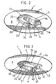
- Figure 2 is a perspective view of the upper side of a pressuriser device in accordance with the present invention;
- Figure 3 is a perspective view of the underside of the pressuriser device of Figure 2;
- Figures 4a, 4b and 4c are a top plan, side view and underneath plan of the cement pressuriser of Figure 2;
- Figures 5a, 5b and 5c are a top plan, cross-section and underneath plan of the cement pressuriser of Figure 2.
-
- Referring to the drawings, there is provided a
pressuriser device 1 with anupper side 2 and anunderneath side 4. Thepressuriser device 1 has a collar in the form of abody portion 6 and a radially surroundingflexible flange 8. - The present invention will be described in relation to a prosthetic hip stem for insertion in a femoral canal by means of a cement mantle. However, the
pressuriser device 1 is suitable for use with any form of cemented prosthetic component. - Figure 1 shows the position of a
pressuriser device 1 at the opening of afemoral cavity 14. The surroundingfemur 12 has been broached to increase the size of thecavity 14 within it. Thecavity 14 is filled with cement before insertion of afemoral stem 10. Thepressuriser device 1 sits on thefemur lip 18 at the entrance to thecavity 14. Thehip stem 10 is inserted through acentral opening 50 in thebody 6 of thepressuriser device 1. - The
pressuriser device 1 has anupper portion 20 of abody 6, theupper portion 20 including a generally U-shapedmember 21. The U-shapedmember 21 has aflat top surface 22 with supportingwalls 24. Thewalls 24 are generally vertical except at theopen ends 54 of the U-shapedmember 21 which are angled away from thetop surface 22 towards their base. Theupper portion 20 also has asealing lip 28 generally surrounding the U-shapedmember 21 and thelip 28 has a greater width at the curved portion of the U-shapedmember 21 than at theopen ends 54. - The
walls 24 and theflat top surface 22 of the U-shapedmember 21 are joined by anbevelled surface 26. - The
inner walls 44 of theupper portion 20 of thebody 6 have a profile which is curved to correspond to the external shape of thehip stem 10. Theinner walls 44 define thecentral opening 50 in thebody 6. - The
flange 8 extends from the sealinglip 28 radially to form a flexible extension around thebody 6. - The
body 6 has anunderneath portion 30 with a U-shapedmember 31 of thinner dimensions than the U-shapedmember 21 of theupper protion 20. - The U-shaped
member 31 of theunderneath portion 30 is surrounded by anouter lip 38 with acurved lip 36 joining theouter lip 38 to the base of the U-shapedmember 31. - The U-shaped
member 31 of theunderneath portion 30 has aflat top surface 32 with supportingwalls 34. Thewalls 34 are generally vertical. Thecurved end 46 of the U-shapedmember 31 has an angledtop surface 48 angled from theflat top surface 32 towards the surroundingouter lip 38. - The
legs 40 of the U-shapedmember 31 havefree ends 41 with cut-away portions 42 such that thefree ends 41 are abrupt and vertical and within the U-shape defined by theupper portion 20. - The external profile of the
underneath portion 30 corresponds to the shape of the broachedcavity 14 in the bone. The surroundingouter lip 38 forms a shoulder which rests on the opening 18 to thebone cavity 14. - The
flange 8 is attached or moulded into thebody 6 between theouter lip 38 of theunderneath portion 30 and theupper sealing lip 28 of theupper portion 20 of thebody 6. Theflange 8 is transparent to allow clarity of positioning of thepressuriser device 1. - The
flange 8 has a diameter of approximately 10 centimetres and is 0.5 to 1 millimetre thick. Thesealing lip 28 and theouter lip 38 are approximately 3 millimetres thick. - The
body 6 is formed of silicon rubber and, in this example, is provided in six sizes corresponding to different sizes of the femoral bone. - In use, the
pressuriser device 1 is positioned at theentrance 18 to a cement filledfemoral cavity 14 and ahip stem 10 is inserted through thecentral opening 50 in thebody 6 of thepressuriser device 1. Thehip stem 10 is inserted until it is correctly positioned within thecentral opening 50. The transparentflexible flange 8 maintains the pressure in the cement within thecavity 14. Theflange 8 is held down by the surgeon's hand around thefemur 12 as thehip stem 10 is inserted. - Modifications and improvements can be made to the foregoing without departing from the scope of the present invention.
Claims (14)
- A pressuriser device (1) in the form of a collar defining an opening for accommodating a prosthetic component (10) for insertion into a bone cavity (14), wherein the collar is surrounded by a radially extending flange (8) characterized in that said flange (8) is made of flexible material such that it can be held down around the bone in which the prosthetic component is inserted.
- A pressuriser device as claimed in claim 1, wherein the flexible flange (8) extends radially from the hollow collar such that the collar has an upper body portion (20) above the flexible flange and a lower body portion (30) below the flexible flange.
- A pressuriser device as claimed in claim 2, wherein the upper (20) and lower (30) body portions comprise generally U-shaped members (21, 31).
- A pressuriser device as claimed in claim 2 or claim 3, wherein the internal profile of the upper body portion (20) is adapted to correspond to the prosthetic component (10).
- A pressuriser device as claimed in any of claims 2 to 4, wherein the upper (20) and lower (30) body portions have sealing lips (28) in which the flexible flange is sealed.
- A pressuriser device as claimed in any of claims 2 to 5, wherein the external profile of the lower body portion (30) is shaped to correspond to a bone cavity (14) in which the prosthetic component is to be disposed.
- A pressuriser device as claimed in claim 3, wherein the upper body portion (20) has a shoulder adjacent the U-shaped member (21) which, in use, rests on the entrance to the bone cavity (14) in which the prosthetic component (10) is to be disposed.
- A pressuriser device as claimed in any of the preceding claims, wherein the flexible flange (8) is transparent to allow clarity of positioning.
- A pressuriser device as claimed in any of the preceding claims, wherein the prosthetic component (10) is a prosthetic hip stem and the bone cavity (14) is a femoral canal.
- A pressuriser device as claimed in any of claims 2 to 9, wherein the upper (20) and lower (30) body portions are formed of silicone rubber.
- A pressuriser device as claimed in any of claims 5 to 10, wherein the sealing lips (28) of the upper (20) and lower (30) body portions are approximately 3 millimetres thick.
- A pressuriser device as claimed in any of the preceding claims, wherein the flexible flange (8) is between 0.5 and 1 millimetre thick.
- A pressuriser device as claimed in any of the preceding claims, wherein the flexible flange (8) has a diameter of approximately 10 centimetres.
- A pressuriser device according to any of the preceding claims in combination with a prosthetic component (10).
Applications Claiming Priority (2)
| Application Number | Priority Date | Filing Date | Title |
|---|---|---|---|
| GBGB9816742.2A GB9816742D0 (en) | 1998-07-31 | 1998-07-31 | Pressuriser device |
| GB9816742 | 1998-07-31 |
Publications (3)
| Publication Number | Publication Date |
|---|---|
| EP0976369A2 EP0976369A2 (en) | 2000-02-02 |
| EP0976369A3 EP0976369A3 (en) | 2000-09-06 |
| EP0976369B1 true EP0976369B1 (en) | 2004-11-17 |
Family
ID=10836526
Family Applications (1)
| Application Number | Title | Priority Date | Filing Date |
|---|---|---|---|
| EP99306099A Expired - Lifetime EP0976369B1 (en) | 1998-07-31 | 1999-07-30 | Pressuriser device |
Country Status (5)
| Country | Link |
|---|---|
| US (1) | US6254641B1 (en) |
| EP (1) | EP0976369B1 (en) |
| JP (1) | JP2000060881A (en) |
| DE (1) | DE69921910T2 (en) |
| GB (1) | GB9816742D0 (en) |
Families Citing this family (3)
| Publication number | Priority date | Publication date | Assignee | Title |
|---|---|---|---|---|
| US6893445B1 (en) * | 1999-08-27 | 2005-05-17 | Ian Revie | Pressurizer device |
| US6938936B2 (en) * | 2001-09-12 | 2005-09-06 | General Electric Company | Energy absorber with crash cans |
| US20070016216A1 (en) * | 2005-05-02 | 2007-01-18 | Tague Christopher M | Delivery System Having A Nozzle With An Adjustable Spacer And Method Of Use Thereof For Improving Line-Of-Sight During A Medical Procedure And Pressurizer For Improving Line-Of-Sight During A Medical Procedure |
Family Cites Families (13)
| Publication number | Priority date | Publication date | Assignee | Title |
|---|---|---|---|---|
| US4012796A (en) * | 1975-09-24 | 1977-03-22 | Howmedica, Inc. | Interpositioning collar for prosthetic bone insert |
| DE2555717C3 (en) * | 1975-12-11 | 1981-11-19 | Joachim Prof. Dr.Med. 6200 Wiesbaden Eichler | Trochanteric plate for hip joint prostheses |
| CH622943A5 (en) * | 1977-11-30 | 1981-05-15 | Sulzer Ag | Trochanter plate |
| US4274163A (en) * | 1979-07-16 | 1981-06-23 | The Regents Of The University Of California | Prosthetic fixation technique |
| US4595006A (en) * | 1982-08-16 | 1986-06-17 | Burke Dennis W | Apparatus for cemented implantation of prostheses |
| GB8520360D0 (en) * | 1985-08-14 | 1985-09-18 | Thackray C F Ltd | Joint prosthesis |
| US4815454A (en) * | 1987-11-16 | 1989-03-28 | Dozier Jr John K | Apparatus and method for injecting bone cement |
| US4896662A (en) * | 1987-11-30 | 1990-01-30 | Pfizer Hospital Products Group, Inc. | Sealing device for introducing cement into a bone canal |
| DE3823287A1 (en) * | 1988-07-08 | 1990-01-11 | Draenert Klaus | MARKET CAVE SEALING DEVICE |
| DE3912465C1 (en) * | 1989-04-15 | 1990-11-08 | Orthoplant Endoprothetik Gmbh, 2800 Bremen, De | |
| DE19518391A1 (en) * | 1995-05-19 | 1996-11-21 | Schmidt Joachim Dr Med Priv Do | Femur seal for proximal centering and cementing in hip replacement |
| GB9510917D0 (en) * | 1995-05-30 | 1995-07-26 | Depuy Int Ltd | Bone cavity sealing assembly |
| US5741265A (en) * | 1996-02-21 | 1998-04-21 | Chan; Kwan-Ho | Bone canal pressurizer |
-
1998
- 1998-07-31 GB GBGB9816742.2A patent/GB9816742D0/en not_active Ceased
-
1999
- 1999-07-28 US US09/362,978 patent/US6254641B1/en not_active Expired - Fee Related
- 1999-07-30 EP EP99306099A patent/EP0976369B1/en not_active Expired - Lifetime
- 1999-07-30 JP JP11217870A patent/JP2000060881A/en active Pending
- 1999-07-30 DE DE69921910T patent/DE69921910T2/en not_active Expired - Fee Related
Also Published As
| Publication number | Publication date |
|---|---|
| GB9816742D0 (en) | 1998-09-30 |
| US6254641B1 (en) | 2001-07-03 |
| EP0976369A3 (en) | 2000-09-06 |
| EP0976369A2 (en) | 2000-02-02 |
| DE69921910D1 (en) | 2004-12-23 |
| JP2000060881A (en) | 2000-02-29 |
| DE69921910T2 (en) | 2005-12-01 |
Similar Documents
| Publication | Publication Date | Title |
|---|---|---|
| EP0149527B1 (en) | Fixation of implants in bone | |
| US5171289A (en) | Femoral prosthesis with cement retaining seal | |
| CA1145504A (en) | Bone plug | |
| US7429346B2 (en) | Method of forming a temporary prosthetic joint using a disposable mold | |
| AU628424B2 (en) | Femoral stem distal centralizer | |
| AU732184B2 (en) | Method and apparatus for performing hip prosthesis surgery | |
| US6187012B1 (en) | Prosthetic element removal apparatus and methods | |
| US4888024A (en) | Prosthetic device and method of fixation within the medullary cavity of bones | |
| CN102512268B (en) | Acetabulum comprising sterile interface | |
| EP1125561B1 (en) | Metal jacket for a cementless artificial joint stem and artificial joint having the metal jacket | |
| KR101651857B1 (en) | Prosthesis | |
| GB2043452A (en) | Protecting implantable prostheses | |
| EP0865776A3 (en) | Centering device for femoral implant | |
| EP1384456A3 (en) | Apparatus for acetabular reconstruction | |
| EP1269937A3 (en) | Prosthesis with resorbable collar | |
| AU2004212512A1 (en) | Prosthetic acetabular cup and prosthetic femoral joint incorporating such a cup | |
| ATE71822T1 (en) | SEALING FOR PLACEMENT OF BONE CEMENT INTO A BONE. | |
| US7211113B2 (en) | Hip prosthesis | |
| EP0565680B1 (en) | Hip prosthesis stem with a medullary cavity drainage system | |
| GB2331463A (en) | Unitary prosthetic foot and shin | |
| WO1991017723A1 (en) | Dummy device for moulding bone cavity form | |
| US6254641B1 (en) | Cement pressurizer with flange | |
| GB2042897A (en) | Prosthesis Sheath for Femoral Prosthesis | |
| JP4248629B2 (en) | Prosthesis assembly | |
| JP2865757B2 (en) | Medullary cavity sealing device |
Legal Events
| Date | Code | Title | Description |
|---|---|---|---|
| PUAI | Public reference made under article 153(3) epc to a published international application that has entered the european phase |
Free format text: ORIGINAL CODE: 0009012 |
|
| AK | Designated contracting states |
Kind code of ref document: A2 Designated state(s): DE FR GB IE IT |
|
| AX | Request for extension of the european patent |
Free format text: AL;LT;LV;MK;RO;SI |
|
| PUAL | Search report despatched |
Free format text: ORIGINAL CODE: 0009013 |
|
| AK | Designated contracting states |
Kind code of ref document: A3 Designated state(s): AT BE CH CY DE DK ES FI FR GB GR IE IT LI LU MC NL PT SE |
|
| AX | Request for extension of the european patent |
Free format text: AL;LT;LV;MK;RO;SI |
|
| 17P | Request for examination filed |
Effective date: 20010209 |
|
| AKX | Designation fees paid |
Free format text: DE FR GB IE IT |
|
| 17Q | First examination report despatched |
Effective date: 20030211 |
|
| GRAP | Despatch of communication of intention to grant a patent |
Free format text: ORIGINAL CODE: EPIDOSNIGR1 |
|
| GRAS | Grant fee paid |
Free format text: ORIGINAL CODE: EPIDOSNIGR3 |
|
| GRAA | (expected) grant |
Free format text: ORIGINAL CODE: 0009210 |
|
| AK | Designated contracting states |
Kind code of ref document: B1 Designated state(s): DE FR GB IE IT |
|
| REG | Reference to a national code |
Ref country code: GB Ref legal event code: FG4D |
|
| REG | Reference to a national code |
Ref country code: IE Ref legal event code: FG4D |
|
| REF | Corresponds to: |
Ref document number: 69921910 Country of ref document: DE Date of ref document: 20041223 Kind code of ref document: P |
|
| ET | Fr: translation filed | ||
| PLBE | No opposition filed within time limit |
Free format text: ORIGINAL CODE: 0009261 |
|
| STAA | Information on the status of an ep patent application or granted ep patent |
Free format text: STATUS: NO OPPOSITION FILED WITHIN TIME LIMIT |
|
| 26N | No opposition filed |
Effective date: 20050818 |
|
| PGFP | Annual fee paid to national office [announced via postgrant information from national office to epo] |
Ref country code: DE Payment date: 20080814 Year of fee payment: 10 |
|
| PGFP | Annual fee paid to national office [announced via postgrant information from national office to epo] |
Ref country code: IT Payment date: 20080730 Year of fee payment: 10 Ref country code: IE Payment date: 20080714 Year of fee payment: 10 Ref country code: FR Payment date: 20080718 Year of fee payment: 10 |
|
| PGFP | Annual fee paid to national office [announced via postgrant information from national office to epo] |
Ref country code: GB Payment date: 20080806 Year of fee payment: 10 |
|
| GBPC | Gb: european patent ceased through non-payment of renewal fee |
Effective date: 20090730 |
|
| REG | Reference to a national code |
Ref country code: FR Ref legal event code: ST Effective date: 20100331 |
|
| REG | Reference to a national code |
Ref country code: IE Ref legal event code: MM4A |
|
| PG25 | Lapsed in a contracting state [announced via postgrant information from national office to epo] |
Ref country code: FR Free format text: LAPSE BECAUSE OF NON-PAYMENT OF DUE FEES Effective date: 20090731 |
|
| PG25 | Lapsed in a contracting state [announced via postgrant information from national office to epo] |
Ref country code: GB Free format text: LAPSE BECAUSE OF NON-PAYMENT OF DUE FEES Effective date: 20090730 |
|
| PG25 | Lapsed in a contracting state [announced via postgrant information from national office to epo] |
Ref country code: DE Free format text: LAPSE BECAUSE OF NON-PAYMENT OF DUE FEES Effective date: 20100202 |
|
| PG25 | Lapsed in a contracting state [announced via postgrant information from national office to epo] |
Ref country code: IE Free format text: LAPSE BECAUSE OF NON-PAYMENT OF DUE FEES Effective date: 20090730 |
|
| PG25 | Lapsed in a contracting state [announced via postgrant information from national office to epo] |
Ref country code: IT Free format text: LAPSE BECAUSE OF NON-PAYMENT OF DUE FEES Effective date: 20090730 |