EP0975502B1 - Part mass separated from carbody - Google Patents
Part mass separated from carbody Download PDFInfo
- Publication number
- EP0975502B1 EP0975502B1 EP98917874A EP98917874A EP0975502B1 EP 0975502 B1 EP0975502 B1 EP 0975502B1 EP 98917874 A EP98917874 A EP 98917874A EP 98917874 A EP98917874 A EP 98917874A EP 0975502 B1 EP0975502 B1 EP 0975502B1
- Authority
- EP
- European Patent Office
- Prior art keywords
- mass
- carbody
- part mass
- car body
- frequency
- Prior art date
- Legal status (The legal status is an assumption and is not a legal conclusion. Google has not performed a legal analysis and makes no representation as to the accuracy of the status listed.)
- Expired - Lifetime
Links
- 238000000926 separation method Methods 0.000 claims abstract description 11
- 238000000034 method Methods 0.000 claims description 11
- 238000013016 damping Methods 0.000 claims description 6
- 230000010355 oscillation Effects 0.000 description 17
- 239000000725 suspension Substances 0.000 description 8
- 230000001133 acceleration Effects 0.000 description 4
- 238000005452 bending Methods 0.000 description 3
- 239000002184 metal Substances 0.000 description 2
- 229920001967 Metal rubber Polymers 0.000 description 1
- 240000005561 Musa balbisiana Species 0.000 description 1
- 235000018290 Musa x paradisiaca Nutrition 0.000 description 1
- 229910000831 Steel Inorganic materials 0.000 description 1
- 239000006096 absorbing agent Substances 0.000 description 1
- 238000010521 absorption reaction Methods 0.000 description 1
- 238000013459 approach Methods 0.000 description 1
- 230000005540 biological transmission Effects 0.000 description 1
- 238000001914 filtration Methods 0.000 description 1
- 230000003993 interaction Effects 0.000 description 1
- 230000003137 locomotive effect Effects 0.000 description 1
- 230000035945 sensitivity Effects 0.000 description 1
- 239000010959 steel Substances 0.000 description 1
Images

Classifications
-
- F—MECHANICAL ENGINEERING; LIGHTING; HEATING; WEAPONS; BLASTING
- F16—ENGINEERING ELEMENTS AND UNITS; GENERAL MEASURES FOR PRODUCING AND MAINTAINING EFFECTIVE FUNCTIONING OF MACHINES OR INSTALLATIONS; THERMAL INSULATION IN GENERAL
- F16F—SPRINGS; SHOCK-ABSORBERS; MEANS FOR DAMPING VIBRATION
- F16F7/00—Vibration-dampers; Shock-absorbers
- F16F7/10—Vibration-dampers; Shock-absorbers using inertia effect
- F16F7/1028—Vibration-dampers; Shock-absorbers using inertia effect the inertia-producing means being a constituent part of the system which is to be damped
-
- B—PERFORMING OPERATIONS; TRANSPORTING
- B61—RAILWAYS
- B61C—LOCOMOTIVES; MOTOR RAILCARS
- B61C3/00—Electric locomotives or railcars
-
- B—PERFORMING OPERATIONS; TRANSPORTING
- B61—RAILWAYS
- B61D—BODY DETAILS OR KINDS OF RAILWAY VEHICLES
- B61D17/00—Construction details of vehicle bodies
-
- B—PERFORMING OPERATIONS; TRANSPORTING
- B61—RAILWAYS
- B61D—BODY DETAILS OR KINDS OF RAILWAY VEHICLES
- B61D49/00—Other details
-
- F—MECHANICAL ENGINEERING; LIGHTING; HEATING; WEAPONS; BLASTING
- F16—ENGINEERING ELEMENTS AND UNITS; GENERAL MEASURES FOR PRODUCING AND MAINTAINING EFFECTIVE FUNCTIONING OF MACHINES OR INSTALLATIONS; THERMAL INSULATION IN GENERAL
- F16F—SPRINGS; SHOCK-ABSORBERS; MEANS FOR DAMPING VIBRATION
- F16F3/00—Spring units consisting of several springs, e.g. for obtaining a desired spring characteristic
- F16F3/08—Spring units consisting of several springs, e.g. for obtaining a desired spring characteristic with springs made of a material having high internal friction, e.g. rubber
- F16F3/10—Spring units consisting of several springs, e.g. for obtaining a desired spring characteristic with springs made of a material having high internal friction, e.g. rubber combined with springs made of steel or other material having low internal friction
-
- F—MECHANICAL ENGINEERING; LIGHTING; HEATING; WEAPONS; BLASTING
- F16—ENGINEERING ELEMENTS AND UNITS; GENERAL MEASURES FOR PRODUCING AND MAINTAINING EFFECTIVE FUNCTIONING OF MACHINES OR INSTALLATIONS; THERMAL INSULATION IN GENERAL
- F16F—SPRINGS; SHOCK-ABSORBERS; MEANS FOR DAMPING VIBRATION
- F16F7/00—Vibration-dampers; Shock-absorbers
- F16F7/10—Vibration-dampers; Shock-absorbers using inertia effect
- F16F7/104—Vibration-dampers; Shock-absorbers using inertia effect the inertia member being resiliently mounted
- F16F7/108—Vibration-dampers; Shock-absorbers using inertia effect the inertia member being resiliently mounted on plastics springs
-
- B—PERFORMING OPERATIONS; TRANSPORTING
- B60—VEHICLES IN GENERAL
- B60G—VEHICLE SUSPENSION ARRANGEMENTS
- B60G2202/00—Indexing codes relating to the type of spring, damper or actuator
- B60G2202/10—Type of spring
- B60G2202/12—Wound spring
-
- B—PERFORMING OPERATIONS; TRANSPORTING
- B60—VEHICLES IN GENERAL
- B60G—VEHICLE SUSPENSION ARRANGEMENTS
- B60G2202/00—Indexing codes relating to the type of spring, damper or actuator
- B60G2202/10—Type of spring
- B60G2202/14—Plastic spring, e.g. rubber
-
- B—PERFORMING OPERATIONS; TRANSPORTING
- B60—VEHICLES IN GENERAL
- B60G—VEHICLE SUSPENSION ARRANGEMENTS
- B60G2204/00—Indexing codes related to suspensions per se or to auxiliary parts
- B60G2204/10—Mounting of suspension elements
- B60G2204/16—Mounting of vehicle body on chassis
Definitions
- the present invention relates to a method and a device which prevent the occurrence of the drawbacks described at the vehicle speeds occurring.
- Structural stiffnesses in the carbody and the bogie together with a primary suspension at the wheel axles of the bogie are important parameters which influence the running properties of a train vehicle.
- Another important field to consider is the lateral dynamics of the vehicle, such as the interaction between the lateral movements of the bogies and the carbody. In this connection, the hunting of the bogies along the track, the running stability of the bogies and the cooperation between the hunting of the bogies and the oscillations of the carbody in the lateral direction exert an influence.
- the stiff-body frequencies for bogies are normally lower than the natural frequency of the carbody. Typical values for the stiff-body frequencies of the bogie are 5 to 8 Hz. Problems may arise when the natural frequency of the carbody approaches the stiff-body frequency of a bogie. Normally, the natural frequency of the carbody is kept higher than the stiff-body frequency of the bogie in that the carbody in accordance with prior art is designed with a high bending rigidity, that the carbody is short and further that its load is low. It has previously been possible to design vehicles in this way, when trains have been provided with passenger cars which have been pulled by locomotives. The cars may then be made ligher than in those cases where the cars in a train set consist of motor cars which comprise propulsion equipment. It has, of course, been possible to use long cars where the speed of a train has been lower than what is required in the case of high-speed trains.
- FIG. 1 shows the maximum deflection A for the oscillation of the carbody at one of the end positions of the oscillation as a function of its longitudinal position x. It is clear that the deflection is approximately zero at the respective bogie, whereas the ends of the carbody have large deflections in the same direction and the carbody centre a large deflection in the opposite direction. From this it is clear that the comfort for passengers is worst at the carbody centre and the car-body ends during oscillations with the natural frequency.
- the natural frequency of the carbody of the vehicle is increased by a part mass being separated dynamically from the carbody.
- the natural frequency of the carbody increases since the separated mass does not load the carbody dynamically.
- the separation of a part mass is achieved by the part mass being suspended resiliently from the carbody.
- the stiff-body frequency of the part mass is tuned in relation to the natural frequency of the main mass of the carbody, such that two natural frequencies are imparted to the cooperating system comprising the main mass of the carbody and its separated part mass, whereby the part mass oscillates most at a lower and the carbody with its main mass oscillates most at a higher frequency.
- the weight of the separated part mass is of importance. Up to a certain limit, the gain in comfort increases with the weight of the separated part mass.
- the weight of the part mass should amount to at least 10% of the remaining mass of the carbody in order for a noticeable improvement of the natural oscillation problems to be attained.
- the separated part mass according to the invention consists of a transformer package or of a separated underframe. There is no point in adding an extra mass as separated mass.
- a part mass of the carbody Since a part mass of the carbody is resiliently suspended, the natural frequency of the carbody will increase due to the fact that the part mass no longer needs to be included in the carbody weight. As a result of this, an increase of the natural frequency of the carbody of about 1 Hz is obtained. Further, if the natural frequency of the part mass is tuned in relation to the stiff-body frequency of the carbody, an additional increase of the natural frequency of the carbody of 1 Hz is obtained.
- a resilient suspension of a part mass of the carbody implies that the carbody may be given a natural frequency which is 2 Hz higher than without separation of the part mass.
- the natural frequency of the carbody in the lateral direction may thus be given values which exceed 10 Hz also for motor cars with lengths of about 26 m.
- a vehicle may be run at a higher speed than what would be the case with a vehicle designed in accordance with prior art, without lateral self-oscillations of the carbody creating problems with the comfort.
- Figure 1 illustrates the appearance of the self-oscillation in the form of the lateral deviation of the carbody from its position of equilibrium along its length x at a certain moment.
- B1 and B2 illustrate bogie positions of the car-body. At the bogies, the deflection of the oscillation is almost non-existent. The greatest deflection takes place at the centre of the carbody and, to a certain extent, also at the ends of the car.
- accelerations of the carbody are obtained according to Figure 2, where the acceleration, a, of the carbody is plotted as a function of the frequency f.
- This example shows a first oscillation peak at the frequency f 1 corresponding to the stiff-body frequency of the oppositely oscillating part mass and a second oscillation peak at the frequency f 2 for the main mass of the carbody.
- the natural frequency of the oppositely oscillating mass is 6 Hz
- the rest of the carbody has the natural frequency 10 Hz. Without the described separation of a part mass, it may be read from the dash-lined curve that the natural frequency of the carbody is about 8 Hz.
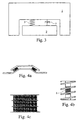
- FIG. 3 An execution of a dynamic separation according to the invention is clear from Figure 3.
- a carbody has been divided into the main mass 1 of the carbody and a separated part mass 2.
- the part mass is dynamically separated from the main mass 1 by means of a spring 3.
- a damper 5 is also arranged between the main mass and the part mass.
- Both the spring 3 and the damper 5 are utilized in the number which is necessary for achieving the necessary resilience and damping and for absorption of forces, respectively.
- the spring and the damper are suitably designed also in such a way that the natural frequency for the main mass of the carbody becomes as high as possible. Calculations have shown that the best comfort inside the carbody is obtained if the oppositely oscillating part mass is given a solid-body frequency in the order of magnitude of 2 Hz lower than the natural frequency of the carbody.
- the most suitable part mass 2 in a carbody, in which the natural frequency is to be raised according to the inventive aspect, is a transformer present in the car.
- a transformer has a sufficient weight to achieve the necessary increase of the natural frequency for the car-body.
- the transformer is suspended by means of suitable springs 3.
- Figure 4a shows a rubber spring. This variant with rubber elements between roof-shaped metal linings is especially suitable when it is desired to obtain different spring constants in different directions, for example laterally and longitudinally.
- Figure 4b illustrates a helical spring of a special type in which the spring is combined with a knitted steel wire 6 to give the spring a desired damping.
- a disadvantage of this type of spring may be its space requirement.
- FIG. 4c A further variant of spring is shown in Figure 4c, in which a metal-rubber spring is shown.
- a metal-rubber spring is shown.
- Such a spring is built up of layered metal plates with rubber liners between every other layer.
- the suspension of, for example, a transformer for achieving the desired separated mass may be carried out with the desired number of springs.
- the separation is carried out by means of one spring in each corner, where in each corner one of, for example, some of the spring types according to Figures 4a-4c is applied.
- the suspension may be tuned such that the natural frequency for the main mass of the carbody may be optimally increased.
- the springs 3 are provided with internal damping means, shown in the figures as dampers 5. These dampers carry away energy such that an oscillation arisen may be damped in a known manner. It is, of course, possible to arrange separate dampers between the part mass and the carbody, if this should be considered justified.
- the location of the oppositely oscillating mass is preferably near the centre of the carbody in the longitudinal direction, or at some of its ends, since the movements of the carbody are greatest at these positions.
Landscapes
- Engineering & Computer Science (AREA)
- General Engineering & Computer Science (AREA)
- Mechanical Engineering (AREA)
- Transportation (AREA)
- Vibration Prevention Devices (AREA)
Abstract
Description
The result of all this is that the natural frequencies of the carbodies decrease. A long car imparts a lower natural frequency to the carbody. The requirements for the location, size and entrances of the doors reduce the possibilities of giving the carbodies sufficient bending rigidity, while at the same time measures increasing the bending rigidity increase the weight of the carbody. The requirements for the vehicle being designed as a motor car increase the load of the carbody, in which case also this leads to a reduced natural frequency of the carbody.
Claims (15)
- A method in a railway vehicle which comprises a car body and at least two running gears for increasing the difference in frequency between the natural frequency of the car body and the stiff-body frequencies of a running gear, wherein a part mass (2) is separated dynamically from a main mass (1) of the car body for reducing vibrations of the car body, the part mass (2) being resiliently suspended to the car body by means of a spring (3), damping (5) being arranged between the part mass (2) and the main mass (1).
- A method according to claim 1, Wherein the stiff-body frequency of the part mass (2) is tuned in relation to the natural frequency of the main mass (1) of the car body, such that two natural frequencies are imparted to the cooperating system comprising the main mass (1) of the car body and its separated part mass (2), whereby the part mass (2) oscillates most at a lower and the car body with its main mass (1) oscillates most at a higher frequency.
- A method according to any of the preceding claims, wherein the part mass (2) constitutes at least 10% of the weight of the car body.
- A method according to any of the preceding claims, wherein the solid-body frequency of the part mass (2) is in the order of magnitude of 2 Hz lower than the natural frequency of the car body.
- A method according to any of the preceding claims, wherein the part mass (2) is a transformer.
- A method according to any of the claims 1 to 4, wherein the part mass (2) is a car under-frame.
- A method according to any of the preceding claims, wherein the dynamic separation is carried out in at least one of the main directions of the vehicle laterally, longitudinally or vertically.
- A method according to any of the preceding claims, wherein the part mass (2) is suspended resiliently near the centre of the vehicle or at one of the ends of the vehicle.
- A method according to any of the preceding claims, wherein the natural frequency imparted to the main mass (1) is higher than the stiff-body frequencies of the running gears.
- A railway vehicle which comprises a car body supported by at least two running gear, wherein a part mass (2) that constitutes at least 10% of the weight of the car body is separated dynamically from a main mass (1) of the car body whereby the natural frequency of the main mass (1) is higher than the stiff-body frequencies of the running gear, the part mass (2) being resiliently suspended to the car body by means of a spring (3), damping (5) being arranged between the part mass (2) and the main mass (1).
- A railway vehicle according to claim 10, wherein the stiff-body frequency of the part mass (2) is such that two natural frequencies are imparted to the cooperating system comprising the main mass (1) of the car body and its separated part mass (2), whereby the part mass (2) oscillates most at a lower and the car body with its main mass (1) oscillates most at a higher frequency.
- A railway vehicle according to claim 10 or 11, wherein the solid-body frequency of the part mass (2) is in the order of magnitude of 2 Hz lower than the natural frequency of the car body.
- A railway vehicle according to any one of claims 10 to 12, wherein the part mass (2) consists of a transformer.
- A railway vehicle according to any one of claims 10 to 13, wherein the part mass (2) consists of a car under-frame.
- A railway vehicle according to any one of claims 10 to 14, wherein the separated part mass (2) is located at the longitudinal centre of the vehicle or at one of the ends of the vehicle.
Applications Claiming Priority (3)
| Application Number | Priority Date | Filing Date | Title |
|---|---|---|---|
| SE9701378A SE509118C2 (en) | 1997-04-15 | 1997-04-15 | Part mass separated from wagon basket |
| SE9701378 | 1997-04-15 | ||
| PCT/SE1998/000658 WO1998046467A1 (en) | 1997-04-15 | 1998-04-09 | Part mass separated from carbody |
Publications (2)
| Publication Number | Publication Date |
|---|---|
| EP0975502A1 EP0975502A1 (en) | 2000-02-02 |
| EP0975502B1 true EP0975502B1 (en) | 2005-01-12 |
Family
ID=20406560
Family Applications (1)
| Application Number | Title | Priority Date | Filing Date |
|---|---|---|---|
| EP98917874A Expired - Lifetime EP0975502B1 (en) | 1997-04-15 | 1998-04-09 | Part mass separated from carbody |
Country Status (5)
| Country | Link |
|---|---|
| EP (1) | EP0975502B1 (en) |
| AT (1) | ATE286819T1 (en) |
| AU (1) | AU737691B2 (en) |
| SE (1) | SE509118C2 (en) |
| WO (1) | WO1998046467A1 (en) |
Families Citing this family (12)
| Publication number | Priority date | Publication date | Assignee | Title |
|---|---|---|---|---|
| US6298791B1 (en) | 1999-11-11 | 2001-10-09 | Raytheon Company | Lateral suspension assembly for a guided vehicle system |
| US6308636B1 (en) | 1999-11-11 | 2001-10-30 | Raytheon Company | In-vehicle switch mechanism |
| US6637561B1 (en) * | 1999-11-11 | 2003-10-28 | Raytheon Company | Vehicle suspension system |
| US6418856B2 (en) | 1999-11-11 | 2002-07-16 | Raytheon Company | Passive steering assembly for a guided vehicle |
| ATE506238T1 (en) * | 2008-09-17 | 2011-05-15 | Stadler Winterthur Ag | RAIL VEHICLE |
| EP2763880B2 (en) † | 2011-10-05 | 2022-07-06 | Bombardier Transportation GmbH | Rail vehicle having a sound-insulated and vibration-insulated room-within-a-room cab |
| JP6384867B2 (en) * | 2014-11-05 | 2018-09-05 | 三菱重工エンジニアリング株式会社 | Railway compressor equipment, railway vehicles |
| CN104590302B (en) * | 2014-12-02 | 2017-12-05 | 南车株洲电力机车有限公司 | A kind of rail vehicle and counter weight device |
| US9694829B2 (en) | 2014-12-18 | 2017-07-04 | Electro-Motive Diesel, Inc. | Device for controlling stiffness and damping of locomotive carbodies |
| DE102020200473A1 (en) * | 2020-01-16 | 2021-07-22 | Siemens Mobility GmbH | Fastening device for the elastic suspension of a vehicle component |
| CN113581150B (en) * | 2021-07-02 | 2022-06-07 | 交控科技股份有限公司 | Brake system for rail vehicles adapted to a detachable car body |
| JP2024021524A (en) * | 2022-08-03 | 2024-02-16 | 株式会社日立製作所 | railway vehicle |
Family Cites Families (3)
| Publication number | Priority date | Publication date | Assignee | Title |
|---|---|---|---|---|
| SU1142339A1 (en) * | 1983-10-13 | 1985-02-28 | Всесоюзный Ордена Трудового Красного Знамени Научно-Исследовательский Институт Железнодорожного Транспорта | Device for reducing vibrations of vehicle body |
| SU1463589A1 (en) * | 1987-05-06 | 1989-03-07 | Волгоградский Политехнический Институт | Arrangement for decreasing vibrations of vehicle body |
| SU1523444A1 (en) * | 1987-09-28 | 1989-11-23 | Всесоюзный Научно-Исследовательский Институт Железнодорожного Транспорта | Vibration damper for railway vehicle body |
-
1997
- 1997-04-15 SE SE9701378A patent/SE509118C2/en not_active IP Right Cessation
-
1998
- 1998-04-09 AU AU70923/98A patent/AU737691B2/en not_active Ceased
- 1998-04-09 WO PCT/SE1998/000658 patent/WO1998046467A1/en not_active Ceased
- 1998-04-09 EP EP98917874A patent/EP0975502B1/en not_active Expired - Lifetime
- 1998-04-09 AT AT98917874T patent/ATE286819T1/en active
Also Published As
| Publication number | Publication date |
|---|---|
| SE9701378L (en) | 1998-10-16 |
| AU737691B2 (en) | 2001-08-30 |
| SE9701378D0 (en) | 1997-04-15 |
| AU7092398A (en) | 1998-11-11 |
| SE509118C2 (en) | 1998-12-07 |
| ATE286819T1 (en) | 2005-01-15 |
| WO1998046467A1 (en) | 1998-10-22 |
| EP0975502A1 (en) | 2000-02-02 |
Similar Documents
| Publication | Publication Date | Title |
|---|---|---|
| AU737691B2 (en) | Part mass separated from carbody | |
| US4765251A (en) | Railway car truck with multiple effective spring rates | |
| CA1148029A (en) | Bolsterless bogie with air-spring suspension for rail vehicles | |
| Hui et al. | Vertical vibration analysis of the flexible carbody of high speed train | |
| Orvnäs | Methods for reducing vertical carbody vibrations of a rail vehicle: a literature survey | |
| US8939086B2 (en) | Running gear for a rail vehicle with a transversally decoupling motor suspension | |
| Yau et al. | Resonance reduction for linked train cars moving on multiple simply supported bridges | |
| Stribersky et al. | The development of an integrated suspension control technology for passenger trains | |
| Celniker et al. | Rail vehicle active suspensions for lateral ride and stability improvement | |
| RU2291801C2 (en) | Railway vehicle two-axle bogie | |
| US2384925A (en) | Vehicle suspension | |
| RU226420U1 (en) | ELASTIC IN THE TRANSVERSE DIRECTION MOUNTING OF THE MOTOR-GEAR UNIT OF CLASS III TRACTION DRIVE ACCORDING TO A SYMMETRICAL SCHEME OF SUPPORT POINTS | |
| Foo et al. | Active suspension control strategies for flexible-bodied railway vehicles | |
| RU225826U1 (en) | SPRING SUSPENSION OF A FREIGHT CAR TROLLEY | |
| Lu et al. | On-track experiments on the ride comforts of an articulated railway vehicle | |
| HIDAI et al. | Analysis of vibration transmissibility of railway vehicles while transiting curves with lateral track irregularity | |
| JPH09301163A (en) | Bolsterless bogie for vehicle | |
| US2064464A (en) | Truck | |
| Petrović et al. | Approximation of ideal characteristic of railway vehicle suspension | |
| Guo et al. | Experimental investigation on vibration characteristics and frequency domain of heavy haul locomotives | |
| EP1187749B1 (en) | Rail vehicle | |
| JP2011201476A (en) | Railroad vehicle, and method of suppressing vibration of vehicle body of the same | |
| Leblebici et al. | The Track Roughness Effect on the Actively Controlled Railway Vehicle | |
| Bullock et al. | Optimizing railroad freight car truck suspension systems having Coulomb damping | |
| Lu et al. | Track-transmission system dynamic analysis |
Legal Events
| Date | Code | Title | Description |
|---|---|---|---|
| PUAI | Public reference made under article 153(3) epc to a published international application that has entered the european phase |
Free format text: ORIGINAL CODE: 0009012 |
|
| 17P | Request for examination filed |
Effective date: 19991112 |
|
| AK | Designated contracting states |
Kind code of ref document: A1 Designated state(s): AT CH FR GB IT LI PT SE |
|
| RAP1 | Party data changed (applicant data changed or rights of an application transferred) |
Owner name: DAIMLERCHRYSLER AG |
|
| 17Q | First examination report despatched |
Effective date: 20020617 |
|
| RAP1 | Party data changed (applicant data changed or rights of an application transferred) |
Owner name: BOMBARDIER TRANSPORTATION GMBH |
|
| GRAP | Despatch of communication of intention to grant a patent |
Free format text: ORIGINAL CODE: EPIDOSNIGR1 |
|
| GRAS | Grant fee paid |
Free format text: ORIGINAL CODE: EPIDOSNIGR3 |
|
| GRAA | (expected) grant |
Free format text: ORIGINAL CODE: 0009210 |
|
| AK | Designated contracting states |
Kind code of ref document: B1 Designated state(s): AT CH FR GB IT LI PT SE |
|
| REG | Reference to a national code |
Ref country code: GB Ref legal event code: FG4D |
|
| REG | Reference to a national code |
Ref country code: CH Ref legal event code: EP |
|
| PG25 | Lapsed in a contracting state [announced via postgrant information from national office to epo] |
Ref country code: SE Free format text: LAPSE BECAUSE OF FAILURE TO SUBMIT A TRANSLATION OF THE DESCRIPTION OR TO PAY THE FEE WITHIN THE PRESCRIBED TIME-LIMIT Effective date: 20050412 |
|
| REG | Reference to a national code |
Ref country code: CH Ref legal event code: NV Representative=s name: A. BRAUN, BRAUN, HERITIER, ESCHMANN AG PATENTANWAE |
|
| PLBE | No opposition filed within time limit |
Free format text: ORIGINAL CODE: 0009261 |
|
| STAA | Information on the status of an ep patent application or granted ep patent |
Free format text: STATUS: NO OPPOSITION FILED WITHIN TIME LIMIT |
|
| ET | Fr: translation filed | ||
| 26N | No opposition filed |
Effective date: 20051013 |
|
| PG25 | Lapsed in a contracting state [announced via postgrant information from national office to epo] |
Ref country code: PT Free format text: LAPSE BECAUSE OF NON-PAYMENT OF DUE FEES Effective date: 20050612 |
|
| REG | Reference to a national code |
Ref country code: CH Ref legal event code: PFA Owner name: BOMBARDIER TRANSPORTATION GMBH Free format text: BOMBARDIER TRANSPORTATION GMBH#SAATWINKLER DAMM 43#13627 BERLIN (DE) -TRANSFER TO- BOMBARDIER TRANSPORTATION GMBH#SAATWINKLER DAMM 43#13627 BERLIN (DE) |
|
| PGFP | Annual fee paid to national office [announced via postgrant information from national office to epo] |
Ref country code: GB Payment date: 20120419 Year of fee payment: 15 Ref country code: FR Payment date: 20120507 Year of fee payment: 15 |
|
| PGFP | Annual fee paid to national office [announced via postgrant information from national office to epo] |
Ref country code: IT Payment date: 20120426 Year of fee payment: 15 |
|
| PGFP | Annual fee paid to national office [announced via postgrant information from national office to epo] |
Ref country code: AT Payment date: 20120411 Year of fee payment: 15 |
|
| REG | Reference to a national code |
Ref country code: AT Ref legal event code: MM01 Ref document number: 286819 Country of ref document: AT Kind code of ref document: T Effective date: 20130430 |
|
| GBPC | Gb: european patent ceased through non-payment of renewal fee |
Effective date: 20130409 |
|
| PG25 | Lapsed in a contracting state [announced via postgrant information from national office to epo] |
Ref country code: GB Free format text: LAPSE BECAUSE OF NON-PAYMENT OF DUE FEES Effective date: 20130409 Ref country code: AT Free format text: LAPSE BECAUSE OF NON-PAYMENT OF DUE FEES Effective date: 20130430 |
|
| REG | Reference to a national code |
Ref country code: FR Ref legal event code: ST Effective date: 20131231 |
|
| PG25 | Lapsed in a contracting state [announced via postgrant information from national office to epo] |
Ref country code: IT Free format text: LAPSE BECAUSE OF NON-PAYMENT OF DUE FEES Effective date: 20130409 Ref country code: FR Free format text: LAPSE BECAUSE OF NON-PAYMENT OF DUE FEES Effective date: 20130430 |
|
| REG | Reference to a national code |
Ref country code: CH Ref legal event code: PCAR Free format text: NEW ADDRESS: HOLBEINSTRASSE 36-38, 4051 BASEL (CH) |
|
| PGFP | Annual fee paid to national office [announced via postgrant information from national office to epo] |
Ref country code: CH Payment date: 20150420 Year of fee payment: 18 |
|
| REG | Reference to a national code |
Ref country code: CH Ref legal event code: PL |
|
| PG25 | Lapsed in a contracting state [announced via postgrant information from national office to epo] |
Ref country code: CH Free format text: LAPSE BECAUSE OF NON-PAYMENT OF DUE FEES Effective date: 20160430 Ref country code: LI Free format text: LAPSE BECAUSE OF NON-PAYMENT OF DUE FEES Effective date: 20160430 |