EP0975129A2 - Device and method for adapting accessory apparatuses to an analog telecommunication terminal - Google Patents
Device and method for adapting accessory apparatuses to an analog telecommunication terminal Download PDFInfo
- Publication number
- EP0975129A2 EP0975129A2 EP99110117A EP99110117A EP0975129A2 EP 0975129 A2 EP0975129 A2 EP 0975129A2 EP 99110117 A EP99110117 A EP 99110117A EP 99110117 A EP99110117 A EP 99110117A EP 0975129 A2 EP0975129 A2 EP 0975129A2
- Authority
- EP
- European Patent Office
- Prior art keywords
- output unit
- network access
- voice input
- access line
- terminal
- Prior art date
- Legal status (The legal status is an assumption and is not a legal conclusion. Google has not performed a legal analysis and makes no representation as to the accuracy of the status listed.)
- Granted
Links
Images


Classifications
-
- H—ELECTRICITY
- H04—ELECTRIC COMMUNICATION TECHNIQUE
- H04M—TELEPHONIC COMMUNICATION
- H04M1/00—Substation equipment, e.g. for use by subscribers
- H04M1/60—Substation equipment, e.g. for use by subscribers including speech amplifiers
- H04M1/6033—Substation equipment, e.g. for use by subscribers including speech amplifiers for providing handsfree use or a loudspeaker mode in telephone sets
-
- H—ELECTRICITY
- H04—ELECTRIC COMMUNICATION TECHNIQUE
- H04M—TELEPHONIC COMMUNICATION
- H04M1/00—Substation equipment, e.g. for use by subscribers
- H04M1/02—Constructional features of telephone sets
- H04M1/21—Combinations with auxiliary equipment, e.g. with clocks or memoranda pads
- H04M1/215—Combinations with auxiliary equipment, e.g. with clocks or memoranda pads by non-intrusive coupling means, e.g. acoustic couplers
Definitions
- the invention relates to a method for adapting additional devices, such as answering machines, hands-free systems, dialing aids and the like, to an analog terminal for telecommunications, especially on a phone.
- the invention relates furthermore an apparatus for performing the method.
- Telecommunications terminal equipment in particular simple telephones, are often to be replaced by additional devices, e.g. Answering machine, speakerphone, Election aids, be upgraded.
- additional devices e.g. Answering machine, speakerphone, Election aids
- the terminal device to be expanded directly take by either existing modification additions of the terminals used or, if these are not available, the internal Wiring of the terminal is modified accordingly.
- the first Approach requires that the end device to be expanded for Modifications for an additional device is prepared. This is often not the case, especially with simple analog telephones.
- the second approach assumes that the user of the terminal either has sufficient technical knowledge to handle the internal Interconnection of the terminal in a suitable manner, or ready to change is to hire an appropriate specialist.
- the invention is therefore based on the object of a method for Adaptation of additional devices to analog terminal devices for the Telecommunications, especially in the speech path of the to be expanded Additional equipment interfering with terminal equipment, to be specified at which interferes with the analog terminal to be expanded become.
- the invention is also based on the object Specify device which for upgrading terminal equipment with Additional devices can be used universally.
- the task is solved by a method for the adaptation of Additional devices to an analog terminal for telecommunications according to claim 1.
- the task is still solved by a device for performing the method according to Claim 6.
- Advantageous further developments of the method and Devices are described in subclaims 2 to 5 and 7 to 9, respectively.
- the solution according to the invention is based on the fact that the insertion of a Additional device in the speech path of an analog terminal is done in such a way that the actuation functions for a connection setup or clearing are required, can be carried out in the usual way and the electrical conditions in view of the telephone network remain unchanged.
- the mechanical functions e.g. Entering dialing commands on a keyboard
- the speech functions the terminal separated by a parallel network connection of the to be expanded analog terminal and the additional device under Avoid influencing the standardized line termination resistance is made.
- the original speech path is decoupled from the Terminal device with high impedance on its network access line accessed, receiving the standardized line termination resistance remains.
- the tapped signal is preferably proportional to Speech signal coming from the telephone network to the terminal is transmitted. This via the network access line directly to the end device transmitted voice signal is in contrast to normal functioning of the terminal in the present invention no further Realization of the speech function exploited.
- the original speech path and voice input and output device the terminal device, in particular the telephone handset, rather remains unused.
- the telephone handset can be removed.
- the additional device To implement a new speech path in which the additional device is located can be inserted without any problems, this is now from the network access line high-impedance tapped speech signal or one proportional signal to the additional device and to one of the Terminal device electrically separated voice input and output unit guided.
- the tapped speech signal is preferably used before coupling in the additional device or the voice input and output unit amplified to bring it up to about the signal level that the above the network access line has transmitted signal.
- "coming" speech signals that is, those that are transmitted via the Telephone network to be transmitted to the terminal, to the additional device as well as to a speech output unit, such as a loudspeaker, headed.
- the user can do this in a known manner in an acoustic Hear the converted voice signal.
- the additional device record the voice signals or otherwise influence them take them e.g. Play loudly as a speakerphone.
- the "outgoing" signals that is to say those which are generally entered acoustically by the user and for transmission over the telephone network into an electronic one Signal-converted speech signals are in the invention on a Voice input unit entered, which is also from the upgraded Terminal is electrically isolated.
- the original speech path of the end device remains unused according to the invention also for the input of voice signals.
- the device to be upgraded can also be used at any time Additional devices work, i.e. the original speech path becomes not completely disabled or interrupted.
- an output signal which is usually also spoken language corresponds, e.g. an announcement.
- the output signal of the voice input unit and / or the additional device then becomes high-resistance while maintaining the line termination resistance coupled into the network access line of the terminal to be upgraded.
- a voltage-controlled current source is preferred used.
- the output signal from the voice input unit is used and / or additional device for controlling the current flow of the current source, the output of which is connected to the network access line.
- outgoing signals that are both directly from the User or the voice input unit as well as from the additional device generated are coupled into the network access line as a voice signal and transmitted over the telephone network.
- dialing and other tax functions will continue used the terminal.
- the selection and control signals are in known manner from the terminal by keyboard input or the like generated and directly via the network access line to the telephone network forwarded.
- dialing and control signals reach from the Switch were generated, the terminal directly over the Network access line. This ensures that the user Can continue to use the terminal in the usual way. They are not modifications the control of the terminal is necessary.
- the additional device and / or the voice input and output unit in independence functionally switched on or off by the activity of the terminal.
- the voltage level on the network access line measured and the additional device and / or the voice input and output unit activated or deactivated depending on this.
- the Measurement of the voltage level on the network access line is, for example made with a comparator on the network access line accesses and provides an output signal when the voltage level exceeds or falls below a predetermined sound threshold. This switching signal serves the additional device and / or the voice input and - Switch output unit on or off.
- the activity can be determined also to an economic shutdown of the total power supply be used.
- an analog terminal for telecommunications is connected with a device 18 for adapting additional devices shown.
- the additional device itself is according to Figure 2 in the device 18 integrated and not shown here.
- the terminal 4 has a handset rest 2, on which the Telephone receiver 1 as a voice input and output unit of the terminal 4 lies on.
- the hybrid circuit 3 is the electrical contact to the telephone network via the Network access line 6, with the components 6.1 and 6.2 shown here producible.
- Dialing unit e.g. a keyboard
- entered dialing commands and the am Voice signals entered as an electronic signal to the telephone handset Transfer the telephone network and to the communication partner.
- voice signals is therefore the telephone handset 1 of a standard terminal via a connection 20 on the terminal directly to the terminal and the components therein, in particular a converter circuit 9 and the network access line 6 connected.
- On the phone Input signals are thus directly on the network access line 6 given.
- the terminal is modified on this point:
- the telephone handset 1 is not connected to the connection via the connecting line 5 20 on the terminal, but with an interface 19 on the invention Device 18 connected.
- the Originally removed 4 existing handset on the terminal and to the Device 18 can be connected to the interface 19.
- a voice input and output unit which by is coupled in advance with the device 18 on the handset rest 2 of the to be upgraded terminal 4.
- voice input on a voice input unit 1 which is directly electronic are coupled to the device 18.
- the voice input unit is for example the mouthpiece of a listener together with the corresponding one Electronics or the microphone of a hands-free device.
- the Speech output unit is the earpiece of a listener or the Speakerphone of a speakerphone
- the Mains connection of the terminal 4 is not in the example shown here directly connected to the telephone network, but as a power cord 6.1 first with the device 18.
- Establishing the connection between Terminal 4 and device 18 take place via a first interface 8, which e.g. is an analog a / b interface.
- the network access of the terminal 4 to Telephone network is via the network access line 6.1 of the terminal and the Network access line 6.2 of the device 18 made by the first Interface 8 within the device 18 with the power cord 6.2 is coupled, see Figure 2.
- the entire network access line 6 is thus looped through device 18, according to the invention the network access line is accessed within the device.
- the device 18 is connected to the network access line 6.2 Telephone network connected.
- the device 18 is equipped with a voice input and output unit 1, if not already one Is part of the device 18.
- This voice input and output unit 1, here a telephone handset is placed on the handset rest 2 of the terminal hung up, the handset originally assigned to the terminal by the Handset rest is removed. A mechanical decoupling of the original existing handset is not necessary.
- the network access line 6.1 of the terminal 4 via the first interface 8 with the Device 18 connected.
- Block diagram of Figure 2 used.
- the lower part of Figure 2 shows the basic structure of the Device 18 for adapting additional devices, the Additional device 7 is integrated in the device 18.
- the components of a standard telephone 4 relating to the invention are the telephone handset 1 ', the hybrid circuit 3, the line terminating resistor 10 and the 2-wire / 4-wire conversion 9.
- the telephone handset 1 ' is over a Connection 20 and a corresponding connection line to the terminal 4 connected.
- the telephone receiver 1 ′ of the terminal 4 however not used; the original speech path of the terminal 4 remains unused.
- the handset is located instead of the standard telephone handset 1 ' 1 of the device 18 in the idle state on the handset rest 2, as in FIG. 1 shown.
- Terminal 4 and device 18 are on the power cord 6.1 of the Terminal 4 connected to each other.
- the power cord 6.1 which is connected directly to a mains socket in the standard case, first via a first interface 8 with one inside the Device 18 extending network access line section 6.3 connected, which is brought out as a network access line 6.2 of the device 18.
- the line section 6.2 forms the network access line of the device with which can be connected to a telephone network.
- the three management elements 6.1, 6.3 and 6.2 form the network access line of the Terminal 4, via which signaling signals, such as dialing and other Control characters, from the terminal via the device 18 to the telephone network and are reversely transferable.
- Terminal 4 and device 18 are thus coupled in two ways: Firstly, there is an electrical coupling by the network access line of the terminal looped through the device 18 , with speech signals being coupled out or in within the device 18 become. On the other hand, there is a coupling between the final and Additional device by the voice input and output unit 1 with the Device 18 via a connecting line 5 (5.1, 5.2) electrically and with the terminal 4 mechanically by resting on its handset support is coupled.
- the mechanical coupling through which the hybrid circuit 3 can be operated is in Figure 2 by a dashed line from the telephone handset 1 indicated for fork 3.
- connection establishment begins with simple terminals 4 so that the Telephone receiver 1 is lifted. This initially creates a mechanical Closing the fork contact 3 via the handset rest 2, which also electrical connection to an exchange or private branch exchange is brought about via the power cord 6. Via the power cord the phone also receives an electrical supply Energy required for the phone to function properly.
- the open circuit voltage drops on the power cord 6 to a significantly lower Value.
- the open circuit voltage is usually approx. 24 to 70 V.
- the Voltage about 8 to 12 V.
- a dialing unit e.g. the user of the terminal 4 gives a keyboard Dialing commands, which are converted into electrical signals that over the power cord 6 are transmitted.
- the speech paths begin Action.
- the power cord on the end device side terminated with a standardized line resistance 10 (alternating current) his.
- a standardized line resistance 10 alternating current
- the network line 6 (6.2, 6.3, 6.1) transmitted voice signal is transmitted by means of the converter 9 to the speaker of the telephone handset 1 ', which is connected to the microphone of the Telephone handset 1 'entered voice signal is converted by the converter 9 in the power cord is coupled.
- This standard speech path with the Telephone receiver 1 'as the interface to the user remains with the present Invention unused, but in principle functional.
- Voice signals that come from the telephone network, over the Power cord 6.2 to the device 18 and then through the Line elements 6.3 and 6.1 are transmitted to the terminal, tapped within the device 18.
- the voice input and output unit 1 entered acoustic signals converted into electrical voice signals, via line 5.2 to device 18 and additional device 7 transmitted and within the device in the power cord 6th coupled.
- the speech path of the terminal is over the Device 18 guided, with an additional device 7 in the speech path was integrated, see Fig. 3.
- the other functions of the analog Terminal 4 in particular control by keyboard input and the like, are by decoupling the speech path by means of Device 18 is not affected because these signaling signals are still on the power cord 6, consisting of the Elements 6.1, 6.3 and 6.2.
- the line terminating resistor 10 is not falsified by the additional wiring.
- the line termination resistor the overall device must therefore not be essential deviate from the value of the line terminating resistor 10.
- the incoming signal is due to a high-impedance amplifier 13 tapped from the line transfer 6, the input resistance of the The amplifier is ideally infinite, in practice it should be larger than 600 Be ohm
- the output signal of the amplifier 13 becomes a first Input 14 of the additional device 7 supplied.
- the same must go Signal provided by the first output 16 of the additional device 7, can be fed into the power supply 6 with high resistance. According to the invention this is done by a voltage controlled current source 12.
- Das Output signal of the current source is the signal at the output 16 of the Additional device controlled and fed into the network access line.
- the signal is processed on the one hand by the additional device 7, e.g. saved or increasingly reproduced. On the other hand, it gets over a second output 17 of the additional device 7 and the connecting line 5.1 passed to the speaker of the voice input and output unit 1.
- the outgoing voice signal generated by the user becomes the Additional device 7 via a second input 15, which via a Line 5.2 with the microphone of the voice input and output unit is connected, supplied and can via the output 16 in the network access line be coupled.
- the same can be said of the additional device 7 generated signal, e.g. a text message from an answering machine, output via output 16 and also into the network access line 6 can be coupled.
- the signal paths within the additional device 7 are shown in detail in Figure 3 shown. That of the additional device 7 or its digital filter generated signal is with the signal of the voice input / output unit merged. If the additional device is a hands-free device a space echo suppression can be additionally provided here outlined by the component LMS.
- the additional functions of the additional device can thus be implemented be while the speech function and the actuation functions of the Overall arrangement are guaranteed.
- the speech paths of voice input and Output unit 1 and additional device 7 are connected in parallel.
- the activity on the network access line 6 is by measuring the DC voltage determined on the access line 6 by means of a comparator 11.
- the Comparator 11 accesses the network access line 6 and inputs Output signal when the voltage level is a predetermined Sound threshold above or below.
- the threshold is like this chosen to be between the open circuit voltage and the voltage at There is a load so that a change between the two states is reliably detected can be.
- the comparator 11 outputs an output signal which Operating state of the terminal 4 indicates, so essentially whether the Fork circuit 3 is open or closed.
- the output signal of the Comparator 11 is used to control the operating state of the additional device 7 and / or the voice input and output unit 1, preferably from both.
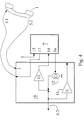
- Figure 4 shows a further embodiment of an inventive Device 18, which is used as an adapter for connecting an additional device 7 serves, but does not contain the additional device 7 itself.
- the components of the adapter and the additional device correspond to those in FIG. 2 shown and are designated by the same reference numerals.
- Adapters 18 can be any commercially available additional devices 7 simple terminal can be connected without it on the part of the Electronics of the additional device and the terminal of a modification requirement.
- the invention is particularly applicable in the field of telecommunications as a modified additional device or as an adapter for connecting a Additional device with which end devices already used are universal can be expanded, advantageously used commercially, which makes one broad customer base the use of new telecommunications features is opened.
Landscapes
- Engineering & Computer Science (AREA)
- Signal Processing (AREA)
- Telephone Function (AREA)
- Telephonic Communication Services (AREA)
- Data Exchanges In Wide-Area Networks (AREA)
- Mobile Radio Communication Systems (AREA)
Abstract
Description
Die Erfindung betrifft ein Verfahren zur Adaptierung von Zusatzeinrichtungen, wie Anrufbeantworter, Freisprecheinrichtungen, Wahlhilfen und dergleichen, an eine analoge Endeinrichtung für die Telekommunikation, insbesondere an ein Telefon. Die Erfindung betrifft weiterhin eine Vorrichtung zur Durchführung des Verfahrens.The invention relates to a method for adapting additional devices, such as answering machines, hands-free systems, dialing aids and the like, to an analog terminal for telecommunications, especially on a phone. The invention relates furthermore an apparatus for performing the method.
Telekommunikations-Endeinrichtungen, insbesondere einfache Telefone, sollen häufig durch Zusatzeinrichtungen, z.B. Anrufbeantworter, Freisprecheinrichtung, Wahlhilfen, aufgewertet werden. Dabei besteht die Notwendigkeit, einen gemeinsamen Anschluß für beide Einrichtungen unter Aufrechterhaltung der Funktionalität der Endeinrichtung zu schaffen, insbesondere wenn eine Zusatzeinrichtung, etwa eine Freisprecheinrichtung, in den Sprechweg der zu erweiternden Endeinrichtung eingefügt werden soll.Telecommunications terminal equipment, in particular simple telephones, are often to be replaced by additional devices, e.g. Answering machine, speakerphone, Election aids, be upgraded. There is the Need a common connection for both facilities while maintaining the functionality of the terminal equipment create, especially if an additional device, such as a Handsfree, in the speech path of the terminal to be expanded to be inserted.
Dazu ist es bekannt, direkt auf das zu erweiternde Endgerät Einfluß zu nehmen, indem entweder vorhandene Modifikationszusätze der Endgeräte genutzt oder aber, wenn diese nicht vorhanden sind, die interne Verdrahtung des Endgerätes entsprechend modifiziert wird. Der erste Lösungsansatz setzt voraus, daß das zu erweiternde Endgerät für Modifikationen für eine Zusatzeinrichtung vorbereitet ist. Dies ist insbesondere bei einfachen Analogtelefonen häufig nicht der Fall. Der zweite Lösungsansatz setzt voraus, daß der Benutzer des Endgeräts entweder selbst hinreichend technische Kenntnisse hat, um die interne Verschaltung des Endgeräts in geeigneter Weise zu ändern, oder aber bereit ist, einen entsprechenden Fachmann zu beauftragen.For this purpose, it is known to influence the terminal device to be expanded directly take by either existing modification additions of the terminals used or, if these are not available, the internal Wiring of the terminal is modified accordingly. The first Approach requires that the end device to be expanded for Modifications for an additional device is prepared. This is often not the case, especially with simple analog telephones. The second approach assumes that the user of the terminal either has sufficient technical knowledge to handle the internal Interconnection of the terminal in a suitable manner, or ready to change is to hire an appropriate specialist.
Der Erfindung liegt daher die Aufgabe zugrunde, ein Verfahren zur Adaptierung von Zusatzeinrichtungen an analoge Endeinrichtungen für die Telekommunikation, insbesondere in den Sprechweg der zu erweiternden Endeinrichtung eingreifenden Zusatzeinrichtungen, anzugeben, bei welchem Eingriffe in das zu erweiternde analoge Endgerät vermieden werden. Der Erfindung liegt weiterhin die Aufgabe zugrunde, eine Vorrichtung anzugeben, welche zur Aufrüstung von Endeinrichtungen mit Zusatzeinrichtungen universell einsetzbar ist.The invention is therefore based on the object of a method for Adaptation of additional devices to analog terminal devices for the Telecommunications, especially in the speech path of the to be expanded Additional equipment interfering with terminal equipment, to be specified at which interferes with the analog terminal to be expanded become. The invention is also based on the object Specify device which for upgrading terminal equipment with Additional devices can be used universally.
Die Aufgabe wird gelöst durch ein Verfahren zur Adaptierung von
Zusatzeinrichtungen an eine analoge Endeinrichtung für die Telekommunikation
gemäß Anspruch 1. Die Aufgabe wird weiterhin gelöst
durch eine Vorrichtung zur Durchführung des Verfahrens gemäß
Anspruch 6. Vorteilhafte Weiterbildungen des Verfahrens und der
Vorrichtung sind in den Unteransprüchen 2 bis 5 bzw. 7 bis 9 beschrieben.The task is solved by a method for the adaptation of
Additional devices to an analog terminal for telecommunications
according to
Die erfindungsgemäße Lösung beruht darauf, daß die Einfügung einer Zusatzeinrichtung in den Sprechweg eines analogen Endgerätes so erfolgt, daß die Betätigungsfunktionen, die für einen Verbindungsauf- bzw. -abbau erforderlich sind, in gewohnter Weise durchgeführt werden können und die elektrischen Bedingungen in Sicht auf das Telefonnetz unverändert bleiben.The solution according to the invention is based on the fact that the insertion of a Additional device in the speech path of an analog terminal is done in such a way that the actuation functions for a connection setup or clearing are required, can be carried out in the usual way and the electrical conditions in view of the telephone network remain unchanged.
Zu diesem Zweck werden erfindungsgemäß die mechanischen Funktionen, z.B. Eingabe von Wählbefehlen an einer Tastatur, von den Sprechfunktionen der Endeinrichtung getrennt, indem eine netzseitige Parallelschaltung des zu erweiternden analogen Endgerätes und der Zusatzeinrichtung unter Vermeidung einer Beeinflussung des standardisierten Leitungsabschlußwiderstands vorgenommen wird.For this purpose, according to the invention, the mechanical functions, e.g. Entering dialing commands on a keyboard, from the speech functions the terminal separated by a parallel network connection of the to be expanded analog terminal and the additional device under Avoid influencing the standardized line termination resistance is made.
Im einzelnen wird zur Abkopplung des ursprünglichen Sprechwegs von der Endeinrichtung zunächst auf deren Netzzugangsleitung hochohmig zugegriffen, wobei der standardisierte Leitungsabschlußwiderstand erhalten bleibt. Das abgegriffene Signal ist vorzugsweise proportional zum Sprachsignal, welches aus dem Telefonnetz kommend an das Endgerät übertragen wird. Das über die Netzzugangsleitung direkt zum Endgerät übertragene Sprachsignal wird im Gegensatz zur normalen Funktionsweise des Endgerätes bei der vorliegenden Erfindung nicht weiter zur Realisierung der Sprechfunktion verwertet.In particular, the original speech path is decoupled from the Terminal device with high impedance on its network access line accessed, receiving the standardized line termination resistance remains. The tapped signal is preferably proportional to Speech signal coming from the telephone network to the terminal is transmitted. This via the network access line directly to the end device transmitted voice signal is in contrast to normal functioning of the terminal in the present invention no further Realization of the speech function exploited.
Der ursprüngliche Sprechweg und die Spracheingabe- und -ausgabeeinheit der Endeinrichtung, insbesondere der Telefonhörer, bleibt vielmehr ungenutzt. Der Telefonhörer kann entfernt werden. The original speech path and voice input and output device the terminal device, in particular the telephone handset, rather remains unused. The telephone handset can be removed.
Zur Realisierung eines neuen Sprechwegs, in welchem sich die Zustzeinrichtung problemlos einfügen läßt, wird nun das von der Netzzugangsleitung hochohmig abgegriffenen Sprachsignal oder ein dazu proportionales Signal an die Zusatzeinrichtung und an eine von der Endeinrichtung elektrisch getrennte Spracheingabe- und -ausgabeeinheit geführt. Vorzugsweise wird das abgegriffene Sprachsignal vor dem Einkoppeln in die Zusatzeinrichtung bzw. die Spracheingabe- und -ausgabeeinheit verstärkt, um es etwa auf den Signalpegel zu bringen, den das über die Netzzugangsleitung übertragenen Signal aufweist.To implement a new speech path in which the additional device is located can be inserted without any problems, this is now from the network access line high-impedance tapped speech signal or one proportional signal to the additional device and to one of the Terminal device electrically separated voice input and output unit guided. The tapped speech signal is preferably used before coupling in the additional device or the voice input and output unit amplified to bring it up to about the signal level that the above the network access line has transmitted signal.
Somit werden "kommende" Sprachsignale, also solche, die über das Telefonnetz an die Endeinrichtung übermittelt werden, an die Zusatzeinrichtung sowie an eine Sprachausgabeeinheit, wie einen Lautsprecher, geleitet. Der Benutzer kann in bekannter Weise das in ein akustisches Signal umgesetzte Sprachsignal hören. Zusätzlich kann die Zusatzeinrichtung die Sprachsignale aufzeichnen oder sonstwie auf sie Einfluß nehmen, sie z.B. als Freisprecheinrichtung laut wiedergeben.Thus, "coming" speech signals, that is, those that are transmitted via the Telephone network to be transmitted to the terminal, to the additional device as well as to a speech output unit, such as a loudspeaker, headed. The user can do this in a known manner in an acoustic Hear the converted voice signal. In addition, the additional device record the voice signals or otherwise influence them take them e.g. Play loudly as a speakerphone.
Die "gehenden" Signale, also die vom Benutzer in der Regel akustisch eingegebenen und zur Ubertragung über das Telefonnetz in ein elektronisches Signal umgewandelten Sprachsignale, werden bei der Erfindung an einer Spracheingabeeinheit eingegeben, welche ebenfalls vom aufzurüstenden Endgerät elektrisch getrennt ist. Der ursprüngliche Sprechweg des Endgerätes bleibt erfindungsgemäß auch zur Eingabe von Sprachsignalen ungenutzt. Das aufzurüstende Endgerät kann jedoch jederzeit auch ohne Zusatzeinrichung funktionieren, d.h. der urspüngliche Sprechweg wird nicht vollständig deaktiviert oder unterbrochen. Neben der Spracheingabeeinheit oder alternativ dazu erzeugt die Zusatzeinrichtung ein Ausgangssignal, welches in der Regel ebenfalls gesprochener Sprache entspricht, z.B. einen Ansagetext.The "outgoing" signals, that is to say those which are generally entered acoustically by the user and for transmission over the telephone network into an electronic one Signal-converted speech signals are in the invention on a Voice input unit entered, which is also from the upgraded Terminal is electrically isolated. The original speech path of the end device remains unused according to the invention also for the input of voice signals. However, the device to be upgraded can also be used at any time Additional devices work, i.e. the original speech path becomes not completely disabled or interrupted. In addition to the Voice input unit or alternatively generates the additional device an output signal, which is usually also spoken language corresponds, e.g. an announcement.
Das Ausgangssignal der Spracheingabeeinheit und/oder der Zusatzeinrichtung wird dann unter Erhalt des Leitungsabschlußwiderstands hochohmig in die Netzzugangsleitung des aufzurüstenden Endgerätes eingekoppelt. Vorzugsweise wird dazu eine spannungsgesteuerte Stromquelle verwendet. Dabei dient das Ausgangssignal von Spracheingabeeinheit und/oder Zusatzeinrichtung zur Steuerung des Stromflusses der Stromquelle, deren Ausgang mit der Netzzugangsleitung verbunden ist. The output signal of the voice input unit and / or the additional device then becomes high-resistance while maintaining the line termination resistance coupled into the network access line of the terminal to be upgraded. For this purpose, a voltage-controlled current source is preferred used. The output signal from the voice input unit is used and / or additional device for controlling the current flow of the current source, the output of which is connected to the network access line.
Auf diese Weise werden somit auch gehende Signale, die sowohl direkt vom Benutzer bzw. der Spracheingabeeinheit als auch von der Zusatzeinrichtung erzeugt werden als Sprachsignal in die Netzzugangsleitung eingekoppelt und über das Telefonnetz übertragen.In this way, outgoing signals that are both directly from the User or the voice input unit as well as from the additional device generated are coupled into the network access line as a voice signal and transmitted over the telephone network.
Zur Ausübung der Wähl- und sonstigen Steuerfunktionalitäten wird weiterhin das Endgerät verwendet. Die Wähl- und Steuersignale werden in bekannter Weise vom Endgerät durch Tastatureingabe oder dergleichen erzeugt und direkt über die Netzzugangsleitung an das Telefonnetz weitergeleitet. Ebenso erreichen Wähl- und Steuersignale, die von der Vermittlungsstelle erzeugt wurden, das Endgerät unmittelbar über die Netzzugangsleitung. Dadurch ist gewährleistet, daß der Benutzer das Endgerät in üblicher Weise weiterverwenden kann. Es sind keine Modifikationen der Steuerung des Endgerätes notwendig.The exercise of dialing and other tax functions will continue used the terminal. The selection and control signals are in known manner from the terminal by keyboard input or the like generated and directly via the network access line to the telephone network forwarded. Likewise, dialing and control signals reach from the Switch were generated, the terminal directly over the Network access line. This ensures that the user Can continue to use the terminal in the usual way. They are not modifications the control of the terminal is necessary.
In einer vorteilhaften Weiterbildung der Erfindung wird die Zusatzeinrichtung und/oder die Spracheingabe- und -ausgabeeinheit in Unabhängigkeit von der Aktivität des Endgerätes funktionell zu- bzw. abgeschaltet. Dazu wird der Spannungspegel auf der Netzzugangsleitung gemessen und die Zusatzeinrichtung und/oder die Spracheingabe- und -ausgabeeinheit in Abhängigkeit davon aktiviert bzw. deaktiviert. Die Messung des Spannungspegels auf der Netzzugangsleitung wird beispielsweise mit einem Komparator vorgenommen, der auf die Netzzugangsleitung zugreift und ein Ausgangssignal liefert, wenn der Spannungspegel eine vorbestimmte Schallschwelle über- bzw. unterschreitet. Dieses Schaltsignal dient dazu, die Zusatzeinrichtung und/oder die Spracheingabe- und -ausgabeeinheit an- bzw. abzuschalten.In an advantageous development of the invention, the additional device and / or the voice input and output unit in independence functionally switched on or off by the activity of the terminal. For this, the voltage level on the network access line measured and the additional device and / or the voice input and output unit activated or deactivated depending on this. The Measurement of the voltage level on the network access line is, for example made with a comparator on the network access line accesses and provides an output signal when the voltage level exceeds or falls below a predetermined sound threshold. This switching signal serves the additional device and / or the voice input and - Switch output unit on or off.
In einer weiteren Ausprägung der Erfindung kann die Aktivitätenermittlung auch zu einer wirtschaftlichen Abschaltung der Gesamtstromversorgung herangezogen werden.In a further embodiment of the invention, the activity can be determined also to an economic shutdown of the total power supply be used.
- Figur 1Figure 1
- eine Endeinrichtung für die Telekommunikation, welche mit einer Vorrichtung zur Durchführung des erfindungsgemäßen Verfahrens aufgerüstet ist;a terminal for telecommunications, which with a device for performing the invention Procedure is upgraded;
- Figur 2Figure 2
- ein Prinzipschaltbild eines Systems aus Endeinrichtung und erfindungsgemäßer Vorrichtung;a schematic diagram of a system of terminal equipment and device according to the invention;
- Figur 3Figure 3
- die prinzipielle Signalführung innerhalb der Zusatzeinrichung; the basic signal routing within the additional device;
- Figur 4Figure 4
- eine erfindungsgemäße Vorrichtung, die als Adapter zum Anschluß einer Zusatzeinrichtung dient.an inventive device that as an adapter for Connection of an additional device is used.
In Figur 1 ist ein analoges Endgerät für die Telekommunikation in Verbindung
mit einer Vorrichtung 18 zur Adaptierung von Zusatzeinrichtungen
dargestellt. Die Zusatzeinrichtung selbst ist gemäß Figur 2 in die Vorrichtung
18 integriert und hier nicht gezeigt.In Figure 1, an analog terminal for telecommunications is connected
with a
Das Endgerät 4 weist eine Hörerauflage 2 auf, auf welcher üblicherweise der
Telefonhörer 1 als Spracheingabe- und -ausgabeeinheit des Endgerätes 4
aufliegt. Ein mechanisches Betätigen der Hörerauflage 2, insbesondere
durch Auflegen bzw. Abnehmen des Hörers, bewirkt ein Öffnen bzw.
Schließen der Gabelschaltung 3, welche im Endgerät 4 integriert ist. Durch
die Gabelschaltung 3 ist der elektrische Kontakt zum Telefonnetz über die
Netzzugangsleitung 6, mit den hier dargestellten Komponenten 6.1 und 6.2
herstellbar.The
Über die Netzanschlußleitung 6 werden üblicherweise die an einer
Wähleinheit, z.B. einer Tastatur, eingegebenen Wählbefehle sowie die am
Telefonhörer eingegebenen Sprachsignale als elektronisches Signal an das
Telefonnetz und zum Kommunikationspartner übertragen. Zur Übertragung
von Sprachsignalen ist daher der Telefonhörer 1 eines Standard-Endgerätes
über einen Anschluß 20 am Endgerät direkt mit dem Endgerät
und den darin befindlichen Komponenten, insbesondere einer Wandlerschaltung
9 und der Netzzugangsleitung 6 verbunden. Am Telefonhörer
eingegebene Signale werden somit direkt auf die Netzzugangsleitung 6
gegeben.About the
Erfindungsgemäß ist das Endgerät jedoch in diesem Punkt abgewandelt:
Der Telefonhörer 1 ist über die Anschlußleitung 5 nicht mit dem Anschluß
20 am Endgerät, sondern mit einer Schnittstelle 19 an der erfindungsgemäßen
Vorrichtung 18 verbunden. Um dies zu realisieren, kann der
ursprünglich am Endgerät 4 vorhandene Telefonhörer entfernt und an die
Vorrichtung 18 an der Schnittstelle 19 angeschlossen werden. Alternativ
dazu ist es möglich, den am Endgerät 4 vorhandene Telefonhörer nicht zu
nutzen und statt dessen eine Spracheingabe- und -ausgabeeinheit, die von
vorneherein mit der Vorrichtung 18 gekoppelt ist, auf die Hörerauflage 2 des
aufzurüstenden Endgerätes 4 aufzulegen. Wesentlich ist, daß Spracheingaben
an einer Spracheingabeeinheit 1 erfolgen, welche direkt elektronisch
mit der Vorrichtung 18 gekoppelt sind. Die Spracheingabeeinheit ist
beispwielsweise die Sprechmuschel eines Hörers mitsamt dazugehöriger
Elektronik oder das Mikrofon einer Freisprecheinrichtung. Die
Sprachausgabeeinheit ist die Hörmuschel eines Hörers oder der
Lautsprecher einer FreisprecheinrichtungAccording to the invention, however, the terminal is modified on this point:
The
Im Gegensatz zur Einsatzweise eines herkömmlichen Endgerätes ist der
Netzanschluß des Endgerätes 4 bei dem hier dargestellten Beispiel nicht
direkt mit dem Telefonnetz verbunden, sondern als Netzanschlußleitung 6.1
zunächst mit der Vorrichtung 18. Die Herstellung der Verbindung zwischen
Endgerät 4 und Vorrichtung 18 erfolgt über eine erste Schnittstelle 8, welche
z.B. eine analoge a/b-Schnittstelle ist. Der Netzzugang des Endgeräts 4 zum
Telefonnetz wird über die Netzzugangsleitung 6.1 des Endgerätes und die
Netzzugangsleitung 6.2 der Vorrichtung 18 hergestellt, indem die erste
Schnittstelle 8 innerhalb der Vorrichtung 18 mit der Netzanschlußleitung
6.2 gekoppelt ist, siehe Figur 2. Die gesamte Netzzugangsleitung 6 wird
somit durch die Vorrichtung 18 durchgeschleift, wobei erfindungsgemäß
innerhalb der Vorrichtung auf die Netzzugangsleitung zugegriffen wird.In contrast to the use of a conventional terminal, the
Mains connection of the
Zur Adaptierung von Zusatzeinrichtungen an eine analoge Endeinrichtung
4 wird die Vorrichtung 18 mittels der Netzzugangsleitung 6.2 an das
Telefonnetz angeschlossen. Die Vorrichtung 18 wird mit einer Spracheingabe- und -ausgabeeinheit 1 ausgestattet, falls eine solche nicht bereits
Bestandteil der Vorrichtung 18 ist. Diese Spracheingabe- und -ausgabeeinheit
1, hier ein Telefonhörer, wird auf die Hörerauflage 2 des Endgerätes
aufgelegt, wobei der ursprünglich dem Endgerät zugeordnete Hörer von der
Hörerauflage entfernt wird. Ein mechanisches Abkoppeln des ursprünglich
vorhandenen Hörers ist nicht notwendig. Weiterhin wird die Netzzugangsleitung
6.1 der Endeinrichtung 4 über die erste Schnittstelle 8 mit der
Vorrichtung 18 verbunden.For adapting additional devices to an
Zur genaueren Beschreibung der Funktionsweise der Erfindung wird das
Blockdiagramm der Figur 2 herangezogen. Im oberen Teil der Figur 2 sind
die die Erfindung betreffenden Komponenten eines Standardendgerätes 4
dargestellt. Der untere Teil der Figur 2 zeigt den prinzipiellen Aufbau der
Vorrichtung 18 zur Adaptierung von Zusatzeinrichtungen, wobei die
Zusatzeinrichtung 7 in die Vorrichtung 18 integriert ist. For a more detailed description of the operation of the invention, the
Block diagram of Figure 2 used. In the upper part of Figure 2 are
the components of a
Die die Erfindung betreffenden Komponenten eines Standardtelefons 4 sind
der Telefonhörer 1', die Gabelschaltung 3, der Leitungsabschlußwiderstand
10 und die 2-Draht/4-Draht-Wandlung 9. Der Telefonhörer 1' ist über einen
Anschluß 20 und eine entsprechende Anschlußleitung an das Endgerät 4
angeschlossen. Erfindungsgemäß wird der Telefonhörer 1' des Endgerätes 4
jedoch nicht verwendet; der ursprüngliche Sprechweg des Endgerätes 4
bleibt ungenutzt. Statt dem Standard-Telefonhörer 1' befindet sich der Hörer
1 der Vorrichtung 18 im Ruhezustand auf der Hörerauflage 2, wie in Figur 1
dargestellt.The components of a
Endgerät 4 und Vorrichtung 18 sind über die Netzanschlußleitung 6.1 des
Endgerätes 4 miteinander verbunden. Dazu ist die Netzanschlußleitung 6.1,
welche im Standardfall direkt mit einer Netzanschlußbuchse verbunden ist,
zunächst über eine erste Schnittstelle 8 mit einer im Inneren der
Vorrichtung 18 verlaufenden Netzzugangsleitungsstück 6.3 verbunden,
welches als Netzzugangsleitung 6.2 der Vorrichtung 18 herausgeführt ist.
Das Leitungsstück 6.2 bildet die Netzzugangsleitung der Vorrichtung, mit
welcher sie an ein Telefonnetz anschließbar ist. Die drei Leitungselemente
6.1, 6.3 und 6.2 bilden im Anwendungsfall die Netzzugangsleitung des
Endgerätes 4, über welche Signalisierungssignale, wie Wähl- und sonstige
Steuerzeichen, vom Endgerät über die Vorrichtung 18 zum Telefonnetz und
umgekehrt übertragbar sind.Terminal 4 and
Endgerät 4 und Vorrichtung 18 sind also auf zwei Weisen gekoppelt:
Zum einen besteht eine Kopplung auf elektrischem Weg, indem die Netzzugangsleitung
des Endgerätes durch die Vorrichtung 18 durchgeschleift
ist, wobei Sprachsignale innerhalb der Vorrichtung 18 aus- bzw. eingekoppelt
werden. Zum anderen besteht eine Kopplung zwischen End- und
Zusatzeinrichtung, indem die Spracheingabe- und -ausgabeeinheit 1 mit der
Vorrichtung 18 über eine Anschlußleitung 5 (5.1, 5.2) elektrisch und mit
dem Endgerät 4 durch Auflage auf dessen Hörerauflage mechanisch
gekoppelt ist. Die mechanische Kopplung, durch welche die Gabelschaltung
3 betätigbar ist, ist in Figur 2 durch eine gestrichelte Linie vom Telefonhörer
1 zur Gabelschaltung 3 angedeutet.Terminal 4 and
Der Verbindungsaufbau beginnt bei einfachen Endgeräten 4 damit, daß der
Telefonhörer 1 abgehoben wird. Dies bewirkt zunächst ein mechanisches
Schließen des Gabelkontaktes 3 über die Hörerauflage 2, womit auch
elektrisch die Verbindung zu einem Amt oder einer Nebenstellenanlage
über die Netzanschlußleitung 6 herbeigeführt wird. Über die Netzanschlußleitung
erhält das Telefon auch eine Speisung mit elektrischer
Energie, die für die Funktion des Telefons selbst erforderlich ist.The connection establishment begins with
Infolge der elektrischen Belastung (Gleichstrom) sinkt die Leerlaufspannung
auf der Netzanschlußleitung 6 auf einen deutlich geringeren
Wert ab. Die Leerlaufspannung beträgt üblicherweise ca. 24 bis 70 V. Bei
geschlossener Gabelschaltung, d.h. aktiviertem Endgerät 4, beträgt die
Spannung etwa 8 bis 12 V.As a result of the electrical load (direct current), the open circuit voltage drops
on the
An einer Wähleinheit, z.B. einer Tastatur gibt der Nutzer des Endgerätes 4
Wählbefehle ein, welche in elektrische Signale umgesetzt werden, die über
die Netzanschlußleitung 6 übertragen werden.On a dialing unit, e.g. the user of the
Nach erfolgreicher Verbindungsherstellung treten die Sprechwege in
Aktion. Zunächst muß die Netzanschlußleitung auf seiten des Endgerätes
mit einem standardisierten Leitungswiderstand 10 (Wechselstrom) abgeschlossen
sein. Dies wird beim Standard-Endgerät bereits beim Schließen
des Gabelkontaktes 3 ausgeführt. Das über die Netzanschlußleitung 6 (6.2,
6.3, 6.1) übertragene kommende Sprachsignal wird mittels des Wandlers 9
zum Lautsprecher des Telefonhörers 1' geleitet, das am Mikrofon des
Telefonhörers 1' eingegebene Sprachsignal wird mittels des Wandlers 9 in
die Netzanschlußleitung eingekoppelt. Dieser Standard-Sprechweg mit dem
Telefonhörer 1' als Schnittstelle zum Benutzer bleibt bei der vorliegenden
Erfindung ungenutzt, aber prinzipiell funktionsfähig. Stattdessen werden
Sprachsignale, die aus dem Telefonnetz kommen, über die
Netzanschlußleitung 6.2 an die Vorrichtung 18 und dann über die
Leitungselemente 6.3 und 6.1 an das Endgerät übertragen werden,
innerhalb der Vorrichtung 18 abgegriffen. Sie werden der
Zusatzeinrichtung 7 sowie an den Lautsprecher der Spracheingabe- und
-ausgabeeinheit 1, die an die Vorrichtung 18 angeschlossen ist, weitergeleitet.
Umgekehrt werden an der Spracheingabe- und -ausgabeeinheit 1
eingegebene akustische Signale in elektrische Sprachsignale umgewandelt,
über die Leitung 5.2 zur Vorrichtung 18 und zur Zusatzeinrichtung 7
übertragen sowie innerhalb der Vorrichtung in die Netzanschlußleitung 6
eingekoppelt. Auf diese Weise ist der Sprechweg des Endgerätes über die
Vorrichtung 18 geführt, wobei eine Zusatzeinrichtung 7 in den Sprechweg
integriert wurde, siehe Fig. 3. Die übrigen Funktionen des analogen
Endgerätes 4, insbesondere die Steuerung durch Tastatureingaben und
dergleichen, sind durch das Abkoppeln des Sprechwegs mittels der
Vorrichtung 18 nicht beeinträchtigt, denn diese Signalisierungssignale
werden nach wie vor über die Netzanschlußleitung 6, bestehend aus den
Elementen 6.1, 6.3 und 6.2, übertragen.After the connection has been successfully established, the speech paths begin
Action. First, the power cord on the end device side
terminated with a standardized line resistance 10 (alternating current)
his. With the standard terminal, this is already the case when it is closed
the fork contact 3 executed. The network line 6 (6.2,
6.3, 6.1) transmitted voice signal is transmitted by means of the converter 9
to the speaker of the telephone handset 1 ', which is connected to the microphone of the
Telephone handset 1 'entered voice signal is converted by the converter 9 in
the power cord is coupled. This standard speech path with the
Telephone receiver 1 'as the interface to the user remains with the present
Invention unused, but in principle functional. Instead be
Voice signals that come from the telephone network, over the
Power cord 6.2 to the
Zur Konstanthaltung der elektrischen Bedingungen aus Sicht des
Telefonnetzes ist es notwendig, daß der Leitungsabschlußwiderstand 10
durch die zusätzliche Beschaltung nicht verfälscht wird. Der Leitungsabschlußwiderstand
der Gesamtvorrichtung darf daher nicht wesentlich
vom Wert des Leitungsabschlußwiderstands 10 abweichen. Aus diesem
Grund wird das kommende Signal über einen hochohmigen Verstärker 13
von der Netzüberleitung 6 abgegriffen, der Eingangswiderstand des
Verstärkers ist im Idealfall unendlich, in der Praxis sollte er größer als 600
Ohm sein. Das Ausgangssignal des Verstärkers 13 wird einem ersten
Eingang 14 der Zusatzeinrichtung 7 zugeführt. Ebenso muß das gehende
Signal, das der erste Ausgang 16 der Zusatzeinrichtung 7 bereitstellt,
hochohmig an die Netzzuführung 6 eingespeist werden. Erfindungsgemäß
erfolgt dies durch eine spannungsgesteuerte Stromquelle 12. Das
Ausgangssignal der Stromquelle wird durch das Signal am Ausgang 16 der
Zusatzeinrichtung gesteuert und in die Netzzugangsleitung eingespeist.To keep the electrical conditions constant from the point of view of the
Telephone network, it is necessary that the
Die Funktion des Wandlers 9 des Endgeräts wird nunmehr von den
Elementen 12 und 13 wahrgenommen.The function of the converter 9 of the terminal is now from
Das Signal wird einerseits von der Zusatzeinrichtung 7 weiterverarbeitet,
z.B. gespeichert oder verstärkt widergegeben. Andererseits wird es über
einen zweiten Ausgang 17 der Zusatzeinrichtung 7 und die Anschlußleitung
5.1 an den Lautsprecher der Spracheingabe- und -ausgabeeinheit 1 geleitet.
Das gehende, vom Benutzer erzeugte Sprachsignal wird der
Zusatzeinrichtung 7 über einen zweiten Eingang 15, welcher über eine
Leitung 5.2 mit dem Mikrofon der Spracheingabe- und -ausgabeeinheit
verbunden ist, zugeführt und kann über den Ausgang 16 in die Netzzugangsleitung
eingekoppelt werden. Ebenso kann das von der Zusatzeinrichtung
7 erzeugte Signal, z.B. eine Textansage eines Anrufbeantworters,
über den Ausgang 16 ausgegeben und gleichfalls in die Netzzugangsleitung
6 eingekoppelt werden.The signal is processed on the one hand by the
Die Signalwege innerhalb der Zusatzeinrichtung 7 sind im einzelnen in
Figur 3 dargestellt. Das von der Zusatzeinrichtung 7 bzw. deren Digitalfilter
erzeugte Signal wird mit dem Signal der Spracheingabe-/-ausgabeeinheit
zusammengeführt. Falls die Zusatzeinrichtung eine Freisprecheinrichtung
ist, kann zusätzlich eine Raumechaunterdrückung vorgesehen sein, hier
skizziert durch das Bauelement LMS.The signal paths within the
Somit können die zusätzlichen Funktionen der Zusatzeinrichtung realisiert
werden, während die Sprechfunktion und die Betätigungsfunktionen der
Gesamtanordnung gewährleistet sind. Die Sprechwege der Spracheingabe- und
-ausgabeeinheit 1 und der Zusatzeinrichtung 7 sind parallel geschaltet.The additional functions of the additional device can thus be implemented
be while the speech function and the actuation functions of the
Overall arrangement are guaranteed. The speech paths of voice input and
Um zu verhindern, daß bei einer nicht aufgebauten Verbindung Signale
vom Netz oder in das Netz gespeist werden, wird in einer vorteilhaften
Weiterbildung der Erfindung eine Aktivitätserkennung vorgenommen, die
das Zu- bzw. Abschalten der Zusatzeinrichtung 7 veranlaßt. Die Aktivität auf
der Netzzugangsleitung 6 wird durch eine Messung der Gleichspannung
auf der Zugangsleitung 6 mittels eines Komparators 11 ermittelt. Der
Komparator 11 greift auf die Netzzugangsleitung 6 zu und gibt ein
Ausgangssignal ab, wenn der Spannungspegel eine vorbestimmte
Schallschwelle über- bzw. unterschreitet. Der Schwellwert ist dabei so
gewählt, daß er zwischen der Leerlaufspannung sowie der Spannung bei
Belastung liegt, so daß ein Wechsel zwischen beiden Zuständen sicher erfaßt
werden kann. Der Komparator 11 gibt ein Ausgangssignal, welches den
Betriebszustand der Endeinrichtung 4 anzeigt, also im wesentlichen, ob die
Gabelschaltung 3 offen oder geschlossen ist. Das Ausgangssignal des
Komparators 11 dient zur Steuerung des Betriebszustandes der Zusatzeinrichtung
7 und/oder der Spracheingabe- und -ausgabeeinheit 1, vorzugsweise
von beiden.To prevent signals when the connection is not established
fed from the grid or into the grid will be beneficial
Development of the invention carried out an activity detection
the switching on or off of the
Figur 4 zeigt als weiteres Ausführungsbeispiel eine erfindungsgemäße
Vorrichtung 18, die als Adapter zum Anschluß einer Zusatzeinrichtung 7
dient, die Zusatzeinrichtung 7 jedoch nicht selbst enthält. Die Komponenten
des Adapters und der Zusatzeinrichtung entsprechen den in Fig. 2
dargestellten und sind mit denselben Bezugsziffern bezeichnet. Mit dem
Adapter 18 können beliebige handelsübliche Zusatzeinrichungen 7 an ein
einfaches Endgerät angeschlossen werden, ohne daß es auf seiten der
Elektronik der Zusatzeinrichtung und des Endgeräts einer Modifikation
bedarf. Figure 4 shows a further embodiment of an
Die Erfindung läßt sich im Bereich der Telekommunikation insbesondere als modifiziertes Zusatzgerät oder als Adapter zum Anschluß eines Zusatzgerätes, mit welchem bereits eingesetzte Endgeräte universell erweitert werden können, vorteilhaft gewerblich anwenden, wodurch einem breiten Kundenkreis die Nutzung neuer Telekommunikations-Merkmale eröffnet wird. The invention is particularly applicable in the field of telecommunications as a modified additional device or as an adapter for connecting a Additional device with which end devices already used are universal can be expanded, advantageously used commercially, which makes one broad customer base the use of new telecommunications features is opened.
- 1, 1'1, 1 '
- Spracheingabe- und -ausgabeeinheit (Telefonhörer)Voice input and output unit (telephone handset)
- 22nd
- HörerauflageHandset rest
- 33rd
- GabelschaltungHybrid
- 44th
- EndeinrichtungTerminal equipment
- 55
- Anschlußkabel (Telefonhörer)Connection cable (telephone handset)
- 6, 6.1, 6.2, 6.36, 6.1, 6.2, 6.3
- NetzzugangsleitungNetwork access line
- 77
- ZusatzeinrichtungAdditional device
- 88th
- erste Schnittstelle (Anschluß für Endeinrichtung)first interface (connection for terminal equipment)
- 99
- WandlerConverter
- 1010th
- LeitungsabschlußwiderstandLine termination resistor
- 1111
- KomparatorComparator
- 1212th
- spannungsgesteuerte Stromquellevoltage controlled current source
- 1313
- hochohmiger Verstärkerhigh impedance amplifier
- 1414
- erster Eingang (Zusatzeinrichtung)first entrance (additional equipment)
- 1515
- zweiter Eingang (Zusatzeinrichtung)second entrance (additional device)
- 1616
- erster Ausgang (Zusatzeinrichtung)first output (additional device)
- 1717th
- zweiter Ausgang (Zusatzeinrichtung)second output (additional device)
- 1818th
- Vorrichtung zur Adaptierung von ZusatzeinrichtungenDevice for adapting additional devices
- 1919th
- zweite Schnittstelle (Telefonhörer)second interface (telephone handset)
- 2020th
- Anschluß für Telefonhörer (Endgerät)Connection for telephone handset (end device)
Claims (9)
daß der Betriebszustand der Zusatzeinrichtung und/oder die Spracheingabe- und -ausgabeeinheit an den Betriebszustand der Endeinrichtung angepaßt wird, indem der Spannungspegel auf der Netzzugangsleitung gemessen und die Zusatzeinrichtung und/oder die Spracheingabe- und -ausgabeeinheit in Abhängigkeit vom Spannungspegel aktiviert bzw. deaktiviert wird.A method according to claim 1, characterized in
that the operating state of the additional device and / or the voice input and output unit is adapted to the operating state of the terminal device by measuring the voltage level on the network access line and activating or deactivating the additional device and / or the voice input and output unit as a function of the voltage level .
daß die Zusatzeinrichtung und/oder die Spracheingabe- und -ausgabeeinheit aktiviert wird, wenn der Spannungspegel auf der Netzzugangsleitung eine vorbestimmte Schaltschwelle über- oder unterschreitet.A method according to claim 2, characterized in
that the additional device and / or the voice input and output unit is activated when the voltage level on the network access line exceeds or falls below a predetermined switching threshold.
daß das abgegriffene Sprachsignal vor dem Einkoppeln in die Zusatzeinrichtung bzw. die Spracheingabe- und -ausgabeeinheit verstärkt wird.Method according to one of the preceding claims, characterized in that
that the tapped voice signal is amplified before being coupled into the additional device or the voice input and output unit.
daß das abgegriffene Sprachsignal auf einen ersten Eingangskanal (14) der Zusatzeinrichtung und über einen ersten Ausgangskanal (16) der Zusatzeinrichtung auf den Eingang (5.1) der Spracheingabe- und -ausgabeeinheit geführt wird sowie das Ausgangssignal der Spracheingabe- und -ausgabeeinheit auf einen zweiten Eingangskanal (15) der Zusatzeinrichtung und geführt und über einen zweiten Ausgangskanal (16) der Zusatzeinrichtung in die Netzzugangsleitung eingekoppelt wird.Method according to one of the preceding claims, characterized in that
that the tapped speech signal is routed to a first input channel (14) of the additional device and via a first output channel (16) of the additional device to the input (5.1) of the voice input and output unit and the output signal of the voice input and output unit to a second input channel (15) of the additional device and is guided and coupled into the network access line via a second output channel (16) of the additional device.
daß sie einen Komparator (11) umfaßt, der auf die Netzzugangsleitung der Vorrichtung zugreift und ein vom Spannungspegel abhängiges Schaltsignal abgibt, welches die Zusatzeinrichtung (7) zu aktivieren oder zu deaktivieren imstande ist.Apparatus according to claim 6, characterized in
that it comprises a comparator (11) which accesses the mains access line of the device and emits a switching signal which is dependent on the voltage level and which is capable of activating or deactivating the additional device (7).
daß die Spracheingabe- und -ausgabeeinheit (1) der Vorrichtung ein Telefonhörer und/oder eine Freisprecheinrichtung ist.Device according to claim 6 or 7, characterized in that
that the voice input and output unit (1) of the device is a telephone handset and / or a hands-free device.
daß sie eine spannungsgesteuerte Stromquelle (12) umfaßt zur hochohmigen Einkopplung des Ausgangssignals der Zusatzeinrichtung (7) und/oder der Spracheingabe- und -ausgabeeinheit (1) in die Netzzugangsleitung.Device according to one of claims 6 to 8, characterized in that
that it includes a voltage-controlled current source (12) for high-resistance coupling of the output signal of the additional device (7) and / or the voice input and output unit (1) into the network access line.
Applications Claiming Priority (2)
| Application Number | Priority Date | Filing Date | Title |
|---|---|---|---|
| DE19832664A DE19832664A1 (en) | 1998-07-21 | 1998-07-21 | Method for adapting additional devices to an analog terminal device for telecommunications and device therefor |
| DE19832664 | 1998-07-21 |
Publications (3)
| Publication Number | Publication Date |
|---|---|
| EP0975129A2 true EP0975129A2 (en) | 2000-01-26 |
| EP0975129A3 EP0975129A3 (en) | 2003-12-10 |
| EP0975129B1 EP0975129B1 (en) | 2006-03-08 |
Family
ID=7874736
Family Applications (1)
| Application Number | Title | Priority Date | Filing Date |
|---|---|---|---|
| EP99110117A Expired - Lifetime EP0975129B1 (en) | 1998-07-21 | 1999-05-25 | Device and method for adapting accessory apparatuses to an analog telecommunication terminal |
Country Status (5)
| Country | Link |
|---|---|
| US (1) | US6636601B1 (en) |
| EP (1) | EP0975129B1 (en) |
| JP (1) | JP2000078244A (en) |
| AT (1) | ATE320136T1 (en) |
| DE (2) | DE19832664A1 (en) |
Cited By (1)
| Publication number | Priority date | Publication date | Assignee | Title |
|---|---|---|---|---|
| EP1294160A2 (en) * | 2001-09-14 | 2003-03-19 | Mitel Knowledge Corporation | Signaling system |
Families Citing this family (1)
| Publication number | Priority date | Publication date | Assignee | Title |
|---|---|---|---|---|
| CN101909124B (en) * | 2009-06-08 | 2012-07-04 | 亚旭电脑股份有限公司 | Network telephone |
Citations (5)
| Publication number | Priority date | Publication date | Assignee | Title |
|---|---|---|---|---|
| US5206898A (en) * | 1989-05-26 | 1993-04-27 | Shirohato Yakuhiin Co., Ltd. | Transmission control unit |
| EP0559948A2 (en) * | 1992-03-07 | 1993-09-15 | Bundesrepublik Deutschland, vertr. durch Vorstand der D. Bundespost TELEKOM, vertr. durch Präs. des Fernmeldetechn. Z.amtes | Device for connecting accessory apparatus to a telephone set |
| US5455859A (en) * | 1994-11-28 | 1995-10-03 | Gutzmer; Howard A. | Telephone handset interface for device having audio input |
| US5473676A (en) * | 1990-09-27 | 1995-12-05 | Radish Communications Systems, Inc. | Telephone handset interface for automatic switching between voice and data communications |
| US5625679A (en) * | 1996-04-23 | 1997-04-29 | Gutzmer Enterprises, Ltd. | Telephone handset interface for alternating voice-data (AVD) modem |
Family Cites Families (6)
| Publication number | Priority date | Publication date | Assignee | Title |
|---|---|---|---|---|
| US5151972A (en) * | 1989-03-28 | 1992-09-29 | Lynx Automation, Inc. | Apparatus for automatically connecting terminal device to telephone lines |
| DE4206933A1 (en) * | 1992-03-05 | 1993-09-09 | Teleint Ges Fuer Computer Und | Combined telephone and data or facsimile transmission modem |
| JPH08298585A (en) * | 1995-04-26 | 1996-11-12 | Oki Data:Kk | Switch controller of communication terminal |
| DE19529200A1 (en) * | 1995-08-09 | 1997-02-13 | Grundig Emv | Automatic engaged condition recognition method esp. for telecommunication line - using comparator with variable reference provided by controller which is responsive to position of hook switch, to compare supply voltage on exchange line with reference voltage from control unit |
| DE19606148A1 (en) * | 1996-02-16 | 1997-09-11 | Insys Gmbh | Telephone line circuit for operating data or information communications equipment |
| US5912948A (en) * | 1996-12-10 | 1999-06-15 | Vertizon Corporation | Automatic screening apparatus and method for use with telephone answering devices |
-
1998
- 1998-07-21 DE DE19832664A patent/DE19832664A1/en not_active Withdrawn
-
1999
- 1999-05-25 AT AT99110117T patent/ATE320136T1/en not_active IP Right Cessation
- 1999-05-25 EP EP99110117A patent/EP0975129B1/en not_active Expired - Lifetime
- 1999-05-25 DE DE59913184T patent/DE59913184D1/en not_active Expired - Lifetime
- 1999-07-15 JP JP11201616A patent/JP2000078244A/en active Pending
- 1999-07-21 US US09/358,313 patent/US6636601B1/en not_active Expired - Lifetime
Patent Citations (5)
| Publication number | Priority date | Publication date | Assignee | Title |
|---|---|---|---|---|
| US5206898A (en) * | 1989-05-26 | 1993-04-27 | Shirohato Yakuhiin Co., Ltd. | Transmission control unit |
| US5473676A (en) * | 1990-09-27 | 1995-12-05 | Radish Communications Systems, Inc. | Telephone handset interface for automatic switching between voice and data communications |
| EP0559948A2 (en) * | 1992-03-07 | 1993-09-15 | Bundesrepublik Deutschland, vertr. durch Vorstand der D. Bundespost TELEKOM, vertr. durch Präs. des Fernmeldetechn. Z.amtes | Device for connecting accessory apparatus to a telephone set |
| US5455859A (en) * | 1994-11-28 | 1995-10-03 | Gutzmer; Howard A. | Telephone handset interface for device having audio input |
| US5625679A (en) * | 1996-04-23 | 1997-04-29 | Gutzmer Enterprises, Ltd. | Telephone handset interface for alternating voice-data (AVD) modem |
Cited By (3)
| Publication number | Priority date | Publication date | Assignee | Title |
|---|---|---|---|---|
| EP1294160A2 (en) * | 2001-09-14 | 2003-03-19 | Mitel Knowledge Corporation | Signaling system |
| EP1294160A3 (en) * | 2001-09-14 | 2004-02-04 | Mitel Knowledge Corporation | Signaling system |
| US7536004B2 (en) | 2001-09-14 | 2009-05-19 | Mitel Networks Corporation | Signaling system |
Also Published As
| Publication number | Publication date |
|---|---|
| US6636601B1 (en) | 2003-10-21 |
| JP2000078244A (en) | 2000-03-14 |
| EP0975129B1 (en) | 2006-03-08 |
| DE19832664A1 (en) | 2000-01-27 |
| EP0975129A3 (en) | 2003-12-10 |
| ATE320136T1 (en) | 2006-03-15 |
| DE59913184D1 (en) | 2006-05-04 |
Similar Documents
| Publication | Publication Date | Title |
|---|---|---|
| DE69428068T2 (en) | Subscriber interface circuit | |
| DE3407982C2 (en) | Transformerless subscriber circuit | |
| DE19848588B4 (en) | Nonlinear processor for acoustic echo cancellers | |
| DE69310507T2 (en) | BROADBAND SUBSCRIBER LINE INTERFACE CIRCUIT | |
| EP0929200A2 (en) | Method and device for providing direct inward dialling function in telecommunication exchanges | |
| DE69115794T2 (en) | Arrangement for switching the state of the speakerphone | |
| EP0975129B1 (en) | Device and method for adapting accessory apparatuses to an analog telecommunication terminal | |
| EP0942620B1 (en) | Method for initializing a network termination equipment for connection to a digital or analog communication network | |
| DE602005001352T2 (en) | A method of testing a subscriber line interface including a hybrid circuit and corresponding device | |
| EP0557778B1 (en) | Telecommunication system with a hands-free door telephone | |
| DE69634718T2 (en) | Communication device using and a telephone line | |
| EP0720340A2 (en) | Method for screening telephone calls at the recipient's end | |
| DE69632284T2 (en) | Remote access device to a virtual private network | |
| DE69119279T2 (en) | Shared facsimile telephone communication device | |
| DE2559064C3 (en) | ||
| DE69631989T2 (en) | Method and device for the remote transmission of a parallel monitoring call on a telephone line | |
| EP0749654B1 (en) | Compact telephone set | |
| DE4141887C1 (en) | ||
| DE2741160C2 (en) | Circuit arrangement for a call, intercom and door opener system | |
| DE2236266B2 (en) | Arrangement for the detection of signals in the form of earth criteria, which are transmitted over the voice wires of a telephone line | |
| DE10017413C2 (en) | Method and arrangement for determining the fork status of a telephone device | |
| DE4315243B4 (en) | Remote connection device | |
| DE2914661A1 (en) | Opto-coupler for telephone subscriber set - consists of double diode and phototransistor and controls two way connection with main telephone lines | |
| DE10020424A1 (en) | Headset used on a computer, has USB module that has USB data line connected to USB interface for connection to one USB port of computer | |
| DE2505811C3 (en) | Circuit arrangement for a voice-controlled intercom |
Legal Events
| Date | Code | Title | Description |
|---|---|---|---|
| PUAI | Public reference made under article 153(3) epc to a published international application that has entered the european phase |
Free format text: ORIGINAL CODE: 0009012 |
|
| AK | Designated contracting states |
Kind code of ref document: A2 Designated state(s): AT BE CH CY DE DK ES FI FR GB GR IE IT LI LU MC NL PT SE |
|
| AX | Request for extension of the european patent |
Free format text: AL;LT;LV;MK;RO;SI |
|
| PUAL | Search report despatched |
Free format text: ORIGINAL CODE: 0009013 |
|
| AK | Designated contracting states |
Kind code of ref document: A3 Designated state(s): AT BE CH CY DE DK ES FI FR GB GR IE IT LI LU MC NL PT SE |
|
| AX | Request for extension of the european patent |
Extension state: AL LT LV MK RO SI |
|
| RIC1 | Information provided on ipc code assigned before grant |
Ipc: 7H 04M 1/215 B Ipc: 7H 04M 1/00 A |
|
| 17P | Request for examination filed |
Effective date: 20040611 |
|
| AKX | Designation fees paid |
Designated state(s): AT BE CH CY DE DK ES FI FR GB GR IE IT LI LU MC NL PT SE |
|
| 17Q | First examination report despatched |
Effective date: 20041213 |
|
| GRAP | Despatch of communication of intention to grant a patent |
Free format text: ORIGINAL CODE: EPIDOSNIGR1 |
|
| GRAS | Grant fee paid |
Free format text: ORIGINAL CODE: EPIDOSNIGR3 |
|
| GRAA | (expected) grant |
Free format text: ORIGINAL CODE: 0009210 |
|
| AK | Designated contracting states |
Kind code of ref document: B1 Designated state(s): AT BE CH CY DE DK ES FI FR GB GR IE IT LI LU MC NL PT SE |
|
| PG25 | Lapsed in a contracting state [announced via postgrant information from national office to epo] |
Ref country code: NL Free format text: LAPSE BECAUSE OF FAILURE TO SUBMIT A TRANSLATION OF THE DESCRIPTION OR TO PAY THE FEE WITHIN THE PRESCRIBED TIME-LIMIT Effective date: 20060308 Ref country code: IT Free format text: LAPSE BECAUSE OF FAILURE TO SUBMIT A TRANSLATION OF THE DESCRIPTION OR TO PAY THE FEE WITHIN THE PRESCRIBED TIME-LIMIT;WARNING: LAPSES OF ITALIAN PATENTS WITH EFFECTIVE DATE BEFORE 2007 MAY HAVE OCCURRED AT ANY TIME BEFORE 2007. THE CORRECT EFFECTIVE DATE MAY BE DIFFERENT FROM THE ONE RECORDED. Effective date: 20060308 Ref country code: IE Free format text: LAPSE BECAUSE OF FAILURE TO SUBMIT A TRANSLATION OF THE DESCRIPTION OR TO PAY THE FEE WITHIN THE PRESCRIBED TIME-LIMIT Effective date: 20060308 Ref country code: GB Free format text: LAPSE BECAUSE OF FAILURE TO SUBMIT A TRANSLATION OF THE DESCRIPTION OR TO PAY THE FEE WITHIN THE PRESCRIBED TIME-LIMIT Effective date: 20060308 Ref country code: FI Free format text: LAPSE BECAUSE OF FAILURE TO SUBMIT A TRANSLATION OF THE DESCRIPTION OR TO PAY THE FEE WITHIN THE PRESCRIBED TIME-LIMIT Effective date: 20060308 |
|
| REG | Reference to a national code |
Ref country code: GB Ref legal event code: FG4D Free format text: NOT ENGLISH |
|
| REG | Reference to a national code |
Ref country code: CH Ref legal event code: EP |
|
| REG | Reference to a national code |
Ref country code: IE Ref legal event code: FG4D Free format text: LANGUAGE OF EP DOCUMENT: GERMAN |
|
| REF | Corresponds to: |
Ref document number: 59913184 Country of ref document: DE Date of ref document: 20060504 Kind code of ref document: P |
|
| PG25 | Lapsed in a contracting state [announced via postgrant information from national office to epo] |
Ref country code: AT Free format text: LAPSE BECAUSE OF NON-PAYMENT OF DUE FEES Effective date: 20060525 |
|
| PG25 | Lapsed in a contracting state [announced via postgrant information from national office to epo] |
Ref country code: MC Free format text: LAPSE BECAUSE OF NON-PAYMENT OF DUE FEES Effective date: 20060531 Ref country code: LI Free format text: LAPSE BECAUSE OF NON-PAYMENT OF DUE FEES Effective date: 20060531 Ref country code: CH Free format text: LAPSE BECAUSE OF NON-PAYMENT OF DUE FEES Effective date: 20060531 Ref country code: BE Free format text: LAPSE BECAUSE OF NON-PAYMENT OF DUE FEES Effective date: 20060531 |
|
| PG25 | Lapsed in a contracting state [announced via postgrant information from national office to epo] |
Ref country code: SE Free format text: LAPSE BECAUSE OF FAILURE TO SUBMIT A TRANSLATION OF THE DESCRIPTION OR TO PAY THE FEE WITHIN THE PRESCRIBED TIME-LIMIT Effective date: 20060608 Ref country code: DK Free format text: LAPSE BECAUSE OF FAILURE TO SUBMIT A TRANSLATION OF THE DESCRIPTION OR TO PAY THE FEE WITHIN THE PRESCRIBED TIME-LIMIT Effective date: 20060608 |
|
| PG25 | Lapsed in a contracting state [announced via postgrant information from national office to epo] |
Ref country code: ES Free format text: LAPSE BECAUSE OF FAILURE TO SUBMIT A TRANSLATION OF THE DESCRIPTION OR TO PAY THE FEE WITHIN THE PRESCRIBED TIME-LIMIT Effective date: 20060619 |
|
| PG25 | Lapsed in a contracting state [announced via postgrant information from national office to epo] |
Ref country code: PT Free format text: LAPSE BECAUSE OF FAILURE TO SUBMIT A TRANSLATION OF THE DESCRIPTION OR TO PAY THE FEE WITHIN THE PRESCRIBED TIME-LIMIT Effective date: 20060808 |
|
| NLV1 | Nl: lapsed or annulled due to failure to fulfill the requirements of art. 29p and 29m of the patents act | ||
| GBV | Gb: ep patent (uk) treated as always having been void in accordance with gb section 77(7)/1977 [no translation filed] |
Effective date: 20060308 |
|
| REG | Reference to a national code |
Ref country code: IE Ref legal event code: FD4D |
|
| PLBE | No opposition filed within time limit |
Free format text: ORIGINAL CODE: 0009261 |
|
| STAA | Information on the status of an ep patent application or granted ep patent |
Free format text: STATUS: NO OPPOSITION FILED WITHIN TIME LIMIT |
|
| REG | Reference to a national code |
Ref country code: CH Ref legal event code: PL |
|
| 26N | No opposition filed |
Effective date: 20061211 |
|
| EN | Fr: translation not filed | ||
| BERE | Be: lapsed |
Owner name: DEUTSCHE TELEKOM A.G. Effective date: 20060531 |
|
| PG25 | Lapsed in a contracting state [announced via postgrant information from national office to epo] |
Ref country code: GR Free format text: LAPSE BECAUSE OF FAILURE TO SUBMIT A TRANSLATION OF THE DESCRIPTION OR TO PAY THE FEE WITHIN THE PRESCRIBED TIME-LIMIT Effective date: 20060609 Ref country code: FR Free format text: LAPSE BECAUSE OF FAILURE TO SUBMIT A TRANSLATION OF THE DESCRIPTION OR TO PAY THE FEE WITHIN THE PRESCRIBED TIME-LIMIT Effective date: 20070309 |
|
| PG25 | Lapsed in a contracting state [announced via postgrant information from national office to epo] |
Ref country code: LU Free format text: LAPSE BECAUSE OF NON-PAYMENT OF DUE FEES Effective date: 20060525 |
|
| PG25 | Lapsed in a contracting state [announced via postgrant information from national office to epo] |
Ref country code: FR Free format text: LAPSE BECAUSE OF FAILURE TO SUBMIT A TRANSLATION OF THE DESCRIPTION OR TO PAY THE FEE WITHIN THE PRESCRIBED TIME-LIMIT Effective date: 20060531 |
|
| PG25 | Lapsed in a contracting state [announced via postgrant information from national office to epo] |
Ref country code: FR Free format text: LAPSE BECAUSE OF FAILURE TO SUBMIT A TRANSLATION OF THE DESCRIPTION OR TO PAY THE FEE WITHIN THE PRESCRIBED TIME-LIMIT Effective date: 20060308 Ref country code: CY Free format text: LAPSE BECAUSE OF FAILURE TO SUBMIT A TRANSLATION OF THE DESCRIPTION OR TO PAY THE FEE WITHIN THE PRESCRIBED TIME-LIMIT Effective date: 20060308 |
|
| PGFP | Annual fee paid to national office [announced via postgrant information from national office to epo] |
Ref country code: DE Payment date: 20160525 Year of fee payment: 18 |
|
| REG | Reference to a national code |
Ref country code: DE Ref legal event code: R119 Ref document number: 59913184 Country of ref document: DE |
|
| PG25 | Lapsed in a contracting state [announced via postgrant information from national office to epo] |
Ref country code: DE Free format text: LAPSE BECAUSE OF NON-PAYMENT OF DUE FEES Effective date: 20171201 |