EP0974836A2 - Gas sensor having improved structure for installation of protective cover - Google Patents
Gas sensor having improved structure for installation of protective cover Download PDFInfo
- Publication number
- EP0974836A2 EP0974836A2 EP99113426A EP99113426A EP0974836A2 EP 0974836 A2 EP0974836 A2 EP 0974836A2 EP 99113426 A EP99113426 A EP 99113426A EP 99113426 A EP99113426 A EP 99113426A EP 0974836 A2 EP0974836 A2 EP 0974836A2
- Authority
- EP
- European Patent Office
- Prior art keywords
- protective cover
- flange
- holder
- gas concentration
- groove
- Prior art date
- Legal status (The legal status is an assumption and is not a legal conclusion. Google has not performed a legal analysis and makes no representation as to the accuracy of the status listed.)
- Granted
Links
Images


Classifications
-
- G—PHYSICS
- G01—MEASURING; TESTING
- G01N—INVESTIGATING OR ANALYSING MATERIALS BY DETERMINING THEIR CHEMICAL OR PHYSICAL PROPERTIES
- G01N27/00—Investigating or analysing materials by the use of electric, electrochemical, or magnetic means
- G01N27/26—Investigating or analysing materials by the use of electric, electrochemical, or magnetic means by investigating electrochemical variables; by using electrolysis or electrophoresis
- G01N27/403—Cells and electrode assemblies
- G01N27/406—Cells and probes with solid electrolytes
- G01N27/407—Cells and probes with solid electrolytes for investigating or analysing gases
- G01N27/4077—Means for protecting the electrolyte or the electrodes
Definitions
- the height of the inner extension is greater than a thickness of the flange of the protective cover.
- the protrusions are formed with undulation of a surface of the flange of the one of the outer and inner protective covers.
- the sensor mount 41 is made of a hollow cylindrical member consisting of a mount flange 415 and a sleeve 416.
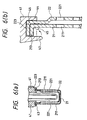
- the sleeve 416 has machined in its end, as clearly shown in Figs. 2 and 3, an annular groove 45 of a given depth to form an outer annular extension 43 and an inner annular extension 44.
- a flange 213 of the protective cover 21 is fitted in contact of an upper flat surface with the bottom 46 of the groove 45 and retained by crimping or bending the outer extension 43 inward.
- the oxygen sensing element 10 is retained in the sensor mount 41 through packing 417 and talc 416 and includes an oxygen ion conductive solid electrolyte body and a measuring and a reference electrode disposed on outer and inner surfaces of the electrolyte body.
- An inner cover 22 is, as clearly shown in Fig. 6(b), disposed inside the protective cover 21.
- the inner cover 22 has, similar to the protective cover 21, a mount flange 223 which is secured in the annular groove 45 by crimping the outer extension 43 of the sensor mount 41 together with the mount flange 213 of the protective cover 21 and a plurality of gas holes 221 formed in a side wall thereof which communicate with the gas holes 211 of the protective cover 21.
- the inner cover 22 serves as a protector which protects the oxygen sensing element 10 from impact along with the protective cover 21.
- Other arrangements are identical with those of the first embodiment, and explanation thereof in detail will be omitted here.
- Fig. 10 shows the sixth embodiment of the invention.
- the sensor mount 41 as shown in Fig. 17, has a cylindrical chamber having a diameter A of 8.2mm.
- the inner cover 22 has a bulged end portion of a diameter D of 9.9mm.
- the mount flanges 414 of the protective cover 21 and the mount flange 223 of the inner cover 22 are pressed by bending the outer extension 43 of the sensor mount 41 inward, it will cause the mount flange 414 to be deformed elastically so that the protrusions 422 and the recesses 421 move close to each other, that is, the mount flange 414 is flattened, which will produce elastic force urging the inner cover 223 and the outer extension 43 of the sensor mount 41 in opposite directions, thus resulting in an increased nip of the mount flanges 223 and 414 between the bottom 46 and the tapered wall 49 of the groove 45 and the outer extension 43.
- the positional relation between the contacts A and B may also be achieved in the eighth embodiment shown in Fig. 16.
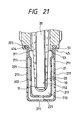
- the installation of the protective cover 21 and the inner cover 22 on the sensor mount 41 is, as shown in Fig. 21, achieved by crimping the outer extension 51 of the sensor mount 41 at a bend angle of approximately 90° to retain the mount flanges 223 and 414 within the groove 45.
- the crimping of the outer extension 51 causes the corrugated mount flange 414 of the protective cover 21 to be deformed in a thickness-wise direction thereof, thereby producing elastic pressure urging the mount flange 223 of the inner cover 22 and the outer extension 51 of the sensor mount 41 in opposite directions, thus resulting in an increased nip of the mount flanges 223 and 414 between the bottom of the groove 45 and the outer extension 51.
- Reference numerals 712 and 713 in Fig. 21 indicate a reference and a measuring chamber, respectively.
- the reference chamber 712 leads to the atmosphere through the air vents 444 and 445 as shown in Fig. 1.
- the measuring chamber 713 is filled with the gas to be measured.
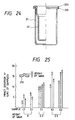
- the mount flange 414 or 223 in Fig. 23(d) is waved like bellows.
- the sample E1 has an assembly of the protective cover 21 in which the mount flange 414 has a thickness of 0.5mm and waves formed thereon whose height (distance, as shown in Fig. 25, between the top and the trough of the wave minus the thickness of the mount flange 414) is 0.2mm and the inner cover 22 in which the mount flange 223 has a thickness of 0.5mm.
- the oxygen sensor 1 of each embodiment may include the oxygen sensing element 10 formed with laminations.
- U.S.P. No. 5,573,650, issued November 12, 1996 to Fukaya et al. teaches such a structure of the oxygen sensing element 10, disclosure of which is incorporated herein by reference.
Landscapes
- Chemical & Material Sciences (AREA)
- Life Sciences & Earth Sciences (AREA)
- Health & Medical Sciences (AREA)
- Physics & Mathematics (AREA)
- Chemical Kinetics & Catalysis (AREA)
- Electrochemistry (AREA)
- Molecular Biology (AREA)
- Analytical Chemistry (AREA)
- Biochemistry (AREA)
- General Health & Medical Sciences (AREA)
- General Physics & Mathematics (AREA)
- Immunology (AREA)
- Pathology (AREA)
- Measuring Oxygen Concentration In Cells (AREA)
Abstract
Description
- The present invention relates generally to a gas sensor which may be employed in an air-fuel ratio control system for automotive vehicles for measuring the concentration of gas such O2, NOx, or CO, and more particularly to an improved structure of such a gas sensor which provides for ease of installation of a protective cover on a cover mount, firm engagement of the protective cover with the cover mount, and ease of machining of the cover mount.
- Typical gas sensors employed in measuring the concentration of O2, NOx, or CO in exhaust gasses of an internal combustion engine include a gas sensitive element, a sensor mount, and a protective cover. The sensor mount is used in mounting the sensor in an exhaust pipe and also serves as a holder which retains therein the gas sensitive element. The protective cover is installed on the sensor mount so as to cover the gas sensitive element. The gas sensors usually undergo a temperature change from room temperature to approximately 1000°C after the engine is started, thereby causing thermal stress to be produced between the sensor mount and the protective cover, which may result in dislodgment of the protective cover from the sensor mount.
- It is therefore a principal object of the present invention to avoid the disadvantages of the prior art.
- It is another object of the present invention to provide a simple structure of a gas sensor which provides for ease of installation of a protective cover on a cover mount, firm engagement of the protective cover with the cover mount, and ease of machining of the cover mount.
- According to one aspect of the invention, there is provided a gas concentration sensor. The gas concentration sensor comprises: (a) a gas concentration measuring element having a gas-exposed portion exposed to a gas to be measured; (b) a hollow cylindrical holder holding therein the gas concentration measuring element, the holder having an end surface on which an inner and an outer extension are formed to define a groove therebetween, the inner extension being is smaller in height than the outer extension; and(c) a protective cover covering the gas-exposed portion of the gas concentration measuring element, the protective cover having a flange which is retained within the groove of the holder by crimping the outer extension inward to install the protective cover on the end surface of the holder.
- In the preferred mode of the invention, a ratio of the height of the inner extension and the height of the outer extension lies within a range of 0.2 to 0.85.
- The groove in the end surface of the holder is defined by side walls of the outer and inner extensions, a bottom formed between the side walls of the outer and inner extensions, and a tapered wall extending from the bottom to the side wall of the inner extension.
- The height of the inner extension is greater than a thickness of the flange of the protective cover.
- The protective cover has a hollow body. The flange of the protective cover consists of a curved portion continuing from the hollow body and a flat portion extending from the curved portion. The flange of the protective cover is retained within the groove of the holder in elastic engagement of an end of the flat portion, the flat portion, and the curved portion with the side wall of the outer extension, the bottom, and the tapered wall, respectively.
- At least one inner protective cover is further disposed inside the protective cover. The inner protective cover has a flange retained within the groove of the holder together with the flange of the protective cover by the crimped outer extension.
- The inner protective cover may be attached directly to the flange of the protective cover.
- The protective cover and the inner protective cover have formed therein gas holes through which the gas enters inside the protective cover and the inner cover. One of the gas holes of the inner protective cover closest to the holder is closer to the holder than one of the gas holes of the protective cover closest to the holder.
- The flange of one of the protective cover and the inner protective cover may have a corrugated surface which is in contact with the flange of the other cover.
- The holder is formed with a forged member.
- The holder is made of material having a hardness lower than that of the protective cover.
- According to the second aspect of the invention, there is provided a gas concentration sensor which comprises: (a) a gas concentration measuring element having a gas-exposed portion exposed to a gas to be measured; (b) a hollow cylindrical holder holding therein the gas concentration measuring element, the holder having an end surface on which an inner and an outer extension are formed; (c) a groove formed in the end surface of the holder, the groove being defined by side walls of the outer and inner extensions, a bottom formed between the side walls of the outer and inner extensions, and a tapered wall extending from the bottom to the side wall of the inner extension; and (d) a protective cover covering the gas-exposed portion of the gas concentration measuring element, the protective cover having a flange which is retained within the groove of the holder by crimping the outer extension inward to install the protective cover on the end surface of the holder.
- In the preferred mode of the invention, the geometry of the groove of the holder is so determined that the flange of the protective cover may be fitted in the groove with a clearance of 0.4mm or less between the flange and the bottom before the outer extension is crimped.
- Specifically, the size and inclination of the tapered wall of the groove may be so determined that the flange of the protective cover may be fitted in the groove with a clearance of 0.4mm or less between the flange and the bottom before the outer extension is crimped.
- According to the third aspect of the invention, there is provided a gas concentration sensor which comprises: (a) a gas concentration measuring element having a gas-exposed portion exposed to a gas to be measured; (b) a hollow cylindrical holder holding therein the gas concentration measuring element, the holder having an end surface on which an inner and an outer extension are formed to define a groove therebetween; (c) an outer protective cover covering the gas-exposed portion of the gas concentration measuring element, the outer protective cover having a flange which is retained within the groove of the holder by crimping the outer extension inward to install the outer protective cover on the end surface of the holder; and (d) an inner protective cover disposed inside the outer protective cover, the inner protective cover having a flange which is retained within the groove of the holder in engagement with the flange of the outer protective cover by crimping the outer extension inward to install the inner protective cover on the end surface of the holder. The flange of one of the outer and inner protective cover has formed thereon protrusions which engage the flange of the other.
- In the preferred mode of the invention, a third protective cover is provided which has a flange retained within the groove of the holder in engagement with the flange of one of the outer and inner protective covers which has the protrusions.
- The protrusions are formed with undulation of a surface of the flange of the one of the outer and inner protective covers.
- The outer protective cover may have the protrusions formed on the flange thereof.
- A clearance of 0.05 to 0.2mm is developed between the inner extension and an inner wall of the inner protective cover.
- The holder is made of material having a hardness lower than that of the outer and inner protective covers.
- The groove in the end surface of the holder is defined by side walls of the outer and inner extensions, a bottom formed between the side walls of the outer and inner extensions, and a tapered wall extending from the bottom to the side wall of the inner extension. Each of the outer and inner protective covers has a hollow body. The flange of each of the outer and inner protective covers consists of a curved portion continuing from the hollow body and a flat portion extending from the curved portion. The flange of said outer protective cover engages the inner protective cover at a first contact. The curved portion of the flange of the inner protective cover engages the tapered wall of the groove at a second contact. The first contact is located outside the second contact.
- The first contact may be made at ends of the flanges of the outer and inner protective covers.
- The present invention will be understood more fully from the detailed description given hereinbelow and from the accompanying drawings of the preferred embodiments of the invention, which, however, should not be taken to limit the invention to the specific embodiments but are for the purpose of explanation and understanding only.
- In the drawings:
- Fig. 1 is a longitudinal cross sectional view which shows an oxygen sensor according to the first embodiment of the invention;
- Fig. 2 is a partially sectional view which shows a sensor mount and a protective cover;
- Fig. 3 is a partially perspective view which shows a groove formed in a sensor mount;
- Fig. 4 is an illustration which shows a relation of height between outer and inner extensions on a sensor mount;
- Fig. 5 is a perspective view which shows a protective cover
- Fig. 6(a) is a partially sectional view which shows a top of an oxygen sensor according to the second embodiment of the invention;
- Fig. 6(b) is a partially sectional view which shows a pair of protective covers retained in a sensor mount of the oxygen sensor shown in Fig. 6(a);
- Fig. 7 is a partially sectional view which shows a pair of protective covers retained in a sensor mount according to the third embodiment of the invention;
- Fig. 8 is a partially sectional view which shows a pair of protective covers retained in a sensor mount according to the fourth embodiment of the invention;
- Fig. 9 is a partially sectional view which shows three protective covers retained in a sensor mount according to the third embodiment of the invention;
- Fig. 10 is a perspective view which shows a protective cover according to the sixth embodiment of the invention;
- Fig. 11 is a cross sectional view which shows a pair of protective covers according to the seventh embodiment of the invention;
- Fig. 12(a) is a graph which shows a variation in output of an oxygen sensor;
- Fig. 12(b) is a graph which shows amplitudes of outputs of an oxygen sensor in which line C1, as shown in Fig. 11, is closer to a sensor mount than line C2 and an oxygen sensor in which line C2 is closer to the sensor mount than line C1;
- Fig. 13 is a longitudinal cross sectional view which shows an oxygen sensor according to the eighth embodiment of the invention;
- Fig. 14 is a partially sectional view which shows an annular groove formed in a sensor mount of the eighth embodiment;
- Fig. 15 is a partially sectional view which shows a pair of protective covers fitted within a groove before an outer extension on a sensor mount is crimped;
- Fig. 16 is a partially sectional view which shows the protective covers in the groove, as illustrated in Fig. 15, after the outer extension on the sensor mount is crimped;
- Fig. 17 is an illustration which shows the protective covers, as illustrated in Fig. 15, before installed on the sensor mount;
- Fig. 18 is a perspective view which shows a pair of protective covers according to the ninth embodiment of the invention;
- Fig. 19 is a partially sectional view which shows installation of flanges of the protective covers, as illustrated in Fig. 18, within a groove of a sensor mount;
- Fig. 20(a) is a partially sectional view which shows a sensor mount according to the tenth embodiment of the invention;
- Fig. 20(b) is a partially sectional view which shows a pair of protective covers according to the tenth embodiment of the invention;
- Fig. 21 is a partially sectional view which shows the protective covers, as illustrated in Fig. 20(b), installed on a sensor mount;
- Fig. 22 is a partially sectional view which shows three protective covers installed on a sensor mount according the eleventh embodiment of the invention;
- Figs. 23(a), 23(b), 23(c), 23(d), 23(e), and 23(f) are partially sectional views which show a variety of examples of corrugation of a flange of a protective cover;
- Fig. 24 is a partially sectional view which shows a comparative sample of a combination of an inner cover and a protective cover with a flat mount flange for endurance tests;
- Fig. 25 is a graph which shows results of endurance tests performed for different heights of waves formed on a flange of a protective cover; and
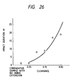
- Fig. 26 is a graph which shows results of endurance tests performed for different clearances between an outer side wall of an inner extension on a sensor mount and an inner wall of an inner cover.
-
- Referring now to the drawings, wherein like numbers refer to like parts in several views, particularly to Fig. 1, there is shown an
oxygen sensor 1 according to the first embodiment of the invention which is employed in automotive air-fuel ratio control systems to measure an oxygen content in exhaust gasses of an internal combustion engine. Note that the present invention is not limited to the oxygen sensor and may alternatively be used with any other gas sensors such as HC, CO, and NOx sensors. - The
oxygen sensor 1 generally includes anoxygen sensing element 10, a hollowcylindrical housing 40, and a cylindricalprotective cover 21. Theoxygen sensing element 10 has formed on its end a gas-exposedportion 11 exposed to the gas to be measured. Thehousing 40 has asensor mount 41. Thesensor mount 41 is, as described later in detail, used for installation of theoxygen sensor 1 and also serves as a holder which holds therein the gas-exposedportion 11 of theoxygen sensing element 10. Theprotective cover 21 covers the gas-exposedportion 11 of theoxygen sensing element 10 and has formed therein a plurality ofgas holes 211 through which the gas flows inside theprotective cover 11. - The
sensor mount 41 is made of a hollow cylindrical member consisting of amount flange 415 and asleeve 416. Thesleeve 416 has machined in its end, as clearly shown in Figs. 2 and 3, anannular groove 45 of a given depth to form an outerannular extension 43 and an innerannular extension 44. Within thegroove 45, aflange 213 of theprotective cover 21 is fitted in contact of an upper flat surface with the bottom 46 of thegroove 45 and retained by crimping or bending theouter extension 43 inward. - The height U of the
inner extension 44 of thesensor mount 41, as shown in Fig. 2, is smaller than the height K of theouter extension 43. The height K of theouter extension 43 is greater than the thickness of theflange 213 of theprotective cover 21. In this embodiment, the height U of theinner extension 44 is 1.4mm. The height K of theouter extension 43 is 2.4mm. It is advisable that the heights U and K be determined so that the ratio U/K may lie within a range of 0.2 to 0.85, preferably 0.35 to 0.75 for machinability of thegroove 45 and theprotective cover 21 and retentivity of theprotective cover 21 within thegroove 45. - The
protective cover 21, as clearly shown in Fig. 5, has ahollow cylinder 210 and theflange 213 formed on an open end of thecylinder 210. Thecylinder 210 has formed therein the gas holes 211 through which the gas to be measured flows. - The
sensor mount 41 is made of the stainless steel SUS430 having a hardness Hv of approximately 220. Theprotective cover 21 is made of the stainless steel SUS310CP having a hardness Hv of approximately 350. Thesensor mount 41 is, thus, softer than theprotective cover 21 so that theflange 213 of theprotective cover 21 can bite into theannular groove 45 of thesensor mount 41 by crimping theouter extension 43 firmly, thus allowing theprotective cover 21 to be retained on thesensor mount 41 without any play in a circumferential direction. Further, the crimping of theouter extension 43 causes the sensor mount 41 (i.e., the groove 45) to be pressed elastically, which will produce reactive force to increase an elastic nip of theflange 213 in a lengthwise direction of theprotective cover 21. - The
inner extension 44 of thesensor mount 41 has a minimum height (i.e., the height U) enough to support an inner wall of the end of theprotective cover 21 which is, as described above, smaller than that of theouter extension 43 used in retaining theprotective cover 21, thereby minimizing the length of a cylindrical space defined between an inner wall of thecylinder 416 of thesensor mount 41 and an outer wall of theoxygen sensing element 10. This suppresses reaction of carbon sticking to theoxygen sensing element 10 with platinum of electrodes provided in theoxygen sensing element 10 and prevents the carbon from growing, thus avoiding the deterioration of the electrodes caused by a deposit of the carbon and peeling of a coating from theoxygen sensing element 10, which assures an increased service life of the oxygen sensor. - The formation of the
annular groove 45 is, as shown in Fig. 4, accomplished by first preparing a forged housing block having a stepped orshoulder portion 450 formed on an end thereof and machining theshoulder portion 450 to a depth corresponding to the height U of theinner extension 44. This results in a decrease in machining load by an amount corresponding to the difference in height between the outer andinner extensions 43 and 44 (i.e., K - U) as compared with a conventional structure wherein outer and inner extensions have the same height. The decrease in machining load is also promoted by integral formation of theouter extension 43 on the housing block. - The decreased height U of the
inner extension 44 also facilitates ease of fitting of theflange 213 of theprotective cover 21 into theannular groove 45, thus resulting in ease of installation of theprotective cover 21 on thesensor mount 41. - The
oxygen sensor 1 of this embodiment is, as described above, designed as an air-fuel ratio sensor measuring the air-fuel ratio in an internal combustion engine for automotive vehicles. - The installation of the
oxygen sensor 1 in the vehicle is accomplished by screwingthreads 414 formed an outer wall of thesensor mount 41 to a threaded hole in an exhaust pipe of the engine. Themount flange 415 is in contact with the outer wall of the exhaust pipe through agasket 462. - The
oxygen sensor 1 also includes outer andinner covers end cover 443, and a water-repellent filter 446. Theinner cover 442b is joined at an end to an upper end of thehousing 40 through ametallic ring 463. Theouter cover 442a is joined to an upper portion of theinner cover 442b by crimping. Theend cover 443 covers the upper end of theouter cover 442a. Theend cover 443 and theouter cover 442a haveair vents repellent filter 446 for introducing through an air passage (not shown) the reference gas, e.g., the air into a chamber within which theoxygen sensing element 10 is disposed. - The
oxygen sensing element 10 is retained in thesensor mount 41 through packing 417 andtalc 416 and includes an oxygen ion conductive solid electrolyte body and a measuring and a reference electrode disposed on outer and inner surfaces of the electrolyte body. - A bar-shaped
heater unit 20 is retained within theoxygen sensing element 10 through aholder 47. Theheater unit 20 includes a heating conductor which connects with afeeder 333 and which heats the measuring and reference electrodes of theoxygen sensing element 10 up to a temperature at which the oxygen concentration is allowed to be measured correctly. -
Leads 161 and thefeeder 333 are retained within thecovers rubber bush 447. The leads 161 connect with the electrodes of theoxygen sensing element 10 throughconnectors signal pickup lines connectors glass block 13 mounted in thecovers - For a more detailed structure and operation of the
oxygen sensor 1, reference is made to U.S.Appln. No. 09/196,693, filed on November 20, 1998, assigned to the same assignee as that of this application, disclosure of which is incorporated herein by reference. - Figs. 6(a) and 6(b) show the second embodiment of the invention.
- An
inner cover 22 is, as clearly shown in Fig. 6(b), disposed inside theprotective cover 21. Theinner cover 22 has, similar to theprotective cover 21, amount flange 223 which is secured in theannular groove 45 by crimping theouter extension 43 of thesensor mount 41 together with themount flange 213 of theprotective cover 21 and a plurality ofgas holes 221 formed in a side wall thereof which communicate with the gas holes 211 of theprotective cover 21. Theinner cover 22 serves as a protector which protects theoxygen sensing element 10 from impact along with theprotective cover 21. Other arrangements are identical with those of the first embodiment, and explanation thereof in detail will be omitted here. - Fig. 7 shows the third embodiment of the invention which has an
inner cover 22a serving as a protector, like theinner cover 22 of the second embodiment. Theinner cover 22a has a bulgedend portion 27 which is attached to an inner wall of theprotective cover 21 at a weldedportion 28. The location of the weldedportion 28 is not limited to the illustrated one and may be on a corner of the bottom of theinner cover 22a. Themount flange 213 of theprotective cover 21 is, similar to the first embodiment, retained by theouter extension 43 of thesensor mount 41. Other arrangements are identical with those of the first embodiment, and explanation thereof in detail will be omitted here. - Fig. 8 shows the fourth embodiment of the invention which is a modification of the second embodiment in Figs. 6(a) and 6(b).
- The
inner cover 22 has a funnel-shapedportion 225 connecting themount flange 223 and thecylindrical body 220 of theinner cover 22. The funnel-shapedportion 225 is closer to theinner extension 44 of thesensor mount 41 than the second embodiment, thereby increasing an outer area of thecylindrical body 220, thus resulting in an increase in freedom in designing the gas holes 221. - Fig. 9 shows the fifth embodiment of the invention which is a modification of the fourth embodiment and which has an intermediate
protective cover 23 disposed between theprotective cover 21 and theinner cover 22. The intermediateprotective cover 23 has amount flange 233 which is retained within thegroove 45 of thesensor mount 41 together with themount flanges protective cover 21 and theinner cover 22. The intermediateprotective cover 23 hasgas holes 231 formed in a cylindrical body thereof which establish fluid communication between the gas holes 211 and 221. Other arrangements are identical with those of the fourth embodiment, and explanation thereof in detail will be omitted here. - Fig. 10 shows the sixth embodiment of the invention.
- The
protective cover 21 of this embodiment has themount flange 214 with a corrugated periphery. Themount flange 213 is also waved in a thickness-wise direction thereof so that it may be elastically deformed when pressed against the bottom 46 of thegroove 45 by crimping theouter extension 43 of thesensor mount 41, thereby increasing an elastic nip of theflange 214 between the bottom of thegroove 45 and theouter extension 43 in lengthwise and circumferential directions of theprotective cover 21. Other arrangements are identical with those of the first embodiment, and explanation thereof in detail will be omitted here. Themount flange 223 of theinner cover 22 may also be corrugated like themount flange 214 of theprotective cover 21. - Fig. 11 shows the seventh embodiment of the invention which has, similar to the second embodiment, the
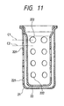
inner cover 22. - The
protective cover 21 and theinner cover 22 havegas holes inner cover 22 closest to thesensor mount 41 lies on a line C1 which is shifted at a given interval away from a line C2 on which one of horizontal arrays of the gas holes 221 of theprotective cover 21 closest to thesensor mount 41 lies so that the gas holes 222 may be out of alignment with the gas holes 221, thereby causing the gas to flow from the gas holes 221 to the gas holes 222, and vice versa, through the whole of a chamber defined between theprotective cover 21 and theinner cover 22, thus enhancing an exchange of gasses to be measured. - The
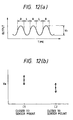
oxygen sensor 1 installed in the exhaust pipe of the engine outputs a signal, as shown in Fig. 12(a), which changes in level cyclically with a change in air-fuel ratio of a mixture. Portions of the signal, as labeled "R" indicate rich air-fuel ratios, while portions, as labeled "L" indicate lean air-fuel ratios. The inventors of this application prepared two oxygen sensors one of which has the line C1 of theinner cover 22, as shown in Fig. 11, located closer to thesensor mount 41 than the line C2 and the other of which has the line C2 of theprotective cover 21 located closer to thesensor mount 41 than the line C1 and measured amplitudes Va of outputs of the two oxygen sensors. The results are shown in Fig. 12(b). It is found that the oxygen sensor in which the line C1 of theinner cover 22 is located closer to thesensor mount 41 than the line C2 has a greater amplitude Va, thus increasing the efficiency of an exchange of exhaust gasses to be measured. - Figs. 13 to 17 show the
oxygen sensor 1 according to the eighth embodiment of the invention. - The
protective cover 21 and theinner cover 22 are installed at themount flanges annular groove 45 of thesensor mount 41. Themount flanges mount flange 223 has a radius of curvature of 1.1mm at aninside corner 118. - The
sensor mount 41, as shown in Fig. 17, has a cylindrical chamber having a diameter A of 8.2mm. Theinner cover 22 has a bulged end portion of a diameter D of 9.9mm. - The
annular groove 45 is, as clearly shown in Fig. 14, defined by aninner side wall 440 of theinner extension 44, aninner side wall 430 of theouter extension 43, an annular flat bottom 46, and a slope or taperedwall 49. The taperedwall 49 connects the bottom 46 and theinner side wall 440 and is oriented at an angle C of 45° relative to the innercylindrical wall 300 of thesensor mount 41. The height B of the taperedwall 49 is 0.9mm. The inclination (i.e., the angle C) and height B of the taperedwall 49 may be determined within ranges that create, as shown in Fig. 15, a clearance F of 0.4mm or less, preferably 0.05 to 0.3mm between themount flange 223 of theinner cover 22 and the bottom 46. - The
sensor mount 41, as shown in Fig. 17, has a cylindrical chamber having a diameter A of 8.2mm and is made of SUS430. Theprotective cover 21 and theinner cover 22 are made of SUS310S. - The installation of the
protective cover 21 and theinner cover 22 on thesensor mount 41 is accomplished in the following manner. - First, the
protective cover 21 and theinner cover 22 are welded together, as indicated at 119 in Fig. 18, just below themount flanges mount flanges groove 45 in engagement of thecorner 118 of theinner cover 22 and ends 115 and 116 of themount flanges wall 49 and theinner side wall 430, respectively. The clearance F between themount flange 223 of theinner cover 22 and the bottom 46 is 0.15mm. The ends 115 and 116 of themount flanges inner side wall 430. - Finally, the
outer extension 43 is bent inward, as shown in Fig. 16, to press themount flanges wall 49, thereby causing themount flanges mount flanges groove 45 at three points X, Y, and Z in cross section (i.e., outer edges of themount flanges - The
protective cover 21 and theinner cover 22 may alternatively be installed in thesensor mount 41 by crimping without being welded at numeral 119 in Fig. 17. - The
protective cover 21 and theinner cover 22 are, as described above, made of the stainless steel different from that of thesensor mount 41, so that a difference in coefficient of thermal expansion therebetween will be approximately 7 × 10⁻⁶ at 800°C. Theoxygen sensor 1 is, as described above, installed in the exhaust pipe of the engine and thus undergoes a temperature change from room temperature to approximately 1000°C after the engine is started. This will cause thermal stress to be produced between thesensor mount 41 and thecovers mount flanges mount flanges groove 45. - Figs. 18 and 19 show the ninth embodiment of the invention which is different from the eighth embodiment only in structure of the
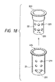
protective cover 21. Other arrangements are identical, and explanation thereof in detail will be omitted here. - The
protective cover 21 has amount flange 414 corrugated in a width-wise direction. Specifically, themount flange 414 is waved to form, as shown in Fig. 19, protrusions 422 (i.e., tops of waves) and recesses 421 (i.e., troughs of the waves). Thus, when themount flanges 414 of theprotective cover 21 and themount flange 223 of theinner cover 22 are pressed by bending theouter extension 43 of thesensor mount 41 inward, it will cause themount flange 414 to be deformed elastically so that theprotrusions 422 and therecesses 421 move close to each other, that is, themount flange 414 is flattened, which will produce elastic force urging theinner cover 223 and theouter extension 43 of thesensor mount 41 in opposite directions, thus resulting in an increased nip of themount flanges wall 49 of thegroove 45 and theouter extension 43. - It is advisable that the
mount flanges groove 45 so that a contact A of themount flanges mount flange 223 and the taperedwall 49. This positional relation causes the pressure produced by crimping theouter extension 43 of thesensor mount 41 exerted on theprotective cover 21 and theinner cover 22 to be transformed into rotation moment or torque oriented around the contact B clockwise, as viewed in the drawing, thereby allowing a nip of ends of themount flanges groove 45 and theouter extension 43 to be increased. - The contact A of the
mount flanges - The positional relation between the contacts A and B may also be achieved in the eighth embodiment shown in Fig. 16.
- Figs. 20(a), 20(b), and 21 show the tenth embodiment of the invention which is a modification of the ninth embodiment in Figs. 18 and 19.
- The
sensor mount 41, as clearly shown in Fig. 20(a), has formed in its end anannular groove 45 to form outer and innerannular extensions - The
protective cover 21 and theinner cover 22 are identical in structure with the ones shown in Figs. 18. Specifically, theinner cover 22, as clearly shown in Fig. 21, consists of a bulgedportion 311 and asleeve portion 312 with a bottom and has two horizontal arrays of eightgas holes 221 formed in thesleeve portion 312 and onegas hole 221 formed in the bottom (the total number of the gas holes 221 is seventeen). The bulgedportion 311 has formed at an end thereof themount flange 223 which has a flat surface contact with the bottom of thegroove 45. Theprotective cover 21 has three horizontal arrays of eightgas holes 211 formed in a side wall and onegas hole 211 formed in a bottom (the total number of the gas holes 211 is twenty four). Theprotective cover 21 also has the corrugatedflange 414 identical with the one shown in Fig. 18. Instead of theprotective cover 21, theinner cover 22 may have the corrugatedflange 414. - The installation of the
protective cover 21 and theinner cover 22 on thesensor mount 41 is, as shown in Fig. 21, achieved by crimping theouter extension 51 of thesensor mount 41 at a bend angle of approximately 90° to retain themount flanges groove 45. The crimping of theouter extension 51 causes thecorrugated mount flange 414 of theprotective cover 21 to be deformed in a thickness-wise direction thereof, thereby producing elastic pressure urging themount flange 223 of theinner cover 22 and theouter extension 51 of thesensor mount 41 in opposite directions, thus resulting in an increased nip of themount flanges groove 45 and theouter extension 51. -
Reference numerals reference chamber 712 leads to the atmosphere through theair vents chamber 713 is filled with the gas to be measured. - Fig. 22 shows the eleventh embodiment of the invention which is different from the tenth embodiment in Figs. 20(a), 20(b), and 21 in that a second
inner cover 63 having aflat mount flange 619 is disposed inside theinner cover 22 and in that themount flange 223 of theinner cover 22 is corrugated in a thickness-wise direction, while themount flange 414 of theprotective cover 21 is flattened. Other arrangements are identical, and explanation thereof in detail will be omitted here. - Figs. 23(a) to 23(f) show examples of corrugation of the
mount flange 414 of theprotective cover 21 in the tenth embodiment or themount flange 223 of theinner cover 22 in the eleventh embodiment. - The waves of the
mount flange troughs 421. - The waves of the
mount flange troughs 421. - The waves of the
mount flange - The
mount flange - The
mount flange waves 493 of U-shape in cross section formed thereon at regular intervals. - The
mount flange waves 493 of U-shape in cross section formed on an upper and a lower surface thereof alternately. - The inventors of this application performed endurance tests applying 90G six samples E1 to E4, C1, and C2 of the
oxygen sensor 1 using an impact tester. - The sample E1 has an assembly of the
protective cover 21 in which themount flange 414 has a thickness of 0.5mm and waves formed thereon whose height (distance, as shown in Fig. 25, between the top and the trough of the wave minus the thickness of the mount flange 414) is 0.2mm and theinner cover 22 in which themount flange 223 has a thickness of 0.5mm. - The sample E2 is identical with the sample E1 except that the height of the waves formed on the
mount flange 414 is 0.5mm. - The sample E3 is identical with the sample E2 except that the
mount flanges - The sample C1 is identical with the sample E1 except that the
protective cover 21 has, as shown in Fig. 24, theflat mount flange 213. - The sample C2 is identical with the sample C1 except that the
mount flanges - The results of the tests are illustrated in a graph of Fig. 25. " ○ " indicates the length of time each sample withstood the impact without any looseness of the assembly of the
protective cover 21 and theinner cover 22 within thegroove 45 of thesensor mount 41. "▵" indicates the time when unwanted play occurred between the assembly of thecovers groove 45. "X" indicates the time when the assembly of thecovers groove 45. Each sample were tested two to four times. - The graph shows that the samples E1 to E2 in which the
mount flange 414 of theprotective cover 21 are undulated all have the durability higher than that of the samples C1 and C2 and the durability increases as the thickness of each of themount flanges mount flange 414 is 0.2mm has a variation in durability. It is, thus, found that theoxygen sensor 1 has the stable durability when the height of the waves of themount flange 414 of theprotective cover 22 is more than 0.2mm. - The inventor of this application also tested six samples of the
oxygen sensor 1 in the tenth embodiment for durability for different clearances between an outer side wall of theinner extension 53 of thesensor mount 41 and an inner wall of theinner cover 22. Note that the clearance between the outer side wall of theinner extension 53 and the inner wall of theinner cover 22 is defined by one-half of a difference between inner diameter of theinner cover 22 and outer diameter of theinner extension 53. - Five of the six samples have different clearances of 0.05 to 0.25mm. The other is a comparative sample in which the
sensor mount 1 does not have theinner extension 53. 90G heating impact tests were performed by applying an impact force of 90G to the samples 800 to 1000 times per minute at ambient temperatures of 800 to 900°C. The results of the tests are shown in a graph of Fig. 26. "▵" indicates the time when unwanted play occurred between the assembly of thecovers groove 45. - The graph shows that the sample in which the clearance between the outer side wall of the
inner extension 53 of thesensor mount 41 and the inner wall of theinner cover 22 is 0.25mm has substantially the same durability of that of the comparative sample and that the durability increases as the clearance decreases. Usually, it is difficult to decrease the clearance below 0.05mm for installation of the assembly of thecovers groove 45. It is, thus, advisable that the clearance between the outer side wall of theinner extension 53 of thesensor mount 41 and the inner wall of theinner cover 22 be in a range of 0.05 to 0.20mm. - While the present invention has been disclosed in terms of the preferred embodiments in order to facilitate better understanding thereof, it should be appreciated that the invention can be embodied in various ways without departing from the principle of the invention. Therefore, the invention should be understood to include all possible embodiments and modifications to the shown embodiments which can be embodied without departing from the principle of the invention as set forth in the appended claims.
- The
oxygen sensor 1 of each embodiment may include theoxygen sensing element 10 formed with laminations. For example, U.S.P. No. 5,573,650, issued November 12, 1996 to Fukaya et al., teaches such a structure of theoxygen sensing element 10, disclosure of which is incorporated herein by reference. - The gas holes 221, 221, and 222 may alternatively be formed with slits.
- While the
sensor mount 41 is made of the stainless steel SUS430 having a hardness Hv of approximately 220, and theprotective cover 21 is made of the stainless steel SUS310CP having a hardness Hv of approximately 350, themount flanges sensor mount 41 for increasing bite of theflanges groove 45 of thesensor mount 41. - An improved structure of a gas sensor is provided. The gas sensor includes a gas sensitive element, a holder retaining therein the gas sensitive element, and a protective cover installed on the holder. The protective cover has a flange which is retained in a groove formed in the holder by crimping an outer extension formed on the holder adjacent the groove. The geometries of the groove in the holder and the flange of the protective cover are so determined as to provide for ease of installation of the protective cover on the holder, firm engagement of the protective cover with the groove of the holder, and ease of machining of the groove of the holder.
Claims (24)
- A gas concentration sensor comprising:a gas concentration measuring element having a gas-exposed portion exposed to a gas to be measured;a hollow cylindrical holder holding therein said gas concentration measuring element, said holder having an end surface on which an inner and an outer extension are formed to define a groove therebetween, the inner extension being is smaller in height than the outer extension; anda protective cover covering the gas-exposed portion of said gas concentration measuring element, said protective cover having a flange which is retained within the groove of said holder by crimping the outer extension inward to install said protective cover on the end surface of said holder.
- A gas concentration sensor as set forth in claim 1, wherein a ratio of the height of the inner extension and the height of the outer extension lies within a range of 0.2 to 0.85.
- A gas concentration sensor as set forth in claim 1, wherein the groove in the end surface of said holder is defined by side walls of the outer and inner extensions, a bottom formed between the side walls of the outer and inner extensions, and a tapered wall extending from the bottom to the side wall of the inner extension.
- A gas concentration sensor as set forth in claim 1, wherein the height of the inner extension is greater than a thickness of the flange of said protective cover.
- A gas concentration sensor as set forth in claim 3, wherein said protective cover has a hollow body, the flange of said protective cover consisting of a curved portion continuing from the hollow body and a flat portion extending from the curved portion, and wherein the flange of said protective cover is retained within the groove of said holder in elastic engagement of an end of the flat portion, the flat portion, and the curved portion with the side wall of the outer extension, the bottom, and the tapered wall, respectively.
- A gas concentration sensor as set forth in claim 1, further comprising at least one inner protective cover disposed inside said protective cover, said inner protective cover having a flange retained within the groove of said holder together with the flange of said protective cover by the crimped outer extension.
- A gas concentration sensor as set forth in claim 6, wherein said inner protective cover has a hollow body, the flange of said protective cover consisting of a curved portion continuing from the hollow body and a flat portion extending from the curved portion, and wherein the flange of said inner cover is retained within the groove of said holder in elastic engagement of an end of the flat portion and the curved portion with the side wall of the outer extension and the tapered wall, respectively.
- A gas concentration sensor as set forth in claim 1, further comprising an inner protective cover disposed inside said protective cover, said inner protective cover being attached to the flange of said protective cover.
- A gas concentration sensor as set forth in claim 7, wherein said protective cover and said inner protective cover have formed therein gas holes through which the gas enters inside said protective cover and said inner cover, one of the gas holes of said inner protective cover closest to said holder being closer to said holder than one of the gas holes of said protective cover closest to said holder.
- A gas concentration sensor as set forth in claim 7, wherein the flange of one of said protective cover and said inner protective cover has a corrugated surface which is in contact with the flange of the other cover.
- A gas concentration sensor as set forth in claim 1, wherein said holder is made of a forged member.
- A gas concentration sensor as set forth in claim 1, wherein said holder is made of material having a hardness lower than that of said protective cover.
- A gas concentration sensor comprising:a gas concentration measuring element having a gas-exposed portion exposed to a gas to be measured;a hollow cylindrical holder holding therein said gas concentration measuring element, said holder having an end surface on which an inner and an outer extension are formed;a groove formed in the end surface of said holder, said groove being defined by side walls of the outer and inner extensions, a bottom formed between the side walls of the outer and inner extensions, and a tapered wall extending from the bottom to the side wall of the inner extension; anda protective cover covering the gas-exposed portion of said gas concentration measuring element, said protective cover having a flange which is retained within the groove of said holder by crimping the outer extension inward to install said protective cover on the end surface of said holder.
- A gas concentration sensor as set forth in claim 13, wherein the geometry of said groove of said holder is so determined that the flange of said protective cover may be fitted in the groove with a clearance of 0.4mm or less between the flange and the bottom before crimping the outer extension.
- A gas concentration sensor as set forth in claim 13, wherein the size and inclination of the tapered wall of said groove are so determined that the flange of said protective cover may be fitted in the groove with a clearance of 0.4mm or less between the flange and the bottom before crimping the outer extension.
- A gas concentration sensor comprising:a gas concentration measuring element having a gas-exposed portion exposed to a gas to be measured;a hollow cylindrical holder holding therein said gas concentration measuring element, said holder having an end surface on which an inner and an outer extension are formed to define a groove therebetween;an outer protective cover covering the gas-exposed portion of said gas concentration measuring element, said outer protective cover having a flange which is retained within the groove of said holder by crimping the outer extension inward to install said outer protective cover on the end surface of said holder; andan inner protective cover disposed inside said outer protective cover, said inner protective cover having a flange which is retained within the groove of said holder in engagement with the flange of said outer protective cover by crimping the outer extension inward to install said inner protective cover on the end surface of said holder,
wherein the flange of one of said outer and inner protective cover has formed thereon protrusions which engage the flange of the other. - A gas concentration sensor as set forth in claim 16, further comprising a third protective cover having a flange retained within the groove of said holder in engagement with the flange of one of said outer and inner protective covers which has the protrusions.
- A gas concentration sensor as set forth in claim 16, wherein the protrusions are formed with undulation of a surface of the flange of the one of said outer and inner protective covers.
- A gas concentration sensor as set forth in claim 16, wherein said outer protective cover has the protrusions formed on the flange thereof.
- A gas concentration sensor as set forth in claim 16, wherein the inner extension of said holder has an inner annular wall facing an inner wall of said inner protective cover.
- A gas concentration sensor as set forth in claim 16, wherein a clearance of 0.05 to 0.2mm is developed between the inner extension and an inner wall of said inner protective cover.
- A gas concentration sensor as set forth in claim 16, wherein said holder is made of material having a hardness lower than that of said outer and inner protective covers.
- A gas concentration sensor as set forth in claim 16, wherein the groove in the end surface of said holder is defined by side walls of the outer and inner extensions, a bottom formed between the side walls of the outer and inner extensions, and a tapered wall extending from the bottom to the side wall of the inner extension, and wherein each of said outer and inner protective covers has a hollow body, the flange of each of said outer and inner protective covers consisting of a curved portion continuing from the hollow body and a flat portion extending from the curved portion, the flange of said outer protective cover engaging said inner protective cover at a first contact, the curved portion of the flange of said inner protective cover engaging the tapered wall of the groove at a second contact, the first contact being located outside the second contact.
- A gas concentration sensor as set forth in claim 23, wherein the first contact is made at ends of the flanges of the outer and inner protective covers.
Applications Claiming Priority (8)
| Application Number | Priority Date | Filing Date | Title |
|---|---|---|---|
| JP19743098 | 1998-07-13 | ||
| JP19743098 | 1998-07-13 | ||
| JP35919498 | 1998-12-17 | ||
| JP35919498A JP3867423B2 (en) | 1998-12-17 | 1998-12-17 | Gas sensor |
| JP36940198 | 1998-12-25 | ||
| JP36940198A JP3820785B2 (en) | 1998-07-13 | 1998-12-25 | Gas sensor |
| JP36939898 | 1998-12-25 | ||
| JP36939898 | 1998-12-25 |
Publications (3)
| Publication Number | Publication Date |
|---|---|
| EP0974836A2 true EP0974836A2 (en) | 2000-01-26 |
| EP0974836A3 EP0974836A3 (en) | 2004-12-22 |
| EP0974836B1 EP0974836B1 (en) | 2014-01-15 |
Family
ID=27475867
Family Applications (1)
| Application Number | Title | Priority Date | Filing Date |
|---|---|---|---|
| EP99113426.3A Expired - Lifetime EP0974836B1 (en) | 1998-07-13 | 1999-07-12 | Gas sensor having improved structure for installation of protective cover |
Country Status (2)
| Country | Link |
|---|---|
| US (1) | US6214186B1 (en) |
| EP (1) | EP0974836B1 (en) |
Cited By (10)
| Publication number | Priority date | Publication date | Assignee | Title |
|---|---|---|---|---|
| EP1139098A2 (en) * | 2000-03-27 | 2001-10-04 | Denso Corporation | Gas sensor having a structure for the installation of a protective cover |
| EP1391724A1 (en) * | 2002-08-20 | 2004-02-25 | Ngk Spark Plug Co., Ltd. | Gas sensor with protective cover and manufacturing method thereof |
| FR2849198A1 (en) * | 2002-12-20 | 2004-06-25 | Denso Corp | Detector construction, for vehicle exhaust gases, has cylindrical casing with porcelain insulators, detection element and end caps |
| EP1471346A1 (en) | 2003-03-31 | 2004-10-27 | Ngk Insulators, Ltd. | Gas sensor |
| WO2006005641A1 (en) * | 2004-07-14 | 2006-01-19 | Robert Bosch Gmbh | Sensor comprising a triple protection tube |
| WO2008074545A1 (en) * | 2006-12-20 | 2008-06-26 | Robert Bosch Gmbh | Gas sensor |
| DE102004038361B4 (en) * | 2003-08-08 | 2012-10-11 | Denso Corporation | Manufacturing process for gas sensor |
| CN103196953A (en) * | 2013-03-20 | 2013-07-10 | 无锡隆盛科技股份有限公司 | Packaging structure of flat plate type oxygen sensor |
| EP1818665A3 (en) * | 2006-02-10 | 2014-06-18 | Robert Bosch Gmbh | Particle sensor |
| CN104792846B (en) * | 2014-12-10 | 2017-10-03 | 中国第一汽车股份有限公司 | Available for NOXThe Multi-function protective cover and its coating production of sensor |
Families Citing this family (13)
| Publication number | Priority date | Publication date | Assignee | Title |
|---|---|---|---|---|
| JP3703627B2 (en) * | 1998-06-18 | 2005-10-05 | 日本特殊陶業株式会社 | Gas sensor |
| JP3531859B2 (en) * | 1998-09-28 | 2004-05-31 | 株式会社デンソー | Gas sensor |
| JP2003107033A (en) * | 2001-07-27 | 2003-04-09 | Denso Corp | Gas sensor |
| DE102004062189B4 (en) * | 2003-12-24 | 2018-10-11 | Denso Corporation | Structure of a gas sensor for reducing mechanical damage of the sensor element |
| JP2006064425A (en) * | 2004-08-25 | 2006-03-09 | Yamaha Marine Co Ltd | Exhaust gas sensor |
| JP4387277B2 (en) * | 2004-09-28 | 2009-12-16 | 日本特殊陶業株式会社 | Gas sensor |
| JP2009002846A (en) * | 2007-06-22 | 2009-01-08 | Denso Corp | Gas sensor and its manufacturing method |
| ES2541081B2 (en) * | 2015-04-07 | 2016-01-05 | Francisco Albero S.A.U. | Diesel combustion gas sensor |
| JP6466802B2 (en) * | 2015-08-25 | 2019-02-06 | 日本碍子株式会社 | Gas sensor and gas sensor manufacturing method |
| JP6617528B2 (en) * | 2015-11-17 | 2019-12-11 | 株式会社デンソー | Gas sensor |
| JP6740921B2 (en) | 2017-02-02 | 2020-08-19 | 株式会社デンソー | Gas sensor |
| JP6740922B2 (en) * | 2017-02-02 | 2020-08-19 | 株式会社デンソー | Gas sensor |
| US10969372B2 (en) * | 2017-12-11 | 2021-04-06 | Ngk Spark Plug Co., Ltd. | Gas sensor |
Citations (3)
| Publication number | Priority date | Publication date | Assignee | Title |
|---|---|---|---|---|
| US4756885A (en) | 1984-07-06 | 1988-07-12 | Robert Bosch Gmbh | Measuring sensor for determining the oxygen content in gases |
| US5573650A (en) | 1993-01-28 | 1996-11-12 | Nippondenso Co., Ltd. | Gas sensor |
| US5762771A (en) | 1996-02-06 | 1998-06-09 | Denso Corporation | Air-fuel ratio sensor |
Family Cites Families (6)
| Publication number | Priority date | Publication date | Assignee | Title |
|---|---|---|---|---|
| US4159234A (en) * | 1978-02-21 | 1979-06-26 | Bendix Autolite Corporation | Oxygen sensor |
| JP2670718B2 (en) | 1991-07-11 | 1997-10-29 | 株式会社キッツ | Irrigation and liquid fertilizer mixing unit |
| JPH05249069A (en) * | 1992-03-09 | 1993-09-28 | Atsugi Unisia Corp | Xoygen sensor |
| JPH0747490B2 (en) | 1992-07-13 | 1995-05-24 | 科学技術庁無機材質研究所長 | Bi5O7 (NO3) manufacturing method |
| DE4318789A1 (en) * | 1993-06-05 | 1994-12-08 | Bosch Gmbh Robert | Seal for a sensor element of a gas sensor |
| JP3624498B2 (en) * | 1995-10-27 | 2005-03-02 | 株式会社デンソー | Air-fuel ratio sensor |
-
1999
- 1999-07-12 US US09/350,676 patent/US6214186B1/en not_active Expired - Lifetime
- 1999-07-12 EP EP99113426.3A patent/EP0974836B1/en not_active Expired - Lifetime
Patent Citations (3)
| Publication number | Priority date | Publication date | Assignee | Title |
|---|---|---|---|---|
| US4756885A (en) | 1984-07-06 | 1988-07-12 | Robert Bosch Gmbh | Measuring sensor for determining the oxygen content in gases |
| US5573650A (en) | 1993-01-28 | 1996-11-12 | Nippondenso Co., Ltd. | Gas sensor |
| US5762771A (en) | 1996-02-06 | 1998-06-09 | Denso Corporation | Air-fuel ratio sensor |
Cited By (19)
| Publication number | Priority date | Publication date | Assignee | Title |
|---|---|---|---|---|
| EP1139098A3 (en) * | 2000-03-27 | 2004-02-25 | Denso Corporation | Gas sensor having a structure for the installation of a protective cover |
| EP1139098A2 (en) * | 2000-03-27 | 2001-10-04 | Denso Corporation | Gas sensor having a structure for the installation of a protective cover |
| US6997038B2 (en) | 2000-03-27 | 2006-02-14 | Denso Corporation | Gas sensor having improved structure for installation of protective cover |
| CN1327216C (en) * | 2002-08-20 | 2007-07-18 | 日本特殊陶业株式会社 | Reflector and reflective liquid crystal display device provided with the reflector |
| EP1391724A1 (en) * | 2002-08-20 | 2004-02-25 | Ngk Spark Plug Co., Ltd. | Gas sensor with protective cover and manufacturing method thereof |
| US8016990B2 (en) | 2002-08-20 | 2011-09-13 | Ngk Spark Plug Co., Ltd. | Protective covers for gas sensor, gas sensor and gas sensor manufacturing method |
| US7241370B2 (en) | 2002-08-20 | 2007-07-10 | Ngk Spark Plug Co., Ltd. | Protective covers for gas sensor, gas sensor and gas sensor manufacturing method |
| FR2849198A1 (en) * | 2002-12-20 | 2004-06-25 | Denso Corp | Detector construction, for vehicle exhaust gases, has cylindrical casing with porcelain insulators, detection element and end caps |
| US6945091B2 (en) | 2002-12-20 | 2005-09-20 | Denso Corporation | Gas sensor having improved structure for installation of protective cover |
| EP1471346A1 (en) | 2003-03-31 | 2004-10-27 | Ngk Insulators, Ltd. | Gas sensor |
| US7390385B2 (en) | 2003-03-31 | 2008-06-24 | Ngk Insulators, Ltd. | Gas sensor |
| US8157977B2 (en) | 2003-03-31 | 2012-04-17 | Ngk Insulators, Ltd. | Gas sensor |
| DE102004038361B4 (en) * | 2003-08-08 | 2012-10-11 | Denso Corporation | Manufacturing process for gas sensor |
| US7810375B2 (en) | 2004-07-14 | 2010-10-12 | Robert Bosch Gmbh | Sensor |
| WO2006005641A1 (en) * | 2004-07-14 | 2006-01-19 | Robert Bosch Gmbh | Sensor comprising a triple protection tube |
| EP1818665A3 (en) * | 2006-02-10 | 2014-06-18 | Robert Bosch Gmbh | Particle sensor |
| WO2008074545A1 (en) * | 2006-12-20 | 2008-06-26 | Robert Bosch Gmbh | Gas sensor |
| CN103196953A (en) * | 2013-03-20 | 2013-07-10 | 无锡隆盛科技股份有限公司 | Packaging structure of flat plate type oxygen sensor |
| CN104792846B (en) * | 2014-12-10 | 2017-10-03 | 中国第一汽车股份有限公司 | Available for NOXThe Multi-function protective cover and its coating production of sensor |
Also Published As
| Publication number | Publication date |
|---|---|
| EP0974836B1 (en) | 2014-01-15 |
| US6214186B1 (en) | 2001-04-10 |
| EP0974836A3 (en) | 2004-12-22 |
Similar Documents
| Publication | Publication Date | Title |
|---|---|---|
| EP0974836B1 (en) | Gas sensor having improved structure for installation of protective cover | |
| US4732663A (en) | Oxygen sensor | |
| US4591423A (en) | Oxygen sensor | |
| US6453726B1 (en) | Gas sensor with U-type gasket | |
| US7607340B2 (en) | Gas sensor | |
| US20050178187A1 (en) | Gas sensor equipped with gas inlet designed to create desired flow of gas | |
| EP0918215B1 (en) | Gas sensor | |
| US6658918B2 (en) | Structure of gas sensor | |
| US5762771A (en) | Air-fuel ratio sensor | |
| US7524407B2 (en) | Gas sensor | |
| US7497109B2 (en) | Structure of gas sensor designed to minimize damage to porcelain insulators | |
| US6548023B1 (en) | Gas sensor | |
| US6551498B2 (en) | Lower protective shield for an exhaust sensor and method for making the same | |
| GB2309312A (en) | Air-fuel ratio sensor with rubber sealing bush | |
| US20070193337A1 (en) | Gas sensor with caulked portion for fixedly holding gas sensing element and method for producing the same | |
| JP4172267B2 (en) | Gas sensor | |
| US7222408B2 (en) | Structure of gas sensor ensuring high degree of gas-tight seal | |
| US6342141B1 (en) | Sealed exhaust sensor utilizing a mat support system | |
| EP1236998A2 (en) | Rapid response gas sensor | |
| US6613208B2 (en) | One-piece harness and upper shield design and the method of making the same | |
| KR20030022095A (en) | A gas sensor terminal assembly and method of producing same | |
| EP1139095A2 (en) | Structure of gas sensor | |
| JP3820785B2 (en) | Gas sensor | |
| US7197912B1 (en) | Gas sensor seal and method of producing same | |
| US6945091B2 (en) | Gas sensor having improved structure for installation of protective cover |
Legal Events
| Date | Code | Title | Description |
|---|---|---|---|
| PUAI | Public reference made under article 153(3) epc to a published international application that has entered the european phase |
Free format text: ORIGINAL CODE: 0009012 |
|
| AK | Designated contracting states |
Kind code of ref document: A2 Designated state(s): AT BE CH CY DE DK ES FI FR GB GR IE IT LI LU MC NL PT SE |
|
| AX | Request for extension of the european patent |
Free format text: AL;LT;LV;MK;RO;SI |
|
| PUAL | Search report despatched |
Free format text: ORIGINAL CODE: 0009013 |
|
| AK | Designated contracting states |
Kind code of ref document: A3 Designated state(s): AT BE CH CY DE DK ES FI FR GB GR IE IT LI LU MC NL PT SE |
|
| AX | Request for extension of the european patent |
Extension state: AL LT LV MK RO SI |
|
| 17P | Request for examination filed |
Effective date: 20050228 |
|
| AKX | Designation fees paid |
Designated state(s): DE FR GB |
|
| 17Q | First examination report despatched |
Effective date: 20070917 |
|
| GRAP | Despatch of communication of intention to grant a patent |
Free format text: ORIGINAL CODE: EPIDOSNIGR1 |
|
| INTG | Intention to grant announced |
Effective date: 20130909 |
|
| GRAS | Grant fee paid |
Free format text: ORIGINAL CODE: EPIDOSNIGR3 |
|
| GRAA | (expected) grant |
Free format text: ORIGINAL CODE: 0009210 |
|
| AK | Designated contracting states |
Kind code of ref document: B1 Designated state(s): DE FR GB |
|
| REG | Reference to a national code |
Ref country code: GB Ref legal event code: FG4D |
|
| REG | Reference to a national code |
Ref country code: DE Ref legal event code: R096 Ref document number: 69944979 Country of ref document: DE Effective date: 20140227 |
|
| REG | Reference to a national code |
Ref country code: DE Ref legal event code: R084 Ref document number: 69944979 Country of ref document: DE Effective date: 20140527 |
|
| REG | Reference to a national code |
Ref country code: DE Ref legal event code: R097 Ref document number: 69944979 Country of ref document: DE |
|
| PLBE | No opposition filed within time limit |
Free format text: ORIGINAL CODE: 0009261 |
|
| STAA | Information on the status of an ep patent application or granted ep patent |
Free format text: STATUS: NO OPPOSITION FILED WITHIN TIME LIMIT |
|
| 26N | No opposition filed |
Effective date: 20141016 |
|
| REG | Reference to a national code |
Ref country code: DE Ref legal event code: R097 Ref document number: 69944979 Country of ref document: DE Effective date: 20141016 |
|
| REG | Reference to a national code |
Ref country code: GB Ref legal event code: 746 Effective date: 20160105 |
|
| REG | Reference to a national code |
Ref country code: FR Ref legal event code: PLFP Year of fee payment: 18 |
|
| REG | Reference to a national code |
Ref country code: FR Ref legal event code: PLFP Year of fee payment: 19 |
|
| REG | Reference to a national code |
Ref country code: FR Ref legal event code: PLFP Year of fee payment: 20 |
|
| PGFP | Annual fee paid to national office [announced via postgrant information from national office to epo] |
Ref country code: DE Payment date: 20180723 Year of fee payment: 20 Ref country code: FR Payment date: 20180725 Year of fee payment: 20 |
|
| PGFP | Annual fee paid to national office [announced via postgrant information from national office to epo] |
Ref country code: GB Payment date: 20180719 Year of fee payment: 20 |
|
| REG | Reference to a national code |
Ref country code: DE Ref legal event code: R071 Ref document number: 69944979 Country of ref document: DE |
|
| REG | Reference to a national code |
Ref country code: GB Ref legal event code: PE20 Expiry date: 20190711 |
|
| PG25 | Lapsed in a contracting state [announced via postgrant information from national office to epo] |
Ref country code: GB Free format text: LAPSE BECAUSE OF EXPIRATION OF PROTECTION Effective date: 20190711 |