EP0974040B1 - Anologer winkelcodierer - Google Patents
Anologer winkelcodierer Download PDFInfo
- Publication number
- EP0974040B1 EP0974040B1 EP98920575A EP98920575A EP0974040B1 EP 0974040 B1 EP0974040 B1 EP 0974040B1 EP 98920575 A EP98920575 A EP 98920575A EP 98920575 A EP98920575 A EP 98920575A EP 0974040 B1 EP0974040 B1 EP 0974040B1
- Authority
- EP
- European Patent Office
- Prior art keywords
- track
- resistive
- potential
- resistive track
- point
- Prior art date
- Legal status (The legal status is an assumption and is not a legal conclusion. Google has not performed a legal analysis and makes no representation as to the accuracy of the status listed.)
- Expired - Lifetime
Links
- 239000004020 conductor Substances 0.000 abstract 1
- 244000007853 Sarothamnus scoparius Species 0.000 description 3
- 238000005406 washing Methods 0.000 description 3
- 238000005516 engineering process Methods 0.000 description 1
- 238000005070 sampling Methods 0.000 description 1
- 229920006395 saturated elastomer Polymers 0.000 description 1
- 238000007650 screen-printing Methods 0.000 description 1
Images
Classifications
-
- G—PHYSICS
- G01—MEASURING; TESTING
- G01B—MEASURING LENGTH, THICKNESS OR SIMILAR LINEAR DIMENSIONS; MEASURING ANGLES; MEASURING AREAS; MEASURING IRREGULARITIES OF SURFACES OR CONTOURS
- G01B7/00—Measuring arrangements characterised by the use of electric or magnetic techniques
- G01B7/30—Measuring arrangements characterised by the use of electric or magnetic techniques for measuring angles or tapers; for testing the alignment of axes
-
- G—PHYSICS
- G01—MEASURING; TESTING
- G01D—MEASURING NOT SPECIALLY ADAPTED FOR A SPECIFIC VARIABLE; ARRANGEMENTS FOR MEASURING TWO OR MORE VARIABLES NOT COVERED IN A SINGLE OTHER SUBCLASS; TARIFF METERING APPARATUS; MEASURING OR TESTING NOT OTHERWISE PROVIDED FOR
- G01D5/00—Mechanical means for transferring the output of a sensing member; Means for converting the output of a sensing member to another variable where the form or nature of the sensing member does not constrain the means for converting; Transducers not specially adapted for a specific variable
- G01D5/12—Mechanical means for transferring the output of a sensing member; Means for converting the output of a sensing member to another variable where the form or nature of the sensing member does not constrain the means for converting; Transducers not specially adapted for a specific variable using electric or magnetic means
- G01D5/14—Mechanical means for transferring the output of a sensing member; Means for converting the output of a sensing member to another variable where the form or nature of the sensing member does not constrain the means for converting; Transducers not specially adapted for a specific variable using electric or magnetic means influencing the magnitude of a current or voltage
- G01D5/16—Mechanical means for transferring the output of a sensing member; Means for converting the output of a sensing member to another variable where the form or nature of the sensing member does not constrain the means for converting; Transducers not specially adapted for a specific variable using electric or magnetic means influencing the magnitude of a current or voltage by varying resistance
- G01D5/165—Mechanical means for transferring the output of a sensing member; Means for converting the output of a sensing member to another variable where the form or nature of the sensing member does not constrain the means for converting; Transducers not specially adapted for a specific variable using electric or magnetic means influencing the magnitude of a current or voltage by varying resistance by relative movement of a point of contact or actuation and a resistive track
Definitions
- the present invention relates to an analog angular encoder, and more particularly such an encoder of the type comprising a resistive track and a broom associated with this track, means for bringing the first and the second ends of the resistive track to a first and a second potentials respectively, and means for reading the point potential of the resistive track in contact with the broom.
- Such devices are used for example in systems combining a mechanical part and an electronic part, such as washing machine programmers, in which the electronics of treatment must be able to know economically, by direct reading, the angular position of a rotary axis with a given precision, ranging, by example, from 10 to 68 positions per revolution.
- direct reading is meant the possibility of recognizing the position of the axis in a fraction of a second, which excludes systems operating by incremental reading, i.e. by adding increments from a original position.
- the response curve of the potentiometer is not linear, that is, if we plot the cursor response graph (with the abscissa rotation and the cursor potential on the ordinate), the curve obtained is not sufficiently straight to allow a one-to-one correlation between the voltage obtained and the angular position of axis.
- the other difficulty lies in the mechanical non-positioning rigorous of the axis on its fundamental positions.
- Another solution would be to use a potentiometer having a sufficient linearity for the microcontroller to associate the voltage without error noted on the cursor and the angular position of the axis. But even in this case, there may be an error due to insufficient quality of the positioning of the axis on its fundamental position, that is to say that in fact the axis is stopped between two fundamental positions.
- the present invention aims to overcome these drawbacks.
- the invention relates to an analog angular encoder of the type comprising a resistive track and a brush associated with this resistive track, means for bringing the first and second ends of the track resistive to a first and a second potential respectively, and means for reading the potential of the point of the resistive track in contact with the brush, characterized by the fact that it includes means for bringing another point of the resistive track to a third potential, and of means for modulating at minus said first or second potential, said third potential being fixed.
- one of said first or second potential is fixed.
- one at least of said first or second potentials is modulated in slots.
- said another point is substantially in the middle of the resistive track.
- the coder according to the invention can comprise a conductive track concentric with the resistive track, the brush connecting a point of the resistive track to the conductive track, and the potential of the point of the track resistive to the contact of the brush being read on the conductive track.
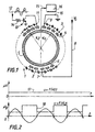
- FIG. 1 shows an encoder comprising in a known manner a track resistive 1.
- Track 1 is here formed of a set of discrete resistors 2 whose interconnections 3 are connected to studs 4 for sampling voltage. This track could however also be carried out so continuous, for example by screen printing, the tension then being directly taken from the runway.
- a conductive track 5 is produced concentrically with the track 1.
- a cursor not shown, rotatably mounted in the center of tracks 1 and 5 and whose angular position must be measured, carries a brush 6 connecting the stud corresponding to this position on track 5.
- the midpoint 7 of the resistive track 1 is connected to the supply voltage V 0 by a line 8.
- One of the ends 9 of track 1 is connected to ground by a line 10. Its other end 11 is connected to an alternating voltage, here the sector 12, via a switch 13.
- the switch 13 is in the present case made up of a transistor whose the collector is connected to point 11, whose emitter is connected to ground, and whose the base is connected to the sector by means of a resistor 14.
- the conductive track 5 is connected by a line 15 to the input analog of a microcontroller 16.
- the switch 13 is not permanently closed since the base of the transistor is alternately brought to positive and then negative voltages. The transistor is therefore alternately saturated and then blocked. As a result, the voltage u g read on the studs located, in FIG. 1, to the left of the midpoint 7, is modulated into slots as shown in 18 in FIG. 2.
- the microcontroller will recognize on which half of the resistive track is the brush 6 by the shape of the tension noted on track 5.
Landscapes
- Physics & Mathematics (AREA)
- General Physics & Mathematics (AREA)
- Transmission And Conversion Of Sensor Element Output (AREA)
- Organic Low-Molecular-Weight Compounds And Preparation Thereof (AREA)
- Measuring Pulse, Heart Rate, Blood Pressure Or Blood Flow (AREA)
- Error Detection And Correction (AREA)
- Compression, Expansion, Code Conversion, And Decoders (AREA)
- Electrophonic Musical Instruments (AREA)
- Analogue/Digital Conversion (AREA)
Claims (5)
- Analoger Winkelcodierer mit einer Widerstandsbahn (1) und einer mit dieser Widerstandsbahn verbundenen Abtastbürste (6), mit Mitteln (10, 12) um das erste (9) und das zweite (11) Ende der Widerstandsbahn jeweils an eine erste und eine zweite Spannung anzuschließen, und mit Mitteln (5, 15, 16) um die Spannung des Punktes der Widerstandsbahn am Kontakt der Abtastbürste abzulesen, dadurch gekennzeichnet, dass er Mittel (8) zur Verbindung eines anderen Punktes (7) der Widerstandsbahn mit einer dritten Spannung und Mittel (13) zur Variation mindestens der besagten ersten oder zweiten Spannung aufweist, wobei die besagte dritte Spannung gleich bleibt.
- Codierer nach Anspruch 1, wobei eine der besagten ersten oder zweiten Spannung unveränderlich ist.
- Codierer nach einem der Ansprüche 1 und 2, wobei mindestens eine der besagten erste oder zweite Spannung als Rechteckimpuls moduliert ist.
- Codierer nach einem der Ansprüche 1 bis 3, wobei besagter anderer Punkt sich exakt in der Mitte der Widerstandsbahn befindet.
- Codierer nach einem der Ansprüche 1 bis 3, mit einer konzentrisch zur Widerstandsbahn liegenden Leiterbahn (5), wobei die Abtastbürste einen Punkt der Widerstandsbahn mit der Leiterbahn verbindet, und die Spannung des Punktes der Widerstandsbahn am Kontakt der Abtastbürste auf der leitenden Spur abgelesen wird.
Applications Claiming Priority (3)
| Application Number | Priority Date | Filing Date | Title |
|---|---|---|---|
| FR9704194 | 1997-04-07 | ||
| FR9704194A FR2761795B1 (fr) | 1997-04-07 | 1997-04-07 | Codeur angulaire analogique |
| PCT/FR1998/000695 WO1998045666A1 (fr) | 1997-04-07 | 1998-04-07 | Codeur angulaire analogique |
Publications (2)
| Publication Number | Publication Date |
|---|---|
| EP0974040A1 EP0974040A1 (de) | 2000-01-26 |
| EP0974040B1 true EP0974040B1 (de) | 2002-07-24 |
Family
ID=9505575
Family Applications (1)
| Application Number | Title | Priority Date | Filing Date |
|---|---|---|---|
| EP98920575A Expired - Lifetime EP0974040B1 (de) | 1997-04-07 | 1998-04-07 | Anologer winkelcodierer |
Country Status (7)
| Country | Link |
|---|---|
| US (1) | US6567033B1 (de) |
| EP (1) | EP0974040B1 (de) |
| AT (1) | ATE221187T1 (de) |
| DE (1) | DE69806744T2 (de) |
| DK (1) | DK0974040T3 (de) |
| FR (1) | FR2761795B1 (de) |
| WO (1) | WO1998045666A1 (de) |
Families Citing this family (4)
| Publication number | Priority date | Publication date | Assignee | Title |
|---|---|---|---|---|
| FR2832215B1 (fr) * | 2001-11-14 | 2004-02-20 | Crouzet Appliance Controls | Circuit imprime pour codeur angulaire analogique |
| FR3055959B1 (fr) * | 2016-09-13 | 2018-10-12 | Ntn Snr Roulements | Systeme de determination d’au moins un parametre de rotation d’un organe tournant |
| NO20190070A1 (en) * | 2019-01-18 | 2020-07-20 | C6 Tech As | Resistive position sensor |
| EP4086586A1 (de) * | 2021-05-03 | 2022-11-09 | Vishay MCB Industrie S.A.S. | Positionscodierer |
Family Cites Families (12)
| Publication number | Priority date | Publication date | Assignee | Title |
|---|---|---|---|---|
| US3205365A (en) * | 1961-12-28 | 1965-09-07 | Baldwin Co D H | Photoelectric potentiometer actuated by position of a light spot |
| US3982106A (en) * | 1973-05-14 | 1976-09-21 | Contraves Ag | System for measuring the longitudinal or angular displacement of a movable component |
| GB1477508A (en) * | 1974-08-21 | 1977-06-22 | Rank Organisation Ltd | Measuring apparatus |
| DE2654238A1 (de) * | 1976-11-30 | 1978-06-01 | Albrecht Broemme | Analoger linearer direktproportionaler mechanisch-elektrischer drehwinkelgeber fuer unendliche drehwinkel |
| US4628316A (en) * | 1984-03-02 | 1986-12-09 | Chrysler Motors Corporation | Temperature compensation circuit and method for position sensors |
| US4599605A (en) * | 1985-01-09 | 1986-07-08 | Illinois Tool Works Inc. | Electrical encoding device |
| US4849680A (en) * | 1986-11-07 | 1989-07-18 | Kabushiki Kaisha Empire Airport Service | Encoder |
| US4942394A (en) * | 1987-12-21 | 1990-07-17 | Pitney Bowes Inc. | Hall effect encoder apparatus |
| GB2228835B (en) * | 1989-01-23 | 1993-03-31 | Precision Varionics Limited | Improvements in or relating to potentiometers |
| US5438330A (en) * | 1991-10-28 | 1995-08-01 | Nikon Corporation | Absolute encoder |
| FR2684758B1 (fr) * | 1991-12-09 | 1997-03-28 | Alcatel Satmam | Capteur de position angulaire a piste resistive continue fermee, et procede de mesure correspondant. |
| DE19639316A1 (de) * | 1996-09-25 | 1998-03-26 | Heidenhain Gmbh Dr Johannes | Positionsmeßsystem und Meßverfahren |
-
1997
- 1997-04-07 FR FR9704194A patent/FR2761795B1/fr not_active Expired - Lifetime
-
1998
- 1998-04-07 DE DE69806744T patent/DE69806744T2/de not_active Expired - Fee Related
- 1998-04-07 EP EP98920575A patent/EP0974040B1/de not_active Expired - Lifetime
- 1998-04-07 AT AT98920575T patent/ATE221187T1/de active
- 1998-04-07 WO PCT/FR1998/000695 patent/WO1998045666A1/fr not_active Ceased
- 1998-04-07 DK DK98920575T patent/DK0974040T3/da active
- 1998-04-07 US US09/402,447 patent/US6567033B1/en not_active Expired - Fee Related
Also Published As
| Publication number | Publication date |
|---|---|
| FR2761795A1 (fr) | 1998-10-09 |
| WO1998045666A1 (fr) | 1998-10-15 |
| DK0974040T3 (da) | 2002-11-18 |
| FR2761795B1 (fr) | 1999-06-25 |
| DE69806744T2 (de) | 2003-03-13 |
| DE69806744D1 (de) | 2002-08-29 |
| ATE221187T1 (de) | 2002-08-15 |
| US6567033B1 (en) | 2003-05-20 |
| EP0974040A1 (de) | 2000-01-26 |
Similar Documents
| Publication | Publication Date | Title |
|---|---|---|
| EP0765039B1 (de) | Drehwinkelgeber | |
| EP0271436B1 (de) | Kapazitiver Weggeber | |
| CH679347A5 (de) | ||
| JPH05172585A (ja) | 回転変位測定装置 | |
| EP0546907B1 (de) | Winkelposition-Sensor mit fortlaufender geschlossener Widerstandsspur und Messverfahren dafür | |
| FR2769088A1 (fr) | Capteur digital de position relative | |
| EP0974040B1 (de) | Anologer winkelcodierer | |
| FR2478859A1 (fr) | Systeme d'enregistrement a laser | |
| EP1577645B1 (de) | Optischer Encoder | |
| EP0148518A1 (de) | Vorrichtung zur Erzeugung eines elektrischen Geschwindigkeitssignales | |
| FR2520529A1 (fr) | Procede et montage de correlation a grande vitesse | |
| FR2482398A1 (fr) | Magnetoscope a balayage helicoidal a tracage automatique des tetes | |
| CH621295A5 (de) | ||
| US6020967A (en) | Differential displacement optical sensor | |
| US7257072B2 (en) | Digital audio data reproducing system | |
| FR2507413A1 (fr) | Convertisseur analogique-numerique ayant un circuit d'auto-polarisation | |
| JPH1038557A (ja) | 多回転体の回転角検出装置 | |
| EP0384089B1 (de) | Drehbarer potentiometrischer Umsetzer | |
| FR2757628A1 (fr) | Procede et dispositif de mesure numerique de positions angulaires | |
| FR2679648A1 (fr) | Transmetteur analogique de position et de sens de rotation. | |
| EP1756526A1 (de) | Einrichtung und verfahren zur bestimmung der position eines motors | |
| CH679086A5 (de) | ||
| JPH1047952A (ja) | 回転角検出装置 | |
| FR2832215A1 (fr) | Circuit imprime pour codeur angulaire analogique | |
| CA2303629C (en) | Differential displacement optical sensor - ii |
Legal Events
| Date | Code | Title | Description |
|---|---|---|---|
| PUAI | Public reference made under article 153(3) epc to a published international application that has entered the european phase |
Free format text: ORIGINAL CODE: 0009012 |
|
| 17P | Request for examination filed |
Effective date: 19991021 |
|
| AK | Designated contracting states |
Kind code of ref document: A1 Designated state(s): AT BE CH DE DK ES FI FR GB GR IE IT LI LU MC NL PT SE |
|
| GRAG | Despatch of communication of intention to grant |
Free format text: ORIGINAL CODE: EPIDOS AGRA |
|
| 17Q | First examination report despatched |
Effective date: 20010925 |
|
| GRAG | Despatch of communication of intention to grant |
Free format text: ORIGINAL CODE: EPIDOS AGRA |
|
| GRAH | Despatch of communication of intention to grant a patent |
Free format text: ORIGINAL CODE: EPIDOS IGRA |
|
| GRAH | Despatch of communication of intention to grant a patent |
Free format text: ORIGINAL CODE: EPIDOS IGRA |
|
| GRAA | (expected) grant |
Free format text: ORIGINAL CODE: 0009210 |
|
| AK | Designated contracting states |
Kind code of ref document: B1 Designated state(s): AT BE CH DE DK ES FI FR GB GR IE IT LI LU MC NL PT SE |
|
| PG25 | Lapsed in a contracting state [announced via postgrant information from national office to epo] |
Ref country code: NL Free format text: LAPSE BECAUSE OF FAILURE TO SUBMIT A TRANSLATION OF THE DESCRIPTION OR TO PAY THE FEE WITHIN THE PRESCRIBED TIME-LIMIT Effective date: 20020724 Ref country code: IE Free format text: LAPSE BECAUSE OF FAILURE TO SUBMIT A TRANSLATION OF THE DESCRIPTION OR TO PAY THE FEE WITHIN THE PRESCRIBED TIME-LIMIT Effective date: 20020724 Ref country code: GR Free format text: LAPSE BECAUSE OF FAILURE TO SUBMIT A TRANSLATION OF THE DESCRIPTION OR TO PAY THE FEE WITHIN THE PRESCRIBED TIME-LIMIT Effective date: 20020724 Ref country code: GB Free format text: LAPSE BECAUSE OF FAILURE TO SUBMIT A TRANSLATION OF THE DESCRIPTION OR TO PAY THE FEE WITHIN THE PRESCRIBED TIME-LIMIT Effective date: 20020724 Ref country code: FI Free format text: LAPSE BECAUSE OF FAILURE TO SUBMIT A TRANSLATION OF THE DESCRIPTION OR TO PAY THE FEE WITHIN THE PRESCRIBED TIME-LIMIT Effective date: 20020724 Ref country code: AT Free format text: LAPSE BECAUSE OF FAILURE TO SUBMIT A TRANSLATION OF THE DESCRIPTION OR TO PAY THE FEE WITHIN THE PRESCRIBED TIME-LIMIT Effective date: 20020724 |
|
| REF | Corresponds to: |
Ref document number: 221187 Country of ref document: AT Date of ref document: 20020815 Kind code of ref document: T |
|
| REG | Reference to a national code |
Ref country code: GB Ref legal event code: FG4D Free format text: NOT ENGLISH |
|
| REG | Reference to a national code |
Ref country code: CH Ref legal event code: EP |
|
| REG | Reference to a national code |
Ref country code: IE Ref legal event code: FG4D Free format text: FRENCH |
|
| REF | Corresponds to: |
Ref document number: 69806744 Country of ref document: DE Date of ref document: 20020829 |
|
| PG25 | Lapsed in a contracting state [announced via postgrant information from national office to epo] |
Ref country code: SE Free format text: LAPSE BECAUSE OF FAILURE TO SUBMIT A TRANSLATION OF THE DESCRIPTION OR TO PAY THE FEE WITHIN THE PRESCRIBED TIME-LIMIT Effective date: 20021024 Ref country code: PT Free format text: LAPSE BECAUSE OF FAILURE TO SUBMIT A TRANSLATION OF THE DESCRIPTION OR TO PAY THE FEE WITHIN THE PRESCRIBED TIME-LIMIT Effective date: 20021024 |
|
| REG | Reference to a national code |
Ref country code: DK Ref legal event code: T3 |
|
| NLV1 | Nl: lapsed or annulled due to failure to fulfill the requirements of art. 29p and 29m of the patents act | ||
| GBV | Gb: ep patent (uk) treated as always having been void in accordance with gb section 77(7)/1977 [no translation filed] |
Effective date: 20020724 |
|
| PG25 | Lapsed in a contracting state [announced via postgrant information from national office to epo] |
Ref country code: ES Free format text: LAPSE BECAUSE OF FAILURE TO SUBMIT A TRANSLATION OF THE DESCRIPTION OR TO PAY THE FEE WITHIN THE PRESCRIBED TIME-LIMIT Effective date: 20030130 |
|
| REG | Reference to a national code |
Ref country code: IE Ref legal event code: FD4D Ref document number: 0974040E Country of ref document: IE |
|
| PG25 | Lapsed in a contracting state [announced via postgrant information from national office to epo] |
Ref country code: LU Free format text: LAPSE BECAUSE OF NON-PAYMENT OF DUE FEES Effective date: 20030407 |
|
| PG25 | Lapsed in a contracting state [announced via postgrant information from national office to epo] |
Ref country code: MC Free format text: LAPSE BECAUSE OF NON-PAYMENT OF DUE FEES Effective date: 20030430 Ref country code: LI Free format text: LAPSE BECAUSE OF NON-PAYMENT OF DUE FEES Effective date: 20030430 Ref country code: CH Free format text: LAPSE BECAUSE OF NON-PAYMENT OF DUE FEES Effective date: 20030430 Ref country code: BE Free format text: LAPSE BECAUSE OF NON-PAYMENT OF DUE FEES Effective date: 20030430 |
|
| PLBE | No opposition filed within time limit |
Free format text: ORIGINAL CODE: 0009261 |
|
| STAA | Information on the status of an ep patent application or granted ep patent |
Free format text: STATUS: NO OPPOSITION FILED WITHIN TIME LIMIT |
|
| 26N | No opposition filed |
Effective date: 20030425 |
|
| BERE | Be: lapsed |
Owner name: S.A. *CROUZET APPLIANCE CONTROLS Effective date: 20030430 |
|
| REG | Reference to a national code |
Ref country code: CH Ref legal event code: PL |
|
| PG25 | Lapsed in a contracting state [announced via postgrant information from national office to epo] |
Ref country code: FR Free format text: LAPSE BECAUSE OF NON-PAYMENT OF DUE FEES Effective date: 20031231 |
|
| REG | Reference to a national code |
Ref country code: FR Ref legal event code: ST |
|
| PGFP | Annual fee paid to national office [announced via postgrant information from national office to epo] |
Ref country code: IT Payment date: 20060430 Year of fee payment: 9 |
|
| PGFP | Annual fee paid to national office [announced via postgrant information from national office to epo] |
Ref country code: DE Payment date: 20070405 Year of fee payment: 10 |
|
| PGFP | Annual fee paid to national office [announced via postgrant information from national office to epo] |
Ref country code: DK Payment date: 20070416 Year of fee payment: 10 |
|
| REG | Reference to a national code |
Ref country code: DK Ref legal event code: EBP |
|
| PG25 | Lapsed in a contracting state [announced via postgrant information from national office to epo] |
Ref country code: DE Free format text: LAPSE BECAUSE OF NON-PAYMENT OF DUE FEES Effective date: 20081101 |
|
| PG25 | Lapsed in a contracting state [announced via postgrant information from national office to epo] |
Ref country code: DK Free format text: LAPSE BECAUSE OF NON-PAYMENT OF DUE FEES Effective date: 20080430 |
|
| PG25 | Lapsed in a contracting state [announced via postgrant information from national office to epo] |
Ref country code: IT Free format text: LAPSE BECAUSE OF NON-PAYMENT OF DUE FEES Effective date: 20070407 |