EP0973967B1 - Method and apparatus for distributing long fibers - Google Patents
Method and apparatus for distributing long fibers Download PDFInfo
- Publication number
- EP0973967B1 EP0973967B1 EP98925471A EP98925471A EP0973967B1 EP 0973967 B1 EP0973967 B1 EP 0973967B1 EP 98925471 A EP98925471 A EP 98925471A EP 98925471 A EP98925471 A EP 98925471A EP 0973967 B1 EP0973967 B1 EP 0973967B1
- Authority
- EP
- European Patent Office
- Prior art keywords
- fibers
- chute
- metering belt
- elongate members
- metering
- Prior art date
- Legal status (The legal status is an assumption and is not a legal conclusion. Google has not performed a legal analysis and makes no representation as to the accuracy of the status listed.)
- Expired - Lifetime
Links
- 239000000835 fiber Substances 0.000 title claims description 162
- 238000000034 method Methods 0.000 title claims description 16
- 230000002787 reinforcement Effects 0.000 claims description 27
- 238000009827 uniform distribution Methods 0.000 claims description 8
- 238000007599 discharging Methods 0.000 claims description 4
- 239000000463 material Substances 0.000 description 14
- 238000009826 distribution Methods 0.000 description 8
- 230000008569 process Effects 0.000 description 5
- 239000007788 liquid Substances 0.000 description 4
- 239000011347 resin Substances 0.000 description 4
- 229920005989 resin Polymers 0.000 description 4
- 239000002131 composite material Substances 0.000 description 3
- 239000003365 glass fiber Substances 0.000 description 3
- 230000005484 gravity Effects 0.000 description 3
- 230000008901 benefit Effects 0.000 description 2
- 230000015572 biosynthetic process Effects 0.000 description 2
- 238000000576 coating method Methods 0.000 description 2
- 230000000694 effects Effects 0.000 description 2
- 239000013305 flexible fiber Substances 0.000 description 2
- 239000002557 mineral fiber Substances 0.000 description 2
- 238000012856 packing Methods 0.000 description 2
- 229910001220 stainless steel Inorganic materials 0.000 description 2
- 239000010935 stainless steel Substances 0.000 description 2
- 238000003860 storage Methods 0.000 description 2
- 244000198134 Agave sisalana Species 0.000 description 1
- 229920000049 Carbon (fiber) Polymers 0.000 description 1
- 239000004593 Epoxy Substances 0.000 description 1
- 229920000271 Kevlar® Polymers 0.000 description 1
- 241000208202 Linaceae Species 0.000 description 1
- 235000004431 Linum usitatissimum Nutrition 0.000 description 1
- 229910000831 Steel Inorganic materials 0.000 description 1
- 230000004888 barrier function Effects 0.000 description 1
- 239000011230 binding agent Substances 0.000 description 1
- 230000005540 biological transmission Effects 0.000 description 1
- 239000004917 carbon fiber Substances 0.000 description 1
- 238000004140 cleaning Methods 0.000 description 1
- 150000001875 compounds Chemical class 0.000 description 1
- 230000001419 dependent effect Effects 0.000 description 1
- 229920001971 elastomer Polymers 0.000 description 1
- 230000005611 electricity Effects 0.000 description 1
- 230000003116 impacting effect Effects 0.000 description 1
- 238000009776 industrial production Methods 0.000 description 1
- 229910052500 inorganic mineral Inorganic materials 0.000 description 1
- 230000003993 interaction Effects 0.000 description 1
- 239000011159 matrix material Substances 0.000 description 1
- 239000011707 mineral Substances 0.000 description 1
- 229920001778 nylon Polymers 0.000 description 1
- 229920000728 polyester Polymers 0.000 description 1
- 229920000642 polymer Polymers 0.000 description 1
- 229920002635 polyurethane Polymers 0.000 description 1
- 239000004814 polyurethane Substances 0.000 description 1
- 229920002689 polyvinyl acetate Polymers 0.000 description 1
- 239000011118 polyvinyl acetate Substances 0.000 description 1
- 238000002407 reforming Methods 0.000 description 1
- 239000011208 reinforced composite material Substances 0.000 description 1
- 230000003014 reinforcing effect Effects 0.000 description 1
- 230000004044 response Effects 0.000 description 1
- 239000002002 slurry Substances 0.000 description 1
- 238000009987 spinning Methods 0.000 description 1
- 230000003068 static effect Effects 0.000 description 1
- 239000010959 steel Substances 0.000 description 1
- 239000000758 substrate Substances 0.000 description 1
- 230000000007 visual effect Effects 0.000 description 1
Images


Classifications
-
- D—TEXTILES; PAPER
- D04—BRAIDING; LACE-MAKING; KNITTING; TRIMMINGS; NON-WOVEN FABRICS
- D04H—MAKING TEXTILE FABRICS, e.g. FROM FIBRES OR FILAMENTARY MATERIAL; FABRICS MADE BY SUCH PROCESSES OR APPARATUS, e.g. FELTS, NON-WOVEN FABRICS; COTTON-WOOL; WADDING ; NON-WOVEN FABRICS FROM STAPLE FIBRES, FILAMENTS OR YARNS, BONDED WITH AT LEAST ONE WEB-LIKE MATERIAL DURING THEIR CONSOLIDATION
- D04H3/00—Non-woven fabrics formed wholly or mainly of yarns or like filamentary material of substantial length
- D04H3/02—Non-woven fabrics formed wholly or mainly of yarns or like filamentary material of substantial length characterised by the method of forming fleeces or layers, e.g. reorientation of yarns or filaments
-
- D—TEXTILES; PAPER
- D04—BRAIDING; LACE-MAKING; KNITTING; TRIMMINGS; NON-WOVEN FABRICS
- D04H—MAKING TEXTILE FABRICS, e.g. FROM FIBRES OR FILAMENTARY MATERIAL; FABRICS MADE BY SUCH PROCESSES OR APPARATUS, e.g. FELTS, NON-WOVEN FABRICS; COTTON-WOOL; WADDING ; NON-WOVEN FABRICS FROM STAPLE FIBRES, FILAMENTS OR YARNS, BONDED WITH AT LEAST ONE WEB-LIKE MATERIAL DURING THEIR CONSOLIDATION
- D04H1/00—Non-woven fabrics formed wholly or mainly of staple fibres or like relatively short fibres
- D04H1/70—Non-woven fabrics formed wholly or mainly of staple fibres or like relatively short fibres characterised by the method of forming fleeces or layers, e.g. reorientation of fibres
- D04H1/72—Non-woven fabrics formed wholly or mainly of staple fibres or like relatively short fibres characterised by the method of forming fleeces or layers, e.g. reorientation of fibres the fibres being randomly arranged
-
- B—PERFORMING OPERATIONS; TRANSPORTING
- B29—WORKING OF PLASTICS; WORKING OF SUBSTANCES IN A PLASTIC STATE IN GENERAL
- B29C—SHAPING OR JOINING OF PLASTICS; SHAPING OF MATERIAL IN A PLASTIC STATE, NOT OTHERWISE PROVIDED FOR; AFTER-TREATMENT OF THE SHAPED PRODUCTS, e.g. REPAIRING
- B29C70/00—Shaping composites, i.e. plastics material comprising reinforcements, fillers or preformed parts, e.g. inserts
- B29C70/04—Shaping composites, i.e. plastics material comprising reinforcements, fillers or preformed parts, e.g. inserts comprising reinforcements only, e.g. self-reinforcing plastics
- B29C70/28—Shaping operations therefor
- B29C70/40—Shaping or impregnating by compression not applied
- B29C70/50—Shaping or impregnating by compression not applied for producing articles of indefinite length, e.g. prepregs, sheet moulding compounds [SMC] or cross moulding compounds [XMC]
- B29C70/502—Shaping or impregnating by compression not applied for producing articles of indefinite length, e.g. prepregs, sheet moulding compounds [SMC] or cross moulding compounds [XMC] by first forming a mat composed of short fibres
-
- D—TEXTILES; PAPER
- D01—NATURAL OR MAN-MADE THREADS OR FIBRES; SPINNING
- D01G—PRELIMINARY TREATMENT OF FIBRES, e.g. FOR SPINNING
- D01G23/00—Feeding fibres to machines; Conveying fibres between machines
- D01G23/02—Hoppers; Delivery shoots
- D01G23/04—Hoppers; Delivery shoots with means for controlling the feed
-
- D—TEXTILES; PAPER
- D01—NATURAL OR MAN-MADE THREADS OR FIBRES; SPINNING
- D01G—PRELIMINARY TREATMENT OF FIBRES, e.g. FOR SPINNING
- D01G25/00—Lap-forming devices not integral with machines specified above
-
- D—TEXTILES; PAPER
- D04—BRAIDING; LACE-MAKING; KNITTING; TRIMMINGS; NON-WOVEN FABRICS
- D04H—MAKING TEXTILE FABRICS, e.g. FROM FIBRES OR FILAMENTARY MATERIAL; FABRICS MADE BY SUCH PROCESSES OR APPARATUS, e.g. FELTS, NON-WOVEN FABRICS; COTTON-WOOL; WADDING ; NON-WOVEN FABRICS FROM STAPLE FIBRES, FILAMENTS OR YARNS, BONDED WITH AT LEAST ONE WEB-LIKE MATERIAL DURING THEIR CONSOLIDATION
- D04H3/00—Non-woven fabrics formed wholly or mainly of yarns or like filamentary material of substantial length
- D04H3/02—Non-woven fabrics formed wholly or mainly of yarns or like filamentary material of substantial length characterised by the method of forming fleeces or layers, e.g. reorientation of yarns or filaments
- D04H3/03—Non-woven fabrics formed wholly or mainly of yarns or like filamentary material of substantial length characterised by the method of forming fleeces or layers, e.g. reorientation of yarns or filaments at random
-
- D—TEXTILES; PAPER
- D04—BRAIDING; LACE-MAKING; KNITTING; TRIMMINGS; NON-WOVEN FABRICS
- D04H—MAKING TEXTILE FABRICS, e.g. FROM FIBRES OR FILAMENTARY MATERIAL; FABRICS MADE BY SUCH PROCESSES OR APPARATUS, e.g. FELTS, NON-WOVEN FABRICS; COTTON-WOOL; WADDING ; NON-WOVEN FABRICS FROM STAPLE FIBRES, FILAMENTS OR YARNS, BONDED WITH AT LEAST ONE WEB-LIKE MATERIAL DURING THEIR CONSOLIDATION
- D04H5/00—Non woven fabrics formed of mixtures of relatively short fibres and yarns or like filamentary material of substantial length
- D04H5/08—Non woven fabrics formed of mixtures of relatively short fibres and yarns or like filamentary material of substantial length characterised by the method of forming fleeces or layers, e.g. reorientation of fibres or yarns
Definitions
- This invention relates in general to distributing fibers for such purposes as making mats of reinforcement fibers or sheet like composite compounds. More particularly, the invention relates to distributing reinforcement fibers generally uniformly on a collecting surface to form evenly reinforced mats or composite sheets. The invention will be useful for making such products as glass fiber reinforcement mats and glass fiber reinforced composite materials.
- the reinforcement fibers can be introduced into the product in a variety of ways. From the standpoint of industrial production, a major method of introducing fibers into matrices involves the formation of a mat of reinforcement fibers.
- the reinforced products generally referred to as "composites", can be used for numerous end uses, including automobile, industrial and domestic equipment as well as electronic components.
- the reinforcement fibers can be of any material, length, diameter or shape suitable to provide the resin matrix with superior properties, such as strength, stiffness and fire retardancy.
- Typical reinforcement fibers include mineral fibers, such as glass fibers, organic fibers, such as nylon fibers, and natural fibers, such as flax or sisal.
- the mineral reinforcement fibers typically have sizes or coatings, involving such polymers as polyvinyl acetate, polyurethane or epoxy.
- the formation of a reinforcing mat, and thus the distribution of reinforcemen: fibers onto a substrate or collection surface can be accomplished in several ways.
- the fibers can be mixed with a liquid and formed into a slurry, which is then moved over a porous conveyor where the liquid is removed.
- This product is known as a wet process mat or wet laid mat.
- a problem with the wet process is that it requires enormous equipment with associated very high capital investments, and it consumes a significant amount of erergy to drive the liquid from the system. The process also requires extensive cleaning to protect the environment.
- Another process for distributing fibers is to air lay or air blow them onto a collection surface.
- the desired effect is uniform distribution and a random orientation, much like the randomness of a snowstorm.
- a problem with the air laid mat process is that it is difficult to control metering of the fibers (the output rate as a function of time) to allow uniformity along the line axis or machine direction of the mat. It is also difficult to achieve uniform distribution of the fibers transverse to the line direction or machine direction, particularly when the input material is in the form of discontinuous fibers of high aspect ratio (length versus diameter).
- a uniform air laid distribution of fibers is particularly difficult for wide collection surfaces, such as surfaces wider than one meter.
- the apparatus of the invention includes a chute for supplying reinforcement fibers, where the chute has an outlet end.
- a metering belt is mounted for endless travel along a first path at the outlet end of the chute.
- the metering belt has elongate members with tips extending outwardly from the metering belt, thereby defining a volume between the tips and the metering belt, the tips of the metering belt running close to the chute so that the fibers having penetrated the volume formed by the elongate members are carried away by the metering belt.
- the metering belt is also mounted for endless travel along a second path which guides the metering belt around a curved surface. This causes adjacent elongate members to spread apart and diverge from each other, thereby causing the fibers to be discharged from the metering belt.
- the apparatus also includes a collection surface for receiving the discharged fibers.
- a method of distributing reinforcement fibers including discharging reinforcement fibers into a chute having an outlet end, withdrawing the fibers from the chute and placing them on a metering belt which is moving along a first path generally parallel to the outlet end of the chute.
- the metering belt has elongate members with tips extending outwardly from the metering belt, thereby defining a volume between the tips and the metering belt. The tips of the metering belt are moved close to the chute and the fibers having penetrated the volume formed by the elongate members are carried away by the metering belt.
- the fibers are discharged from the metering belt by moving the belt along a second path around a curved surface, where travel of the metering belt around the curved surface causes adjacent elongate members to spread apart and diverge from each other, thereby releasing the fibers.
- the discharged fibers are received on a collection, surface.
- Fig. 1 illustrates apparatus for distributing reinforcement fibers 10.
- the fibers may be supplied from any source, such as an in-line supply from a fiber forming operation, or such as the storage silo 12 shown in the drawing.
- the storage silo is connected to a transfer conveyor 14 which feeds the fibers onto the upper spreader 16.
- the conveyor is a belt equipped with pins similar to those that will be described below for the metering belt so that the transfer conveyor can easily extract fibers from the silo.
- the upper spreader typically includes a hopper 18 and a spreader roller 20 spinning at a higher speed than the transfer conveyor.
- the spreader roller is also provided with pins which intermesh with those of the conveyor belt.
- the sidewall or receiving wall 22 of the hopper is preferably at an angle to the vertical so that the fibers are intercepted and slide along the sloping surface into the chute 24, rather than merely fall into the chute.
- Airborne long fibers sometimes have a tendency to entangle with each other as they fall a long distance through the air thus reforming clumps and disturbing the good uniform distribution which is sought.
- the reinforcement fiber can be made of any material suitable for reinforcement purposes.
- a preferred material is a long fiber chopped strand, which can be obtained from Owens Coming, Toledo, Ohio, although other mineral fibers and organic fibers, such as polyester, Kevlar® and carbon fibers, can be used with the invention. It is to be understood that the reinforcement fibers can be a single filament (monofilament), although for most reinforcement applications the fibers are chopped bundles containing numerous filaments.
- a preferred material for the fibers 10 is a chopped strand having about 50 to about 200 filaments in each bundle, and more preferably having about 100 filaments in each bundle.
- the bundles of the fibers 10 preferably have a length within the range of from about 20 to about 100 mm, and have a diameter of about 0.5 mm, although the bundles may be somewhat flattened to have cross-sectional dimensions of about 1 mm on the long axis and about 0.25 mm on the short axis.
- the chute can be any conduit for supplying and directing the fibers along the path toward the ultimate metering device.
- the fibers preferably move by gravity in the chute toward the outlet end 26 at the bottom of the chute.
- a mechanical or pneumatic means can be used to urge the fibers toward the bottom of the chute. It is important not to overly compress the fibers in the chute because that may cause some of the fibers to become entangled and result in greater nonuniformities in the resulting distribution of the fibers.
- the rate at which the fibers are removed from the chute 24 is a function of the pressure on the fibers at the bottom of the chute. If the fibers are moved through the chute merely by gravity, this pressure on the fibers should be a function of the height of the column of fibers and of their apparent density of natural stacking in the chute. By operating with a constant height of fibers in the chute, the pressure of the fibers at the bottom of the chute can be made generally constant, thereby helping to achieve good uniformity in the produced mat both in the line or machine direction and the transverse or cross-machine direction of the product.
- a typical pressure of the fibers at the bottom of the chute is within the range of from about 2,000 Pa to about 20,000 Pa, and preferably about 6,000 Pa.
- the chute can be provided with a vertical array 28 of light sources which is aligned with a corresponding series of photocells 30.
- the fibers in the chute block the transmission of light from the light sources to the photocells, thereby providing an indication of the height of the column of fibers in the chute.
- Other methods such as using sonar or providing for visual observation, can be used to determine the height of the fibers in the chute.
- To ensure a constant height of material in the chute one can make use of a closed loop system between sensors measuring the height of material and the motor driving the transfer conveyor 14.
- the supply rate of fibers into the chute is typically adjusted in response to the measured height of the fibers so as to maintain this height at a constant level.
- the control of the height of the fibers and the system of uniform packing of fibers, provided by the upper spreader 16 and the angled receiving wall 22, enable the pressure of the fibers to be controlled, leading to a uniform withdrawal of fibers from the chute and a more uniform distribution of fibers in the ultimate product.
- the metering belt 32 withdraws fibers from the chute and carries them away for later discharge.
- the metering belt 32 is mounted for endless travel and can be powered by any suitable means, such as an electric motor, not shown.
- the metering belt travels along a first path 34 at the outlet end 26 of the chute.
- the metering belt has numerous elongate members, such as pins 36 having tips 38, projecting out or extending outwardly to contact and engage the fibers at the outlet end of the chute.
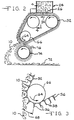
- the pins extending outwardly from the metering belt form or define a volume 40 between the tips and the metering belt, as shown most clearly in Fig. 5.
- the first path of the tips runs close to the outlet end, and the fibers that have penetrated the volume are withdrawn from the chute and carried away by the metering belt.
- the metering belt can be made of any material that is flexible and suitable for endless travel and for mounting the pins.
- a preferred material is a reinforced rubber material, although an open mesh steel belt can also be used.
- the pins 36 can be any elongate member extending outwardly from the belt suitable for engaging the fibers.
- the pins can be made of any material, such as stainless steel.
- the pins are conical in shape, ending in the tips 38.
- the pins project about 30 mm from the surface of the metering belt, and taper or are reduced in diameter from a diameter of about 6 mm at the base of the pin to a much smaller dimension at the tip, such as a dull point with a diameter of about 0.5 mm.
- the amount of fibers withdrawn from the chute is dependent not only on the pressure of the fibers at the bottom of the chute, but also on the packing of the pins.
- Another factor determining the amount of fibers withdrawn by the metering belt is the geometry of the pins, mainly the sharpness of the taper of the pins. The smaller the angle of taper of the pins, the more fibers will be grabbed by the pins. Where the pins are too closely packed together on the metering belt, the fibers will not be grabbed by the pins, and instead will merely rest on the top of the pins. Therefore, fewer of the fibers will penetrate into the volume 40.
- the pins are spaced too far apart, the pins will not be able to adequately perform the function of pulling homogeneous quantities of fibers, and high density concentrations of fibers positioned between the pins will be carried away by the metering belt.
- the pins will be spaced at a distance from each other equal to about one-half the length of the fibers.
- a doctor blade 44 is positioned to meter the amount of fibers 10 being carried away per unit of time by the metering belt.
- the doctor blade can be a conventional straight edged barrier, or can be serrated to provide a greater interaction between the pins 36 and the doctor blade 44, as shown in Figs. 4 and 5.
- the doctor blade defines a gap 46 between the doctor blade and the metering belt 32.
- the doctor blade can be made of any suitable material such as stainless steel, which has the advantage of being able to be grounded to discharge static electricity which might otherwise be built up.
- the doctor blade can be mounted in any suitable manner, such as by bolting it onto the wall of the chute 24. Preferably, the doctor blade is adjustably mounted to enable its vertical adjustment.
- the serrated doctor blade 44 has a series of projections 48 defining slots 50.
- the uppermost portions 52 of the slots 50 define an overall gap 54, which is the maximum clearance between the doctor blade and the metering belt 32.
- the pins 36 in the metering belt are aligned with the slots so that the pins do not interfere with the projections 48 of the doctor blade. In this manner, the pins 36 can extend up toward the chute outlet 26 to an extent that the pins overlap the projections 48 without actually contacting the projections.
- the amount of overlap is indicated at 56 in Fig. 5. A typical amount of overlap is about 10 mm.
- the projections 48 need not be merely downwardly projecting teeth or spikes, but can be elongated for an extended length along the first path 34, in the line or machine direction, so that they are shaped like fins.
- the projections 48 will generally be shaped with a sloped profile 60 so that they extend from the doctor blade 44 toward the metering belt with an increasing height 62 along the direction of the first path 34. This will allow the fibers 10 to be gradually engaged by the pins 36 as the pins pass through the slots 50. As the metering belt travels across the chute, the fibers will be gradually pressed down onto the pins.
- the metering belt 32 picks up the fibers as the metering belt travels along the first path, the metering belt travels along a second path 64 which guides the metering belt to bend around lower roller 66 with the pins in a downward orientation (see Figs. 3 and 4).
- roller 66 is shown, it is to be understood that the metering belt can be guided to bend around any curved surface as long as the result is the causing of the tips 38 of adjacent pins 36 to spread apart or diverge from each other as the metering belt travels around the curved surface.
- the maximum angle of divergence, indicated at 68 is preferably at least 5 degrees.
- the advantage of having the pins diverge while the metering belt is upside down is that the fibers 10 carried by the metering belt will be more likely to be discharged or fall off the metering belt. The release of the fibers is also facilitated by the conical nature of the pins.
- the apparatus and method of the invention enable a uniform discharge of fibers in a way not before thought possible.
- One of the problems with metering fibers heretofore is that more flexible fibers can get caught or jammed between the pins and it is difficult to remove the fibers from the pins. Therefore, typical pin metering apparatus has been effective only for relatively stiff fibers.
- pins having a conical surface according to the present invention, and the positioning of the discharge of the fibers from the metering belt at a point where the pins are diverging, enables the apparatus to handle fibers which are softer or which have more flexibility than previously thought possible.
- fibers would be limited to a length no longer than about 25 mm, and the fibers would have to be very stiff and needle-like to avoid becoming jammed during distribution.
- fibers having a flexibility found in conventional multi-filament reinforcement fibers i.e., relatively soft or flexible fibers such as a choppable roving
- fibers having a flexibility found in conventional multi-filament reinforcement fibers may be successfully distributed without substantial clogging of the pins.
- the method and apparatus of the invention also enable the use of longer fibers than previously thought possible. Fibers up to 10 cm and longer can be distributed, and possibly continuous fibers can also be so distributed.
- the discharged fibers 10 ultimately end up on the collection surface, which is indicated as conveyor belt 70 in Fig. 1.
- conveyor belt 70 in Fig. 1.
- the fibers can be formed into a mat 72, and a binder material can be added to bond the fibers together.
- resin can be applied to make a moldable material.
- the resin can be applied onto a carrier film, not shown, traveling on the conveyor belt before the fibers are of from about 5 to about 40 meters per minute, whereas the speed of the metering belt is typically about twice the speed of the conveyor belt.
- a spreader drum 74 can be positioned to receive the fibers 10 from the metering belt and deposit them on the collection surface. This will enhance the homogeneity and the randomness of the fibers in the formed mat.
- the spreader drum 74 can be provided with spikes 76 which intermesh with the pins 36 on the metering belt 34 to help discharge the fibers from the metering belt.
- the spreader drum 74 is rotating so that the spikes 76 move in opposition to the metering belt pins 36.
- the spreader drum spikes 76 are preferably longer than the pins 36 on the metering belt, and are typically about 60 mm long.
- the spreader drum spikes are generally rounded rather than sharp at their tips.
- the spreader drum can be operated at any linear speed faster than the lineal speed of the metering belt, but preferably at a linear surface speed of about ten times the linear speed of the metering belt, or about 200 meters per minute.
- the spreader drum can be of any appropriate size, preferably having a diameter within the range of from about 20 to about 40 cm.
- the chute is shown in a vertical orientation, it is to be understood that the principles of the invention can be carried out at any angle to the vertical with the chute in a horizontal position. In such an embodiment, the metering belt would travel vertically past the outlet of the chute to engage the fibers and withdraw them from the chute. Also, although only one upper spreader 16 and one spreader drum 74 are shown, more than one of each of these fiber randomizing devices can be used with the invention. Although the invention has been illustrated with chopped fibers as the reinforcement fibers being distributed, it is to be understood that the invention can be used with continuous fibers to make continuous strand mats of continuous fibers.
Landscapes
- Engineering & Computer Science (AREA)
- Textile Engineering (AREA)
- Chemical & Material Sciences (AREA)
- Composite Materials (AREA)
- Mechanical Engineering (AREA)
- Preliminary Treatment Of Fibers (AREA)
- Nonwoven Fabrics (AREA)
- Dry Formation Of Fiberboard And The Like (AREA)
Description
Claims (13)
- Apparatus (16) for distributing reinforcement fibers (10) comprising:a chute (24) for supplying reinforcement fibers, the chute having an outlet end (26);a metering belt (32) mounted for endless travel along a first path (34) at the outlet end of the chute, the metering belt having elongate members (36) with tips (38) extending outwardly from the metering belt, thereby defining a volume between the tips and the metering belt, the tips running close to the chute so that the fibers having penetrated the volume formed by the elongate members are carried away by the metering belt, the metering belt also being mounted for endless travel along a second path (64) which guides the metering belt around a curved surface (66) which causes adjacent elongate members to spread apart and diverge from each other, thereby causing the fibers to be discharged from the metering belt; anda collection surface for receiving the discharged fibers.
- Apparatus according to claim 1, wherein the elongate members (36) comprise conical pins.
- Apparatus according to claim 1 or claim 2, wherein the chute has a doctor blade (44) to define a gap between the chute and the moving elongate members to control the amount of fibers withdrawn from the chute.
- Apparatus according to claim 3, wherein the doctor blade is serrated and has a series of projections (48) and slots (50), the slots being in alignment with the elongate members (36).
- Apparatus according to of claim 3 or claim 4, wherein the height of the projections increases along the direction of the first path.
- Apparatus according to any one of claims 1 to 5, wherein the first path (34) is straight whereby the elongate members (36) are substantially parallel as they travel across the outlet end of the chute.
- Apparatus according to any one of claims 1 to 6, wherein the curved surface (66) is a roller and, where the metering belt bends around the roller, the elongate members are pointed generally downwardly.
- Apparatus according to claim 7, wherein the maximum angle of divergence of the elongate members when the metering belt travels around the roller (66) is at least 5°.
- Apparatus according to any one of claims 1 to 8, including a measuring device (28,30) to assess the height of the fibers in the chute.
- Apparatus according to any one of claims 1 to 9, including a spreader roller (20) for receiving the fibers from a source (12,14), for rearranging the fibers into a more uniform distribution, and for discharging the fibers into the chute.
- A method of distributing reinforcement fibers (10) comprising:discharging reinforcement fibers into a chute (24) having an outlet end (26);withdrawing the fibers from the chute (24) on a metering belt (32) which is moving along a first path (34) generally parallel to the outlet, the metering belt having elongate members (36) with tips (38) extending outwardly from the metering belt, thereby defining a volume between the tips and the metering belt, the tips moving close to the chute so that the fibers having penetrated the volume formed by the elongate members are carried away by the metering belt;discharging the fibers from the metering belt by moving it along a second path (64) which guides the metering belt around a curved surface (66) which causes adjacent elongate members to spread apart and diverge from each other, thereby releasing the fibers; andreceiving the discharged fibers on a collection surface (70).
- A method according to claim 11, wherein the fibers are metered from the chute with a doctor blade (44) which defines a gap between the chute and the moving elongate members to control the amount of fibers withdrawn from the chute.
- A method according to claim 11 or claim 12, wherein the elongate members are caused to diverge at a maximum angle of at least 5° when the metering belt travels along the second path.
Applications Claiming Priority (3)
| Application Number | Priority Date | Filing Date | Title |
|---|---|---|---|
| US826959 | 1997-04-09 | ||
| US08/826,959 US5873150A (en) | 1997-04-09 | 1997-04-09 | Method and apparatus for distributing long fibers |
| PCT/EP1998/002141 WO1998045518A2 (en) | 1997-04-09 | 1998-04-03 | Method and apparatus for distributing long fibers |
Publications (2)
| Publication Number | Publication Date |
|---|---|
| EP0973967A2 EP0973967A2 (en) | 2000-01-26 |
| EP0973967B1 true EP0973967B1 (en) | 2002-08-07 |
Family
ID=25247949
Family Applications (1)
| Application Number | Title | Priority Date | Filing Date |
|---|---|---|---|
| EP98925471A Expired - Lifetime EP0973967B1 (en) | 1997-04-09 | 1998-04-03 | Method and apparatus for distributing long fibers |
Country Status (7)
| Country | Link |
|---|---|
| US (1) | US5873150A (en) |
| EP (1) | EP0973967B1 (en) |
| JP (1) | JP2001522413A (en) |
| KR (1) | KR20010006186A (en) |
| AU (1) | AU7758698A (en) |
| DE (1) | DE69807056T2 (en) |
| WO (1) | WO1998045518A2 (en) |
Families Citing this family (9)
| Publication number | Priority date | Publication date | Assignee | Title |
|---|---|---|---|---|
| DE19805996A1 (en) * | 1998-02-16 | 1999-09-16 | Rolf Hesch | Device and method for producing a fiber composite |
| US6488811B1 (en) | 2001-04-30 | 2002-12-03 | Owens Corning Fiberglas Technology, Inc. | Multicomponent mats of glass fibers and natural fibers and their method of manufacture |
| CN1224741C (en) * | 2003-01-24 | 2005-10-26 | 张立文 | Feathery-needle fiber weaved article and its production method |
| US7156263B2 (en) * | 2003-02-04 | 2007-01-02 | Larry Hooper | System and method for metering fibrous material |
| US7255247B2 (en) * | 2004-12-02 | 2007-08-14 | Aylward Enterprises, Inc. | Apparatus and methods for handling pills |
| CN101307529B (en) * | 2008-04-15 | 2010-11-03 | 黄显飚 | A kind of preparation technology of air-laid fiber cotton and the fiber cotton made |
| US12590393B2 (en) | 2011-09-30 | 2026-03-31 | Owens Corning Intellectual Capital, Llc | Method of forming a web from fibrous materials |
| CN103958755B (en) | 2011-09-30 | 2018-05-25 | 欧文斯科宁知识产权资产有限公司 | Method of forming a web from a fibrous material |
| CN109368294A (en) * | 2018-11-19 | 2019-02-22 | 扬州快乐机械有限公司 | A blanking rake and paving machine |
Family Cites Families (9)
| Publication number | Priority date | Publication date | Assignee | Title |
|---|---|---|---|---|
| CH215365A (en) * | 1938-11-11 | 1941-06-30 | Glasfasern A G | Method and device for the production of fibers from glass, slag or similar substances that are plastic in heat. |
| US2890497A (en) * | 1954-03-10 | 1959-06-16 | Curlator Corp | Machine for forming random fiber webs |
| US2917787A (en) * | 1956-03-20 | 1959-12-22 | Southern Res Inst | Process and apparatus for producing non-woven sheets of fibrous materials |
| US3034180A (en) * | 1959-09-04 | 1962-05-15 | Kimberly Clark Co | Manufacture of cellulosic products |
| US4071925A (en) * | 1976-05-25 | 1978-02-07 | The United States Of America As Represented By The Secretary Of Agriculture | Apparatus for forming textile lap |
| US4280253A (en) * | 1979-03-16 | 1981-07-28 | Owens-Corning Fiberglas Corporation | Method for collecting fibrous material |
| US4741941A (en) * | 1985-11-04 | 1988-05-03 | Kimberly-Clark Corporation | Nonwoven web with projections |
| US4991264A (en) * | 1990-01-16 | 1991-02-12 | International Paper Company | Apparatus and method for use in-line with a card to enhance tensile strength in nonwoven materials |
| AT396791B (en) * | 1992-06-26 | 1993-11-25 | Fehrer Ernst | DEVICE FOR PRODUCING A FLEECE |
-
1997
- 1997-04-09 US US08/826,959 patent/US5873150A/en not_active Expired - Fee Related
-
1998
- 1998-04-03 KR KR1019997009265A patent/KR20010006186A/en not_active Withdrawn
- 1998-04-03 DE DE69807056T patent/DE69807056T2/en not_active Expired - Fee Related
- 1998-04-03 AU AU77586/98A patent/AU7758698A/en not_active Withdrawn
- 1998-04-03 WO PCT/EP1998/002141 patent/WO1998045518A2/en not_active Ceased
- 1998-04-03 EP EP98925471A patent/EP0973967B1/en not_active Expired - Lifetime
- 1998-04-03 JP JP54241098A patent/JP2001522413A/en active Pending
Also Published As
| Publication number | Publication date |
|---|---|
| DE69807056D1 (en) | 2002-09-12 |
| AU7758698A (en) | 1998-10-30 |
| EP0973967A2 (en) | 2000-01-26 |
| WO1998045518A2 (en) | 1998-10-15 |
| WO1998045518A3 (en) | 1999-01-21 |
| KR20010006186A (en) | 2001-01-26 |
| US5873150A (en) | 1999-02-23 |
| JP2001522413A (en) | 2001-11-13 |
| DE69807056T2 (en) | 2002-12-05 |
Similar Documents
| Publication | Publication Date | Title |
|---|---|---|
| US5873150A (en) | Method and apparatus for distributing long fibers | |
| US3535187A (en) | Apparatus for manufacturing nonwoven textile articles | |
| CN109312503A (en) | Partially divided fiber bundle and method for producing the same, and fiber-reinforced resin molding material using partially divided fiber bundle and method for producing the same | |
| US3376609A (en) | Method for spreading tows of continuous filaments into sheets | |
| CN109312502A (en) | Partially divided fiber bundle and method for producing the same, and fiber-reinforced resin molding material using partially divided fiber bundle and method for producing the same | |
| CN1026905C (en) | Non-Woven article made of heat-resisting material,method for manufacturing article and appartus for implementing method | |
| US20130198998A1 (en) | Laying device and laying method | |
| US3614936A (en) | Nonwoven reinforcement structure and method for producing it | |
| US5163348A (en) | Method of and apparatus for cutting fibers | |
| CN109312504A (en) | Partially divided fiber bundle and method for producing the same, and fiber-reinforced resin molding material using partially divided fiber bundle and method for producing the same | |
| US20080047657A1 (en) | System for forming reinforcement layers having cross-directionally oriented fibers | |
| TW201934827A (en) | Partially separated fiber bundle, intermediate base material, molding, and method for producing same | |
| US6735835B2 (en) | Method and apparatus for manufacturing non-woven fabrics | |
| CN109423775B (en) | Method for forming a shaped nonwoven | |
| US3515609A (en) | Method of manufacture of reinforced unwoven felts | |
| CN112831912B (en) | Production line of ultrathin coconut palm fiber flat pad and manufacturing method of coconut fiber flat pad | |
| NO840841L (en) | PROCEDURE FOR THE PREPARATION OF NON-WOVEN WATER OF FIBER | |
| CN1231630A (en) | Building material and a process and device for producing a building material | |
| KR102702466B1 (en) | Recycled carbon fiber nonwoven manufacturing system including chute carding machine | |
| SI9300389A (en) | Process and apparatus for dynamic-flow production of ductile, highly-resistant fiber mats | |
| US2584702A (en) | Method and apparatus for the production of glass fiber mats | |
| US2855634A (en) | Fibrous mat and method of making | |
| US20030107148A1 (en) | Methods of randomly dispersing chopped carbon fiber and consolidating the materials together to make a fiber reinforcement mat | |
| KR100845908B1 (en) | Mechanism and method for manufacturing mat composed of continuous yarn | |
| US3474500A (en) | Process and apparatus for forming a foam fiber batt |
Legal Events
| Date | Code | Title | Description |
|---|---|---|---|
| PUAI | Public reference made under article 153(3) epc to a published international application that has entered the european phase |
Free format text: ORIGINAL CODE: 0009012 |
|
| 17P | Request for examination filed |
Effective date: 19991103 |
|
| AK | Designated contracting states |
Kind code of ref document: A2 Designated state(s): BE DE FR GB |
|
| RAP1 | Party data changed (applicant data changed or rights of an application transferred) |
Owner name: OWENS CORNING COMPOSITES S.P.R.L. |
|
| GRAG | Despatch of communication of intention to grant |
Free format text: ORIGINAL CODE: EPIDOS AGRA |
|
| 17Q | First examination report despatched |
Effective date: 20010315 |
|
| GRAG | Despatch of communication of intention to grant |
Free format text: ORIGINAL CODE: EPIDOS AGRA |
|
| GRAG | Despatch of communication of intention to grant |
Free format text: ORIGINAL CODE: EPIDOS AGRA |
|
| GRAH | Despatch of communication of intention to grant a patent |
Free format text: ORIGINAL CODE: EPIDOS IGRA |
|
| GRAH | Despatch of communication of intention to grant a patent |
Free format text: ORIGINAL CODE: EPIDOS IGRA |
|
| GRAA | (expected) grant |
Free format text: ORIGINAL CODE: 0009210 |
|
| AK | Designated contracting states |
Kind code of ref document: B1 Designated state(s): BE DE FR GB |
|
| REG | Reference to a national code |
Ref country code: GB Ref legal event code: FG4D |
|
| REF | Corresponds to: |
Ref document number: 69807056 Country of ref document: DE Date of ref document: 20020912 |
|
| ET | Fr: translation filed | ||
| PG25 | Lapsed in a contracting state [announced via postgrant information from national office to epo] |
Ref country code: GB Free format text: LAPSE BECAUSE OF NON-PAYMENT OF DUE FEES Effective date: 20030403 |
|
| PG25 | Lapsed in a contracting state [announced via postgrant information from national office to epo] |
Ref country code: BE Free format text: LAPSE BECAUSE OF NON-PAYMENT OF DUE FEES Effective date: 20030430 |
|
| PLBE | No opposition filed within time limit |
Free format text: ORIGINAL CODE: 0009261 |
|
| STAA | Information on the status of an ep patent application or granted ep patent |
Free format text: STATUS: NO OPPOSITION FILED WITHIN TIME LIMIT |
|
| 26N | No opposition filed |
Effective date: 20030508 |
|
| BERE | Be: lapsed |
Owner name: *OWENS CORNING COMPOSITES S.P.R.L. Effective date: 20030430 |
|
| PG25 | Lapsed in a contracting state [announced via postgrant information from national office to epo] |
Ref country code: DE Free format text: LAPSE BECAUSE OF NON-PAYMENT OF DUE FEES Effective date: 20031101 |
|
| GBPC | Gb: european patent ceased through non-payment of renewal fee |
Effective date: 20030403 |
|
| PG25 | Lapsed in a contracting state [announced via postgrant information from national office to epo] |
Ref country code: FR Free format text: LAPSE BECAUSE OF NON-PAYMENT OF DUE FEES Effective date: 20031231 |
|
| REG | Reference to a national code |
Ref country code: FR Ref legal event code: ST |