EP0973010A2 - Micromechanical rotation rate sensor with coupling structure - Google Patents
Micromechanical rotation rate sensor with coupling structure Download PDFInfo
- Publication number
- EP0973010A2 EP0973010A2 EP99110812A EP99110812A EP0973010A2 EP 0973010 A2 EP0973010 A2 EP 0973010A2 EP 99110812 A EP99110812 A EP 99110812A EP 99110812 A EP99110812 A EP 99110812A EP 0973010 A2 EP0973010 A2 EP 0973010A2
- Authority
- EP
- European Patent Office
- Prior art keywords
- coupling
- rotation rate
- oscillators
- rate sensor
- drive
- Prior art date
- Legal status (The legal status is an assumption and is not a legal conclusion. Google has not performed a legal analysis and makes no representation as to the accuracy of the status listed.)
- Granted
Links
Images


Classifications
-
- G—PHYSICS
- G01—MEASURING; TESTING
- G01C—MEASURING DISTANCES, LEVELS OR BEARINGS; SURVEYING; NAVIGATION; GYROSCOPIC INSTRUMENTS; PHOTOGRAMMETRY OR VIDEOGRAMMETRY
- G01C19/00—Gyroscopes; Turn-sensitive devices using vibrating masses; Turn-sensitive devices without moving masses; Measuring angular rate using gyroscopic effects
- G01C19/56—Turn-sensitive devices using vibrating masses, e.g. vibratory angular rate sensors based on Coriolis forces
- G01C19/5719—Turn-sensitive devices using vibrating masses, e.g. vibratory angular rate sensors based on Coriolis forces using planar vibrating masses driven in a translation vibration along an axis
- G01C19/5733—Structural details or topology
- G01C19/574—Structural details or topology the devices having two sensing masses in anti-phase motion
Definitions
- the invention relates to a micromechanical rotation rate sensor based on the Coriolis principle. with two each in at least one wafer layer trained and layered on top of each other in two parallel planes arranged and by means of an electrostatic drive to vibrate plate-shaped transducers that can be excited perpendicular to the planes.
- FIG. 6 of the accompanying drawings illustrates this prior art (also compare FIG. 9 of the mentioned WO document).
- a rotation rate sensor comprises two aligned and layer-like superimposed oscillators, of which the upper oscillator 60 is visible in the perspective view in FIG. 6.
- This oscillator 60 and correspondingly also a lower mirror-symmetrically arranged and invisible oscillator is (in each case) articulated via a first spring 70 to an electrostatic plate-shaped drive 61, which in turn is connected via a second spring 69 to a plate-shaped carrier 62, via which the rotation rate is read out.
- each oscillator arrangement 60, 61, 62 including the associated frame 68 is made in two layers, that is to say from a composite wafer, with the interposition of a thin insulation layer (not shown), for example made of SiO 2 .
- the upper two-layer frame 68 and the lower two-layer frame 68 'thus enclose the entire oscillator structure made from four wafer layers, with different potentials being able to be supplied via external connections which are integrally connected to the frame.
- FIG. 6 Cover and bottom wafers provided with feedthroughs for electrostatic (capacitive) excitation, signal reading and resetting (in the case of a closed-loop system) are not shown in FIG. 6: in this respect reference is made to FIG. 2 of the aforementioned WO document.
- the particular advantage of this two-layer oscillator structure according to FIG. 6 is, among other things, that disturbances in the measured values due to reaction forces due to oscillator movements do not occur, although comparatively large oscillation amplitudes of the oscillator 60 or of the oscillator arranged in mirror image (not visible in FIG. 6) with small ones Capacitor drive columns can be realized in the area of the drive 61.
- the rotation rate is also read capacitively via surface electrodes (not shown) on the top of the carrier 62 or on the bottom of the mirror-image (not visible here) lower carrier 62 'with corresponding counter electrodes on the top or bottom wafer (not shown).
- the illustrated cross spring joint 63, 63 ' has the advantage that rotational movements caused by Coriolis forces with the resulting changes in capacity are transmitted well, whereas horizontal and vertical vibrations in this area are suppressed.
- the invention is therefore based on the object of a micromechanical To improve yaw rate sensor according to the type mentioned at the outset so that a strictly opposite phase movement of the two transducers is achieved.
- the invention is in a micromechanical rotation rate sensor as he was initially defined characterized in that the two plate-shaped Transducer via at least one spring each with one in the or the coupling element formed in each case the same wafer layer (s) are, the coupling elements - based on a center plane between the Vibrations - configured mirror-symmetrically to each other and via one arranged between the coupling elements coupling web to one another Coupling structure for the transducer are connected, which is structured so that the vibrators thus coupled can only be excited in opposite phases to vibrations are.
- Each coupling element preferably consists of two via at least one spiral spring interconnected individual elements, the two so connected individual elements in an upper wafer layer with each Individual element in the lower wafer layer arranged in mirror image via at least one coupling web formed in an intermediate wafer layer are coupled together.
- FIG. 1 shows the perspective view, produced from a single wafer, a frame 1, in which - from left to right - via a spring joint 12, for example a cross spring joint.
- a spring joint 12 for example a cross spring joint.
- Coupling structure KS which via one or more springs 22 to a plate-shaped Schwinger 7 is articulated, which in turn via a spring, for example a spiral spring 17 is connected to a plate-shaped drive element 4, which in turn is held in frame 1 via one or more spiral springs 19 is.
- the articulation of the drive element 4 within the frame can either - As shown - take place on the side or front.
- the mass of the vibrator 7 is approximately in Center of gravity of the electrostatic drive plate 4 articulated, which at the vibration excitation leads to advantageous resonance conditions because of the Drive does not participate in a (possible) rotary movement.
- Another Articulation for example with a full drive plate 4 at the edge, as in Known in the art, but is also possible, possibly with Optimization advantages with regard to the required drive power.
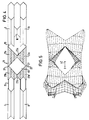
- the coupling structure is essential in connection with the present invention KS (compare Fig. 3 and 4), through which suggestions of the mass of one (upper) transducer 7 strictly in phase opposition to the mass of the other (lower) Schwingers 8 (see Fig. 4) are transmitted and vice versa.
- the Coupling structure KS consists of one in the upper and lower wafer layer Coupling element 21, which in turn consists of two lying in the wafer layer Individual elements 21a, 21b, which have at least one spiral spring 27 are interconnected.
- Fig. 2 shows the middle wafer layer with a frame 2, in which on the right side a fixed one that extends across the frame width Plate drive element 5 is formed, via which when a drive voltage is applied the electrostatic drive takes place due to use of the plate drive element 5 integrally connected to the frame 2 for upper drive plate element 4 or its counterpart on the bottom desired narrow drive gap is set.
- 2 shows that the coupling webs 23a, 23b initially, that is to say before the three wafer layers are bonded, via narrow springs or webs 26a or 26b with the frame 2 are connected. These webs 26a, 26b are like a web 25, the one Intermediate support element 10 initially holds between the upper support 9 and the lower carrier 11 after the bonding is cut or removed.
- Coriolis rotation rate sensors can be at high Vibration quality in spite of deviating oscillator masses or deviating spring constants very good stability of the oscillator amplitudes due to forced Achieve antiphase.
Abstract
Description
Die Erfindung betrifft einen mikromechanischen Drehratensensor basierend auf dem Coriolis-Prinzip. mit zwei jeweils in mindestens einer Waferschicht ausgebildeten und schichtartig übereinander in zwei parallelen Ebenen angeordneten und mittels eines elektrostatischen Antriebs zu Schwingungen senkrecht zu den Ebenen anregbaren plattenförmigen Schwingern.The invention relates to a micromechanical rotation rate sensor based on the Coriolis principle. with two each in at least one wafer layer trained and layered on top of each other in two parallel planes arranged and by means of an electrostatic drive to vibrate plate-shaped transducers that can be excited perpendicular to the planes.
Ein mikromechanischer Drehratensensor mit den im vorstehenden Absatz
angegebenen Merkmalen ist in der internationalen Patentanmeldung WO 96/38710
ausführlich beschrieben; auf diese Druckschrift wird voll inhaltlich Bezug
genommen. Fig. 6 der beigefügten Zeichnungen veranschaulicht diesen Stand
der Technik (vergleiche auch Fig. 9 der genannten WO-Druckschrift). Wie oben
kurz umrissen, umfaßt ein solcher Drehratensensor zwei fluchtend und schichtartig
übereinander angeordnete Schwinger, von denen in der Perspektivdarstellung
der Fig. 6 der obere Schwinger 60 sichtbar ist. Dieser Schwinger 60 und
entsprechend auch ein unterer spiegelsymmetrisch angeordneter und nicht
sichtbarer Schwinger ist (jeweils) über eine erste Feder 70 an einen elektrostatischen
plattenförmigen Antrieb 61 angelenkt, der seinerseits über eine
zweite Feder 69 mit einem plattenförmigen Träger 62, über welchen die
Drehratenauslesung erfolgt. verbunden ist. Die ganze reihenartig verbundene
Anordnung aus Schwinger 60. Antrieb 61 und Träger 62 ist über ein Kreuzfedergelenk
63, 63' in einem Rahmen 68 gehalten. Es ist aus Fig. 6 ersichtlich, daß
jede Schwingeranordnung 60, 61, 62 einschließlich des zugehörigen Rahmens 68
zweilagig, also aus einem Verbundwafer, unter Zwischenschaltung einer nicht
dargestellten dünnen Isolationsschicht, beispiels aus SiO2, hergestellt ist. Der
obere zweilagige Rahmen 68 und der untere zweilagige Rahmen 68' umschließen
also die gesamte aus vier Waferschichten hergestellte Schwingerstruktur, wobei
über äußere, einstückig mit den Rahmen verbundene Anschlüsse 64 bis 67
unterschiedliche Potentiale zuführbar sind. Mit Durchführungen für die elektrostatische
(kapazitive) Anregung, Signalauslesung und Rückstellung (im Falle
eines Closed-Loop-Systems) versehene Deck- und Bodenwafer sind in Fig. 6
nicht gezeigt: es wird insoweit auf Fig. 2 der genannten WO-Druckschrift
verwiesen. Der besondere Vorteil dieser zweilagigen Schwingerstruktur nach Fig.
6 besteht unter anderem darin, daß Störungen der Meßwerte durch Reaktionskräfte
aufgrund von Schwingerbewegungen nicht auftreten, obwohl vergleichsweise
große Schwingungsamplituden des Schwingers 60 bzw. des spiegelbildlich
angeordneten Schwingers (in Fig. 6 nicht sichtbar) mit kleinen Kondensatorantriebsspalten
im Bereich des Antriebs 61 realisierbar sind. Die Drehratenauslesung
erfolgt ebenfalls kapazitiv über (nicht gezeigte) Flächenelektroden auf
der Oberseite des Trägers 62 bzw. auf der Unterseite des spiegelbildlichen (hier
nicht sichtbaren) unteren Trägers 62' mit entsprechenden Gegenelektroden am
(nicht gezeigten) Deck- bzw. Bodenwafer. Das dargestellte Kreuzfedergelenk 63,
63' hat den Vorteil, daß rotatorische, durch Coriolis-Kräfte verursachte Bewegungen
mit daraus folgenden Kapazitätsänderungen gut übertragen, dagegen
horizontale und vertikale Schwingungen in diesem Bereich unterdrückt werden.A micromechanical rotation rate sensor with the features specified in the preceding paragraph is described in detail in international patent application WO 96/38710; full reference is made to this publication. FIG. 6 of the accompanying drawings illustrates this prior art (also compare FIG. 9 of the mentioned WO document). As briefly outlined above, such a rotation rate sensor comprises two aligned and layer-like superimposed oscillators, of which the
Bei dieser bekannten, anhand der Fig. 6 erläuterten Schwingerstruktur ist - wie
erwähnt - die elektrostatische Anregung aufgrund des engen Antriebsspalts im
Bereich des Antriebs 61 trotz erwünschter relativ großer Schwingungsamplituden
erheblich erleichtert und mit vergleichsweise niedrigen Antriebsspannungen
von wenigen Volt realisierbar.In this known vibrator structure explained with reference to FIG. 6, how is
mentioned - the electrostatic excitation due to the narrow drive gap in the
Area of the
Während einfache Schwingersysteme den Nachteil haben, daß die Reaktionskräfte in die Montagefläche des Drehratensensors abgleitet werden, wobei Änderungen in der Steifigkeit Rückwirkungen auf das Meßsystem haben mit der Folge von Nichtwiederholbarkeiten des Nullpunkts und des Skalenfaktors, hat ein auch hier mit der Erfindung zu realisierender Doppelschwinger den Vorteil, daß deren Massen gegeneinanderschwingen und so nach außen keine Reaktionskräfte abgegeben werden. Es hat sich jedoch gezeigt, daß durch Toleranzen bei der Herstellung der Schwingermassen und der verschiedenen Federn die Schwingerfrequenzen mehr oder weniger unterschiedlich sind. Damit entstehen Probleme für die Antriebselektronik dadurch, daß man die Schwinger bei einer Mittenfrequenz betreiben muß, deren Amplituden je nach Schwingergüte sehr viel niedriger liegen und deren Phasen sich nicht eindeutig angeben lassen. Elektronische Lösungen, durch die sich beide Amplituden und die gegenseitigen Phasen erfassen lassen, sind aufwendig und störanfällig.While simple vibration systems have the disadvantage that the reaction forces are slipped into the mounting surface of the rotation rate sensor, whereby Changes in stiffness affect the measuring system with the Consequence of non-repeatability of the zero point and the scale factor a double oscillator which can also be realized with the invention has the advantage that their masses swing against each other and so there are no reactive forces to the outside be delivered. However, it has been shown that by tolerances the manufacture of the transducer masses and the various springs Vibrator frequencies are more or less different. With that arise Problems for the drive electronics in that the vibrators at a Must operate center frequency, the amplitudes depending on the vibration quality very are much lower and their phases cannot be clearly stated. Electronic solutions through which both amplitudes and the mutual Having phases recorded is complex and prone to failure.
Der Erfindung liegt damit die Aufgabe zugrunde, einen mikromechanischen Drehratensensor gemäß der eingangs genannten Gattung so zu verbessern, daß eine streng gegenphasige Bewegung der beiden Schwinger erreicht wird. The invention is therefore based on the object of a micromechanical To improve yaw rate sensor according to the type mentioned at the outset so that a strictly opposite phase movement of the two transducers is achieved.
Die Erfindung ist bei einem mikromechanischen Drehratensensor, wie er einleitend definiert wurde dadurch gekennzeichnet, daß die beiden plattenförmigen Schwinger über jeweils mindestens eine Feder je mit einem in der oder den jeweils gleichen Waferschicht(en) ausgebildeten Koppelelement verbunden sind, wobei die Koppelelemente - bezogen auf eine Mittenebene zwischen den Schwingern - spiegelsymmetrisch zueinander konfiguriert und über einen zwischen den Koppelelementen angeordneten Koppelsteg miteinander zu einer Koppelstruktur für die Schwinger verbunden sind, die so strukturiert ist, daß die dadurch verkoppelten Schwinger nur gegenphasig zu Schwingungen erregbar sind.The invention is in a micromechanical rotation rate sensor as he was initially defined characterized in that the two plate-shaped Transducer via at least one spring each with one in the or the coupling element formed in each case the same wafer layer (s) are, the coupling elements - based on a center plane between the Vibrations - configured mirror-symmetrically to each other and via one arranged between the coupling elements coupling web to one another Coupling structure for the transducer are connected, which is structured so that the vibrators thus coupled can only be excited in opposite phases to vibrations are.
Vorzugsweise besteht jedes Koppelelement aus zwei über mindestens eine Biegefeder miteinander verbundenen Einzelelementen, wobei die beiden so verbundenen Einzelelemente in einer oberen Waferschicht mit dem jeweils spiegelbildlich dazu angeordneten Einzelelement in der unteren Waferschicht über je mindestens einen in einer Waferzwischenschicht ausgebildeten Koppelsteg miteinander verkoppelt sind.Each coupling element preferably consists of two via at least one spiral spring interconnected individual elements, the two so connected individual elements in an upper wafer layer with each Individual element in the lower wafer layer arranged in mirror image via at least one coupling web formed in an intermediate wafer layer are coupled together.
Vorteilhafte Weiterbildungen der besonders für die ätztechnische Strukturierung von Siliciumwafern geeigneten Koppelstruktur gemäß der Erfindung sind in weiteren abhängigen Patentansprüchen definiert.Advantageous further developments that are particularly suitable for etching structuring Coupling structure suitable for silicon wafers according to the invention are further dependent claims defined.
Die Erfindung und vorteilhafte Einzelheiten werden nachfolgend unter Bezug auf ein erprobtes und derzeit bevorzugtes Ausführungsbeispiel der Erfindung anhand der Zeichnung näher erläutert. Es zeigen:
- Fig. 1
- in schematischer Perspektivdarstellung die Strukturierung einer ersten (oberen) Waferschicht einer Schwingeranordnung eines Coriolis-Kreisels zur Drehratenmessung mit erfindungsgemäßen Merkmalen;
- Fig. 2
- eine mittlere, unter der oberen Schwingeranordnung gemäß Fig. 2 angeordnete Waferstruktur (Waferzwischenschicht);
- Fig. 3
- die schematische Perspektivdarstellung einer Schwingeranordnung innerhalb eines nur schematisch angedeuteten Rahmens, jedoch ohne elektrostatischen Antrieb zur besseren Verdeutlichung der wesentlichen Merkmale der Erfindung:
- Fig. 4
- eine schematische Schnittdarstellung durch die Schwingeranordnung gemäß Fig. 3;
- Fig. 5
- eine (überzeichnete) topologische Wiedergabe der räumlichen Verformung einer Koppelstruktur innerhalb der Schwingeranordnung nach Fig. 3 als Ergebnis einer numerischen Schwingungssimulation: und
- Fig. 6
- die bereits erläuterte mikromechanische Drehratenmeßanordnung nach dem Stand der Technik entsprechend der genannten WO-Druckschrift.
- Fig. 1
- in a schematic perspective representation the structuring of a first (upper) wafer layer of an oscillator arrangement of a Coriolis gyro for rotation rate measurement with features according to the invention;
- Fig. 2
- a middle wafer structure (wafer intermediate layer) arranged under the upper oscillator arrangement according to FIG. 2;
- Fig. 3
- the schematic perspective view of an oscillator arrangement within a frame indicated only schematically, but without an electrostatic drive to better illustrate the essential features of the invention:
- Fig. 4
- is a schematic sectional view through the oscillator arrangement according to FIG. 3;
- Fig. 5
- a (exaggerated) topological representation of the spatial deformation of a coupling structure within the oscillator arrangement according to FIG. 3 as a result of a numerical vibration simulation: and
- Fig. 6
- the already explained micromechanical rotation rate measuring arrangement according to the prior art in accordance with the aforementioned WO document.
Die Perspektivdarstellung der Fig. 1 zeigt, hergestellt aus einem einzigen Wafer,
einen Rahmen 1, in dem - von links nach rechts - über ein Federgelenk 12, beispielsweise
ein Kreuzfedergelenk. ein für die Drehratenauslesung dienender
plattenförmiger Träger 9, eine daran über mindestens eine Feder 20 angelenkte
Koppelstruktur KS, die über eine oder mehrere Federn 22 an einen plattenförmigen
Schwinger 7 angelenkt ist, der wiederum über eine Feder, beispielsweise
eine Biegefeder 17 mit einem plattenförmigen Antriebselement 4 verbunden ist,
das seinerseits über eine oder mehrere Biegefedern 19 im Rahmen 1 gehalten
ist. Die Anlenkung des Antriebselements 4 innerhalb des Rahmens kann entweder
- wie dargestellt - seitlich oder stirnseitig erfolgen. Die Federn 12 bzw. 17,
sofern als Dreh- bzw. sich kreuzende Federgelenke gestaltet, haben die bereits
erwähnten Vorteile. Denkbar und verwendbar sind jedoch auch anders gestaltete
Federelemente. Im dargestellten Beispiel ist die Masse des Schwingers 7 etwa im
Flächenschwerpunkt der elektrostatischen Antriebsplatte 4 angelenkt, was bei
der Schwingungsanregung zu vorteilhaften Resonanzbedingungen führt, weil der
Antrieb an einer (eventuellen) Drehbewegung nicht teilnimmt. Eine andere
Anlenkung, beispielsweise bei voller Antriebsplatte 4 an deren Rand, wie im
Stand der Technik bekannt, ist jedoch auch möglich, gegebenenfalls mit
Optimierungsvorteilen hinsichtlich der erforderlichen Antriebsleistung.1 shows the perspective view, produced from a single wafer,
a frame 1, in which - from left to right - via a
Wesentlich im Zusammenhang mit der vorliegenden Erfindung ist die Koppelstruktur
KS (vergleiche Fig. 3 und 4), durch welche Anregungen der Masse des
einen (oberen) Schwingers 7 streng gegenphasig auf die Masse des anderen (unteren)
Schwingers 8 (vergleiche Fig. 4) übertragen werden und vice versa. Die
Koppelstruktur KS besteht in der oberen und unteren Waferschicht aus einem
Koppelelement 21, das seinerseits aus zwei In der Waferschicht liegenden
Einzelelementen 21a, 21b besteht, die über mindestens eine Biegefeder 27
miteinander verbunden sind. Senkrecht zur Schicht des einen (oberen) Wafers
sind die zur Innenseite abgeschrägten Einzelelemente 21a, 21b des
Koppelelements 21 über jeweils in einer mittleren Waferschicht ausgebildete
Koppelstege 23a, 23b mechanisch mit den entsprechenden spiegelbildlich dazu
angeordneten Einzelelementen 22a, 22b des anderen (unteren) Koppelelements
22 verbunden.The coupling structure is essential in connection with the present invention
KS (compare Fig. 3 and 4), through which suggestions of the mass of
one (upper) transducer 7 strictly in phase opposition to the mass of the other (lower)
Schwingers 8 (see Fig. 4) are transmitted and vice versa. The
Coupling structure KS consists of one in the upper and lower wafer
Die Fig. 2 zeigt die mittlere Waferschicht mit einem Rahmen 2, in dem auf der
rechten Seite ein über die Rahmenbreite sich erstreckendes feststehendes
Plattenantriebselement 5 ausgebildet ist, über das bei Anlegen einer Antriebsspannung
der elektrostatische Antrieb erfolgt, wobei aufgrund der Verwendung
des mit dem Rahmen 2 einstückig verbundenen Plattenantriebselements 5 zum
oberen Antriebsplattenelement 4 bzw. zu dessen Pendant auf der Unterseite ein
erwünschter schmalen Antriebsspalt festgelegt ist. Die Fig. 2 läßt erkennen, daß
die Koppelstege 23a, 23b zunächst, also vor dem Verbonden der drei Waferschichten,
über schmale Federn oder Stege 26a bzw. 26b mit dem Rahmen 2
verbunden sind. Diese Stege 26a, 26b werden ebenso wie ein Steg 25, der ein
Zwischenträgerelement 10 zunächst hält, zwischen dem oberen Träger 9 und
dem unteren Träger 11 nach dem Verbonden druchtrennt bzw. entfernt.Fig. 2 shows the middle wafer layer with a frame 2, in which on the
right side a fixed one that extends across the frame width
Die besonderen Vorteile der Erfindung sind die folgenden:The particular advantages of the invention are the following:
Für eine hohe Empfindlichkeit des mikromechanischen Drehratensensors sind
durch die erwünschten sehr engen Antriebsspalte zwischen dem (feststehenden)
Plattenantriebselement 5 in der mittleren Waferschicht und dem oberen beweglichen
Plattenantriebselement 4 bzw. dessen unterem Gegenstück sehr niedrige
Gasdrücke im Inneren der gekapselten Drehratensensoranordnung erforderlich.
Damit sind zwangsläufig hohe Schwingergüten verbunden. Insbesondere bei
hohen Schwingergüten jedoch bereitet eine elektronisch erzwungene Gegentaktschwingung
erhebliche schaltungstechnische Schwierigkeiten und/oder den
Verzicht auf eine für höhere Genauigkeiten erforderliche ausreichende
Schwingeramplitude. Mit der Erfindung wird strenge Gegenphasigkeit der beiden
Schwinger 7, 8 erreicht, bei einer inhärent hohen Schwingungsstabilität.For a high sensitivity of the micromechanical rotation rate sensor
due to the desired very narrow drive gaps between the (fixed)
Für Coriolis-Drehratensensoren gemäß der Erfindung lassen sich bei hoher Schwingergüte trotz abweichender Schwingermassen bzw. abweichender Federkonstanten sehr gute Stabilitäten der Schwingeramplituden durch erzwungene Gegenphasigkeit erreichen.For Coriolis rotation rate sensors according to the invention can be at high Vibration quality in spite of deviating oscillator masses or deviating spring constants very good stability of the oscillator amplitudes due to forced Achieve antiphase.
Claims (4)
Applications Claiming Priority (2)
| Application Number | Priority Date | Filing Date | Title |
|---|---|---|---|
| DE19831594 | 1998-07-14 | ||
| DE19831594A DE19831594C1 (en) | 1998-07-14 | 1998-07-14 | Micromechanical rotation rate sensor with coupling structure |
Publications (3)
| Publication Number | Publication Date |
|---|---|
| EP0973010A2 true EP0973010A2 (en) | 2000-01-19 |
| EP0973010A3 EP0973010A3 (en) | 2001-04-04 |
| EP0973010B1 EP0973010B1 (en) | 2006-08-16 |
Family
ID=7874045
Family Applications (1)
| Application Number | Title | Priority Date | Filing Date |
|---|---|---|---|
| EP99110812A Expired - Lifetime EP0973010B1 (en) | 1998-07-14 | 1999-06-04 | Micromechanical rotation rate sensor with coupling structure |
Country Status (3)
| Country | Link |
|---|---|
| US (1) | US6119517A (en) |
| EP (1) | EP0973010B1 (en) |
| DE (1) | DE19831594C1 (en) |
Cited By (1)
| Publication number | Priority date | Publication date | Assignee | Title |
|---|---|---|---|---|
| WO2019030036A1 (en) * | 2017-08-08 | 2019-02-14 | Robert Bosch Gmbh | Yaw-rate sensor, method for producing a yaw-rate sensor |
Families Citing this family (10)
| Publication number | Priority date | Publication date | Assignee | Title |
|---|---|---|---|---|
| DE19828424C1 (en) * | 1998-06-25 | 1999-12-02 | Litef Gmbh | Micromechanical revolution rate sensor base on the Coriolis principle |
| US6443008B1 (en) * | 2000-02-19 | 2002-09-03 | Robert Bosch Gmbh | Decoupled multi-disk gyroscope |
| EP3019442A4 (en) | 2013-07-08 | 2017-01-25 | Motion Engine Inc. | Mems device and method of manufacturing |
| WO2015042700A1 (en) | 2013-09-24 | 2015-04-02 | Motion Engine Inc. | Mems components and method of wafer-level manufacturing thereof |
| WO2015013828A1 (en) | 2013-08-02 | 2015-02-05 | Motion Engine Inc. | Mems motion sensor and method of manufacturing |
| JP6590812B2 (en) | 2014-01-09 | 2019-10-16 | モーション・エンジン・インコーポレーテッド | Integrated MEMS system |
| WO2015154173A1 (en) | 2014-04-10 | 2015-10-15 | Motion Engine Inc. | Mems pressure sensor |
| US11674803B2 (en) | 2014-06-02 | 2023-06-13 | Motion Engine, Inc. | Multi-mass MEMS motion sensor |
| WO2016090467A1 (en) | 2014-12-09 | 2016-06-16 | Motion Engine Inc. | 3d mems magnetometer and associated methods |
| US10407299B2 (en) | 2015-01-15 | 2019-09-10 | Motion Engine Inc. | 3D MEMS device with hermetic cavity |
Citations (2)
| Publication number | Priority date | Publication date | Assignee | Title |
|---|---|---|---|---|
| WO1996038710A1 (en) * | 1995-05-31 | 1996-12-05 | Litef Gmbh | Micromechanical rotation speed sensor |
| US5763781A (en) * | 1995-02-23 | 1998-06-09 | Netzer; Yishay | Coupled resonator vibratory rate sensor |
Family Cites Families (3)
| Publication number | Priority date | Publication date | Assignee | Title |
|---|---|---|---|---|
| DE4022495A1 (en) * | 1990-07-14 | 1992-01-23 | Bosch Gmbh Robert | MICROMECHANICAL SPEED SENSOR |
| DE4414237A1 (en) * | 1994-04-23 | 1995-10-26 | Bosch Gmbh Robert | Micromechanical vibrator of an oscillation gyrometer |
| DE19528961C2 (en) * | 1995-08-08 | 1998-10-29 | Daimler Benz Ag | Micromechanical rotation rate sensor (DRS) and sensor arrangement |
-
1998
- 1998-07-14 DE DE19831594A patent/DE19831594C1/en not_active Expired - Fee Related
-
1999
- 1999-06-04 EP EP99110812A patent/EP0973010B1/en not_active Expired - Lifetime
- 1999-07-13 US US09/352,258 patent/US6119517A/en not_active Expired - Fee Related
Patent Citations (2)
| Publication number | Priority date | Publication date | Assignee | Title |
|---|---|---|---|---|
| US5763781A (en) * | 1995-02-23 | 1998-06-09 | Netzer; Yishay | Coupled resonator vibratory rate sensor |
| WO1996038710A1 (en) * | 1995-05-31 | 1996-12-05 | Litef Gmbh | Micromechanical rotation speed sensor |
Cited By (2)
| Publication number | Priority date | Publication date | Assignee | Title |
|---|---|---|---|---|
| WO2019030036A1 (en) * | 2017-08-08 | 2019-02-14 | Robert Bosch Gmbh | Yaw-rate sensor, method for producing a yaw-rate sensor |
| US11466985B2 (en) | 2017-08-08 | 2022-10-11 | Robert Bosch Gmbh | Rotation-rate sensor, method for producing a rotation-rate sensor |
Also Published As
| Publication number | Publication date |
|---|---|
| EP0973010A3 (en) | 2001-04-04 |
| US6119517A (en) | 2000-09-19 |
| DE19831594C1 (en) | 2000-01-27 |
| EP0973010B1 (en) | 2006-08-16 |
Similar Documents
| Publication | Publication Date | Title |
|---|---|---|
| EP0828992B1 (en) | Micromechanical rate-of-rotation sensor | |
| EP2208020B1 (en) | Yaw rate sensor | |
| DE19641284C1 (en) | Rotation rate sensor with decoupled orthogonal primary and secondary vibrations | |
| DE19530007C2 (en) | Yaw rate sensor | |
| DE69829022T2 (en) | Biaxial, micro-mechanical rotary sensor system fulfilling navigation requirements | |
| DE19928759B4 (en) | Angular rate sensor | |
| WO1996038710A9 (en) | Micromechanical rotation speed sensor | |
| EP2162702B1 (en) | Coriolis gyro | |
| EP2531813B1 (en) | Coriolis gyroscope having correction units and method for reducing the quadrature bias | |
| DE60032100T2 (en) | Micro gyroscope with two resonant plates | |
| DE3417858A1 (en) | ANGLE SPEED SENSING SYSTEM | |
| EP2160566A1 (en) | Rotation rate sensor | |
| DE19801981C2 (en) | Vibration type angular velocity sensor | |
| EP0775290B1 (en) | Gyrometer | |
| DE10195200B4 (en) | Vibration-type micro-gyroscope with a planar gimbals structure | |
| EP1472506B1 (en) | Micromechanical rotation speed sensor | |
| DE19831594C1 (en) | Micromechanical rotation rate sensor with coupling structure | |
| DE19828424C1 (en) | Micromechanical revolution rate sensor base on the Coriolis principle | |
| EP1309834B1 (en) | Rotation speed sensor and rotation speed sensor system | |
| EP2423654B1 (en) | Micromechanical sensor with bandpass characteristics | |
| DE102005045378A1 (en) | Angular rate sensor for vehicle, has selection oscillator with tines that are arranged at distance and are connected with each other by base, where direct voltage is applied to excitation oscillator that is provided with electrodes | |
| DE3422889A1 (en) | RINGLASER GYROSCOPE | |
| DE102005008352A1 (en) | Rotation rate sensor for determining angular speed, has torsion bar placed on base of excitation oscillator so that it is connected to substrate via fixture |
Legal Events
| Date | Code | Title | Description |
|---|---|---|---|
| PUAI | Public reference made under article 153(3) epc to a published international application that has entered the european phase |
Free format text: ORIGINAL CODE: 0009012 |
|
| AK | Designated contracting states |
Kind code of ref document: A2 Designated state(s): FR GB |
|
| AX | Request for extension of the european patent |
Free format text: AL;LT;LV;MK;RO;SI |
|
| PUAL | Search report despatched |
Free format text: ORIGINAL CODE: 0009013 |
|
| AK | Designated contracting states |
Kind code of ref document: A3 Designated state(s): AT BE CH CY DE DK ES FI FR GB GR IE IT LI LU MC NL PT SE |
|
| AX | Request for extension of the european patent |
Free format text: AL;LT;LV;MK;RO;SI |
|
| 17P | Request for examination filed |
Effective date: 20010529 |
|
| AKX | Designation fees paid |
Free format text: FR GB |
|
| REG | Reference to a national code |
Ref country code: DE Ref legal event code: 8566 |
|
| 17Q | First examination report despatched |
Effective date: 20050316 |
|
| GRAP | Despatch of communication of intention to grant a patent |
Free format text: ORIGINAL CODE: EPIDOSNIGR1 |
|
| GRAS | Grant fee paid |
Free format text: ORIGINAL CODE: EPIDOSNIGR3 |
|
| GRAA | (expected) grant |
Free format text: ORIGINAL CODE: 0009210 |
|
| AK | Designated contracting states |
Kind code of ref document: B1 Designated state(s): FR GB |
|
| REG | Reference to a national code |
Ref country code: GB Ref legal event code: FG4D Free format text: NOT ENGLISH |
|
| GBT | Gb: translation of ep patent filed (gb section 77(6)(a)/1977) |
Effective date: 20060821 |
|
| ET | Fr: translation filed | ||
| PLBE | No opposition filed within time limit |
Free format text: ORIGINAL CODE: 0009261 |
|
| STAA | Information on the status of an ep patent application or granted ep patent |
Free format text: STATUS: NO OPPOSITION FILED WITHIN TIME LIMIT |
|
| 26N | No opposition filed |
Effective date: 20070518 |
|
| PGFP | Annual fee paid to national office [announced via postgrant information from national office to epo] |
Ref country code: FR Payment date: 20080618 Year of fee payment: 10 |
|
| PGFP | Annual fee paid to national office [announced via postgrant information from national office to epo] |
Ref country code: GB Payment date: 20080624 Year of fee payment: 10 |
|
| GBPC | Gb: european patent ceased through non-payment of renewal fee |
Effective date: 20090604 |
|
| REG | Reference to a national code |
Ref country code: FR Ref legal event code: ST Effective date: 20100226 |
|
| PG25 | Lapsed in a contracting state [announced via postgrant information from national office to epo] |
Ref country code: FR Free format text: LAPSE BECAUSE OF NON-PAYMENT OF DUE FEES Effective date: 20090630 |
|
| PG25 | Lapsed in a contracting state [announced via postgrant information from national office to epo] |
Ref country code: GB Free format text: LAPSE BECAUSE OF NON-PAYMENT OF DUE FEES Effective date: 20090604 |