BACKGROUND OF THE INVENTION
Field of the Invention:
The present invention relates to a positioner which can
easily set an output signal such that a controlled object is
set to an arbitrary control condition corresponding to an
input signal and its setting method.
Description of the Related Art:
Positioners have been used for controlling actuators
such as diaphragm motors, cylinders and the like. The
positioner controls a pressurized fluid in response to an
input signal inputted as an electric signal, an air pressure
signal or the like and sets a rotational angle of a rotary
shaft of the diaphragm motor, a displacement position or the
like of a piston of the cylinder to a given angle and
position.
For example, in case the diaphragm motor which is
controlled by this positioner is used for opening or closing
a valve, a flow rate of a fluid which flows through the
valve can be controlled in response to an input signal such
as an electric signal, an air pressure signal or the like
inputted to the positioner.
In the above flow rate control, the rotational angle
of the rotary shaft of the diaphragm motor is not
necessarily proportional to the flow rate of the fluid which
passes through the valve. Conventionally, in setting the
input signal inputted to the positioner and the flow rate of
the fluid which passes through the valve to have a
proportional relation, flow rate characteristics
respectively corresponding to a large number of input
signals are required to be measured and a conversion
relation which makes the flow rate characteristics linear
must be obtained. Accordingly, an operation for setting the
conversion relation is complexed and such a setting
operation takes a considerably long time and pushes up the
cost.
SUMMARY OF THE INVENTION
It is a general object of the present invention to
provide a positioner which can set a conversion relation in
a short time and can reduce the cost needed in setting such
a conversion relation and a method for performing such a
setting.
It is a main object of the present invention to provide
a positioner which can easily set an arbitrary conversion
relation and a method for performing such a setting.
The above and other object, features and advantages of
the present invention will become more apparent from the
following description when taken in conjunction with the
accompanying drawings in which a preferred embodiment of the
present invention is shown by way of illustrative examples.
BRIEF DESCRIPTION OF THE DRAWINGS
FIG. 1 is a partial cross-sectional view of a
positioner according to an embodiment of the present
invention;
FIG. 2 is a longitudinal cross-sectional view of the
positioner shown in FIG. 1;
FIG. 3 is a circuit block diagram of the positioner
shown in FIG. 1;
FIG. 4 is a circuit block diagram showing the relation
among the positioner shown in FIG. 1, a valve connected with
the positioner and a pipeline connected with the valve;
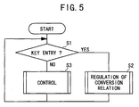
FIG. 5 is a flow chart showing the manner of using the
positioner according to the embodiment of the present
invention;
FIG. 6 is a flow chart of the manner of setting the
positioner according to the embodiment of the present
invention, which shows steps for setting a minimum command
and a maximum command;
FIG. 7 is a flow chart of the manner of setting the
positioner according to the embodiment of the present
invention, which shows steps for setting given commands; and
FIG. 8 is a graph showing the relation among the input
signals inputted in accordance with the method for setting
the positioner according to the embodiment of the present
invention, the commands and the flow rate.
DESCRIPTION OF THE PREFERRED EMBODIMENT
A positioner and its setting method according to the
present invention are explained in detail hereinafter with
reference to a preferred embodiment in conjunction with
attached drawings.
In FIG. 1 and FIG. 2, numeral 10 indicates a positioner
according to this embodiment. The positioner 10 includes a
casing 12 in which a printed board 14 is disposed. A
display unit 16 and a key entry unit 18 which constitutes a
setting unit are mounted on the printed board 14. The key
entry unit 18 is provided with an up key 20a, a down key 20b
and a set key 20c. A feedback shaft 22 is pivotally mounted
on the casing 12. One end of the feed back shaft 22 is
connected to an angle sensor 24. The other end of the feed
back shaft 22 is connected to a rotary shaft 30 of a
diaphragm motor 28 which constitutes a controlled object of
this positioner 10. As shown in FIG. 3, the rotary shaft 30
of a diaphragm motor 28 is connected to a drive shaft 33 of
a valve 32 and a degree of opening of the valve 32 is
regulated by an amount of rotation of the rotary shaft 30.
The casing 12 is provided with a supply passage 34 for
introducing compressed air, inlet and outlet passages 36, 38
which are connected with the diaphragm motor 28. Pressure
gages 40a - 40c are respectively mounted on the supply
passage 34 and the inlet and outlet passages 36, 38. A
cable connector 42 connected to the printed board 14 is
disposed for the casing 12.
Next, the positioner 10 is explained with reference to
the circuit block diagram of FIG. 3.
Input signals a which are indicated as voltage values
or the like are inputted to an input unit 52 of the printed
board 14 of the positioner 10 from an input terminal 50 by
way of the cable connector 42. The input unit 52 includes
an A/D converter , for example, and converts input signals
to digital values and inputs them to a command operation
unit (a signal conversion unit) 54. The display unit 16,
the key entry unit 18 and a memory unit 56 made up of
rewritable RAM and the like are connected to the command
operation unit 54.
A control operation unit (a control unit) 60 is
connected to the command operation unit 54 and outputs of
the control operation unit 60 are inputted to an
electricity-air conversion unit (conversion means) 62. The
electricity-air conversion unit 62 converts the pressure of
the compressed air supplied from a fluid pressure supply
source 64 to a pressure corresponding to outputs of the
control operation unit 60 and outputs it to the diaphragm
motor 28 as an output signal e. The angle sensor 24 which
is connected to the rotary shaft 30 of the diaphragm motor
28 detects the rotational angle of the rotary shaft 30 and
inputs it to the control operation unit 60 as an angle
signal c.
As shown in FIG. 4, a pipeline 66 for fluid is
connected to the valve 32 which is connected to the
positioner 10 and a flowmeter 68 is mounted on the pipeline
66.
The positioner 10 according to this embodiment
basically has the above-mentioned construction. The
operation of the positioner 10 will be explained hereinafter
in connection with the setting method according to this
embodiment.
First of all, in case there is a key entry or key input
for regulating the conversion relation from the input
signals to the command signals from the key entry unit 18
of the positioner 10 (step S1 in FIG. 5), the operation
proceeds to a subroutine for regulating the conversion
relation (step S2). In case there is no key entry or key
input for regulating the conversion relation at the step S1,
the operation proceeds to a subroutine for controlling the
valve 32 as originally expected (step S3).
Here, the subroutine for regulating the conversion
relation is explained with reference to FIG. 6.
The conversion relation of commands (command signals) b
which are angles of the rotary shaft 30 relative to the
input signals a is preliminarily stored in the memory unit
56. In this conversion relation, as shown by a broken line
70 in FIG. 8, the input signals a and the commands b are set
to be in a proportional relation. Here, controlled variable,
namely, the flow rate d of a fluid which flows through the
valve 32 varies corresponding to the commands b so that it
follows a curve 72 shown in FIG. 8.
In the above condition, first of all, a minimum input
signal amin which is the smallest value among the input
signals a is inputted to the input terminal 50 (step S21).
The minimum input signal amin is converted to a digital value
by the input unit 52 and is inputted to the command
operation unit 54. In this command operation unit 54, a
command (the minimum command signal) b which corresponds to
the minimum input signal amin is read out from the memory
unit 56 (see the broken line 70) and the angle of the rotary
shaft 30 of the diaphragm motor 28 is controlled to the
command b (step S22).
To explain this control in detail, the command b is
outputted from the command operation unit 54 to the control
operation unit 60. On the other hand, the angle of the
rotary shaft 30 of the diaphragm motor 28 is converted to an
electric signal by the angle sensor 24 and the electric
signal is inputted to the control operation unit 60 as an
angle signal c.
In this control operation unit 60, the difference
between the command b and the angle signal c is calculated
and a control operation such as a PID control or the like is
implemented on this difference and its result is inputted to
the electricity-air conversion unit 62.
Subsequently, the electricity-air conversion unit 62
controls the pressure of the compressed air supplied from
the fluid pressure supply source 64 based on the above
computed result. This compressed air is outputted to the
diaphragm motor 28 from the input and output passages 36, 38
as an output signal e and the rotary shaft 30 is rotated.
The control of pressure can be performed in such a manner
that a solenoid valve or the like mounted on the positioner
10 (not shown) is controlled so as to change the supply
passage for compressed air to the diaphragm motor 28. In
this manner, the output of the diaphragm motor 28, namely,
the angle of the rotary shaft 30 gradually approaches the
command b and finally agrees with the command b and hence,
the degree of opening of the valve 32 is regulated.
Here, the flow rate d is measured by the flowmeter 68
(step S23). Then, the setting of the minimum command bmin
which can obtain a desired minimum flow rate dmin is
performed at the key entry unit 18 (step S24). In this case,
when the up key 20a is manipulated, the value of the command
b is increased (step S25), while when the down key 20b is
manipulated, the value of the command b is decreased (step
S26). Accordingly, the rotary shaft 30 is rotated
corresponding to the change of the value of the command b
(step S22). Then, when the flow rate d measured by the
flowmeter 68 reaches the desired controlled variable, namely,
the minimum flow rate dmin, by manipulating the set key 20c
the changed command b is stored as the minimum command bmin
in the memory unit 56 (step S27). Here, it is sufficient
for an operator to recognize the relation between the
minimum input signal amin and the minimum flow rate dmin and
it is unnecessary for the operator to know the minimum
command bmin.
Subsequently, a maximum input signal amax which is the
largest value among the input signals a is inputted to the
input terminal 50 (step S28). The maximum input signal amax
is converted to a digital value by the input unit 52 and is
inputted to the command operation unit 54. In this command
operation unit 54, a command (the maximum command signal) b
which corresponds to the maximum input signal amax is read
out from the memory unit 56 (see the broken line 70) and is
outputted to the control operation unit 60. Accordingly,
the rotary shaft 30 of the diaphragm motor 28 is controlled
to the angle corresponding to this command b and the flow
rate d of the fluid which flows through the valve 32 is
changed (step S29). Then, the flow rate d is measured by
the flowmeter 68 (step S30).
Then, the setting of the maximum command bmax which can
obtain a desired maximum flow rate dmax is performed at the
key entry unit 18 (step S31). In this case also, in the
same manner as the steps S25 to S27, when the up key 20a is
manipulated, the value of the command b is increased (step
S32), while when the down key 20b is manipulated, the value
of the command b is decreased (step S33). Accordingly, the
rotary shaft 30 is rotated corresponding to the change of
the value of the command b and the flow rate d flown to the
valve 32 is changed (step S29). Then, when the flow rate d
reaches the desired controlled variable, namely, the maximum
flow rate dmax, by manipulating the set key 20c the changed
command b is stored as the maximum command bmax in the memory
unit 56 (step S34). Here, it is also sufficient for the
operator to recognize the relation between the maximum input
signal amax and the maximum flow rate dmax and it is
unnecessary for the operator to know the maximum command bmax.
After setting the minimum command bmin and the maximum
command bmax in the above manner, the command operation unit
54 computes a conversion relation in which a given command
(given command signal) bn relative to a given input signal
an is arranged on a straight line which connects a cross
point of the minimum input signal amin and the minimum
command bmin and a cross point of the maximum input signal
amax and the maximum command bmax as shown by a broken line 74
in FIG. 8, and such a conversion relation is stored in the
memory unit 56 (step S35 in FIG. 7). In this case, for
example, a plurality of commands b1 to b9 are set
corresponding to a plurality of input signals a1 to a9 which
are equally divided between the minimum input signal amin
and the maximum input signal amax. Here, the value n is 1 to
9 and the maximum value nmax of the value n is set to 9.
Subsequently, the command bn is altered such that the
flow rate d of the fluid becomes proportional to the input
signal a and the conversion relation of the command bn
relative to the input signal a stored in the memory unit 56
is regulated. In this method, first of all, the value of a
register in the command operation unit 54 (not shown) is set
to 1 (step S36). Subsequently, the input signal an which
corresponds to the value of the register, namely, the input
signal a1 in this case, is inputted to the input terminal 50
(step S37). This input signal a1 is converted to a digital
value by the input unit 52 and is inputted to the command
operation unit 54. At the command operation unit 54, the
command bn which corresponds to the input signal an is read
out from the memory unit 56 and is outputted to the control
operation unit 60. Accordingly, the rotary shaft 30 of the
diaphragm motor 28 is controlled to the angle which
corresponds to this command bn (step S38). Then, the flow
rate d of the fluid which flows through the valve 32 is
measured (step S39).
Then, the setting of the command is performed at the
key entry unit 18 (step S40). In this case also, in the
same manner as the steps S25 to S27, when the up key 20a is
manipulated, the value of the command is increased (step
S41), while when the down key 20b is manipulated, the value
of the command is decreased (step S42). Accordingly, the
rotary shaft 30 is rotated corresponding to the change of
the value of the command and the flow rate d of the fluid
which flows through the valve 32 is changed (step S38).
Then, the command b is changed such that the flow rate d
takes the value proportional to the input signal a as shown
in a straight line 76 in FIG. 8 and the set key 20c is
manipulated so as to store this value of the command bn into
the memory unit 56 (step S43).
Subsequently, it is determined whether the value n set
to the register is the value nmax or not (step S44). Since
the value n is not the value nmax in this case, the value of
the register is increased by 1 so that the value n is set to
2 (step S45). Subsequently, the operation returns to the
step S37 and the input signal an which corresponds to the
value n of the register, namely, the input signal a2 in this
case, is inputted to the input terminal 50. Thereafter, the
steps ranging from the step S38 to the step S45 are repeated
and the value of the altered command bn, namely the value of
the command b2 in this case, is stored in the memory unit 56.
In the same manner, the value n of the register is
increased in sequence and the values of the commands bn
corresponding to respective values n of the register are
stored in the memory unit 56.
The command bn is determined in the above manner and
when the value n of the register becomes nmax in the step S44,
the operation returns to the step S1 in FIG. 5. As
mentioned previously, in case there is no key entry or key
input for regulating the conversion relation, the operation
proceeds to the control subroutine so as to control the
diaphragm motor 28 (step S3).
The conversion relation of the command b relative to
the input signal a which is determined in the above-mentioned
manner takes a curve as shown by the curve 78 in
FIG. 8, while in this case, the input signal a and the flow
rate d are in a proportional relation as shown by the
straight line 76. Furthermore, it is sufficient for the
operator to recognize the input signal a and the desired
flow rate d, while it is unnecessary for the operator to
know the command b, namely, the relation between the angle
of the rotary shaft 30 and the flow rate d (the curve 72).
Still furthermore, the relation of the flow rate d of the
fluid relative to the input signal a set in the above manner
is not limited to the proportional relation and includes a
non-linear relation if necessary.
As explained above, according to the embodiment, it is
unnecessary to preliminarily measure the flow rate d of the
fluid relative to the angle of the rotary shaft 30 of the
diaphragm motor 28 so that the characteristics of the flow
rate d relative to the input signal a can be readily set.