EP0972208B1 - Magnetometer with coil and high permeability core - Google Patents
Magnetometer with coil and high permeability core Download PDFInfo
- Publication number
- EP0972208B1 EP0972208B1 EP98917978A EP98917978A EP0972208B1 EP 0972208 B1 EP0972208 B1 EP 0972208B1 EP 98917978 A EP98917978 A EP 98917978A EP 98917978 A EP98917978 A EP 98917978A EP 0972208 B1 EP0972208 B1 EP 0972208B1
- Authority
- EP
- European Patent Office
- Prior art keywords
- core
- sensor
- voltage
- magnetic field
- circuit
- Prior art date
- Legal status (The legal status is an assumption and is not a legal conclusion. Google has not performed a legal analysis and makes no representation as to the accuracy of the status listed.)
- Expired - Lifetime
Links
- 230000035699 permeability Effects 0.000 title description 16
- 238000004804 winding Methods 0.000 claims description 24
- 239000000463 material Substances 0.000 claims description 19
- 238000000034 method Methods 0.000 claims description 13
- 238000012545 processing Methods 0.000 claims description 6
- 238000010304 firing Methods 0.000 claims 1
- 239000011162 core material Substances 0.000 description 37
- 238000010586 diagram Methods 0.000 description 9
- 229910000697 metglas Inorganic materials 0.000 description 9
- 238000005259 measurement Methods 0.000 description 7
- 230000008859 change Effects 0.000 description 5
- 230000000694 effects Effects 0.000 description 5
- 230000001939 inductive effect Effects 0.000 description 5
- 238000005070 sampling Methods 0.000 description 5
- RYGMFSIKBFXOCR-UHFFFAOYSA-N Copper Chemical compound [Cu] RYGMFSIKBFXOCR-UHFFFAOYSA-N 0.000 description 4
- 239000003990 capacitor Substances 0.000 description 4
- 230000035945 sensitivity Effects 0.000 description 4
- 230000008901 benefit Effects 0.000 description 3
- 238000001514 detection method Methods 0.000 description 3
- 238000012886 linear function Methods 0.000 description 3
- 230000007704 transition Effects 0.000 description 3
- 230000005330 Barkhausen effect Effects 0.000 description 2
- 241000272184 Falconiformes Species 0.000 description 2
- XEEYBQQBJWHFJM-UHFFFAOYSA-N Iron Chemical compound [Fe] XEEYBQQBJWHFJM-UHFFFAOYSA-N 0.000 description 2
- 230000004075 alteration Effects 0.000 description 2
- 238000013459 approach Methods 0.000 description 2
- 229910052802 copper Inorganic materials 0.000 description 2
- 239000010949 copper Substances 0.000 description 2
- 238000005516 engineering process Methods 0.000 description 2
- 238000004519 manufacturing process Methods 0.000 description 2
- 239000000126 substance Substances 0.000 description 2
- 238000004458 analytical method Methods 0.000 description 1
- 238000004364 calculation method Methods 0.000 description 1
- 238000006243 chemical reaction Methods 0.000 description 1
- 230000000295 complement effect Effects 0.000 description 1
- 230000007547 defect Effects 0.000 description 1
- 230000003111 delayed effect Effects 0.000 description 1
- 230000005347 demagnetization Effects 0.000 description 1
- 230000001419 dependent effect Effects 0.000 description 1
- 238000009795 derivation Methods 0.000 description 1
- 238000011161 development Methods 0.000 description 1
- 230000009977 dual effect Effects 0.000 description 1
- 230000005611 electricity Effects 0.000 description 1
- 230000005284 excitation Effects 0.000 description 1
- 230000001747 exhibiting effect Effects 0.000 description 1
- 238000002474 experimental method Methods 0.000 description 1
- 230000010354 integration Effects 0.000 description 1
- 229910052742 iron Inorganic materials 0.000 description 1
- 230000005381 magnetic domain Effects 0.000 description 1
- 230000005389 magnetism Effects 0.000 description 1
- 238000005404 magnetometry Methods 0.000 description 1
- 230000010355 oscillation Effects 0.000 description 1
- 230000004044 response Effects 0.000 description 1
- 230000000630 rising effect Effects 0.000 description 1
- 239000004065 semiconductor Substances 0.000 description 1
- 230000001960 triggered effect Effects 0.000 description 1
Images


Classifications
-
- G—PHYSICS
- G01—MEASURING; TESTING
- G01C—MEASURING DISTANCES, LEVELS OR BEARINGS; SURVEYING; NAVIGATION; GYROSCOPIC INSTRUMENTS; PHOTOGRAMMETRY OR VIDEOGRAMMETRY
- G01C17/00—Compasses; Devices for ascertaining true or magnetic north for navigation or surveying purposes
- G01C17/02—Magnetic compasses
- G01C17/28—Electromagnetic compasses
- G01C17/30—Earth-inductor compasses
-
- G—PHYSICS
- G01—MEASURING; TESTING
- G01R—MEASURING ELECTRIC VARIABLES; MEASURING MAGNETIC VARIABLES
- G01R33/00—Arrangements or instruments for measuring magnetic variables
- G01R33/02—Measuring direction or magnitude of magnetic fields or magnetic flux
Definitions
- the present invention is in the area of apparatus and methods for measuring and quantifying magnetic fields, and pertains in preferred embodiments to a weak-field magnetometer useful for navigation instruments such as digitized compasses and the like.
- a variety of magnetometers for weak field detection are known in the art.
- One such is taught in U.S. Patent No. 4,314,200 to Hawks et al or No. 4,581,775 by Kim et al.
- the Kim magnetometer is an oscillator whose frequency of oscillation changes as a function of applied magnetic field, and because of this the sampling rate is limited for fast moving magnetic fields.
- the Kim magnetometer in order to obtain adequate resolution for measuring frequency shifts of an oscillating signal centered around, for example, 50 kHz, one must count up to 300 cycles of the signal waveform against a 5MHz gating clock in order to obtain 150 nT field resolutions. This limits the ability to sample field changes to only about a 50Hz rate.
- the sensor circuit becomes an inherent low-pass filter. Although this limitation might be desirable for rejecting unwanted high frequency noise components, such as 60Hz powerline noise, there is no good technique which can be used with this frequency detection scheme to purposely measure higher frequency events.
- the frequency approach in magnetometer technology is also inherently noisy, as a slow comparator is required in order to reject spurious noise from sources such as a microprocessor clock on a power supply in a digitized system. Since a slow comparator moves slowly through the transition range, it is susceptible to frequency modulation (FM) caused by what is known in the art as the Barkhausen effect. This in tun creates noise. This FM limits the bottom of the noise floor to about 15nT. Power consumption also is relatively high for frequency-based magnetometer systems since such systems must operate on both halves of each oscillator cycle.
- FM frequency modulation
- each positive-going cycle must charge up to the positive hysteresis point of a Schmitt trigger as set by a feedback resistor, while each negative cycle must charge down to the negative hysteresis point as well.
- the area under the curve is integrated, it can be seen that more power is expended than if only one half of a cycle were used.
- the Hawks magnetometer there is a Capacitor C and dual switches S1 and S2.
- the capacitor C is switched into the circuit and charges the circuit up to a pre-selected voltage and current with the capacitor, and then measures the time required, after disconnecting the capacitor for the voltage to decay to a second point. After the cycle is initiated, a first time is required for the voltage to go from 0 to V H , and a second time is measured t(H E ), for the voltage to then drop to V L .
- time measurement begins during the portion of operation that would be the "charge-up" and, therefore, the instrument always operates in one or the other of a charge-up or decay mode (depending on where in the circuit the effects are measured, but not in both.
- a sensor for quantifying magnetic field strength comprising a core of elongated high-magnetic-permeability material having a central long axis; and a multi-turn winding of electrically conducting wire wound on the core along the long axis of the core, and electrically insulated from the core.
- the sensor in one embodiment further comprises an electrically-insulating, elongated bobbin element having a hollow central axis, wherein the multi-turn winding is wound on the outside of the bobbin and the core is positioned along the hollow central axis of the bobbin.
- Mctglas material is one suitable choice for the core material, and the winding may be provided on the core using a single length of lacquered copper wire having a first end at one end of the bobbin and a second end at the opposite end of the bobbin.
- the senor is utilized in a magnetometer comprising a driver circuit having a voltage-controlled output; a sensor comprising a core of elongated high-magnetic-permeability material having a central long axis and a multi-turn winding of electrically conducting wire wound on the core along the long axis of the core, and electrically insulated from the core, the sensor connected by a first end of the winding to the voltage controlled output of the driver circuit; and a measuring circuit connected to a second end of the winding and adapted to measure time for voltage at the second end to reach a pre-selected reference voltage.
- the driver circuit may have a reset and a comparator may be used to reset the driver when voltage at an output of the sensor reaches a reference voltage, providing thereby an output having a train of pulses having a pulse width proportional to the strength of any magnetic field in the direction of the long axis of the sensor element.
- a navigation instrument comprising three sensing units, each sensing unit comprising a sensor for quantifying magnetic field strength, the sensor comprising a core of elongated high-magnetic-permeability material having a central long axis, and a multi-turn winding of electrically conducting wire wound on the core along the long axis of the core, and electrically insulated from the core; three driver circuits each having a voltage-controlled output and connected one each to a first end of the multi-turn winding of one of the sensors; and a measuring circuit connected to a second end of each of the multi-turn windings and adapted to measure time for voltage at the second end of each of the windings to reach a pre-selected reference voltage.
- the central long axes of the cores of the three sensors are arranged mutually orthogonally. In other embodiments there may be two sensor units at right angles for those situations where measurements in two dimensions will suffice.
- the navigation instrument described above further comprises processing and display circuitry coupled to the measuring circuitry, and adapted for processing measurement data reported by the measuring circuitry and displaying processed data to a user.
- the navigational instrument can be a digital compass, wherein the processed data displayed indicates direction.
- a digital compass comprising multiple sensing units, each sensing unit comprising a sensor for quantifying magnetic field strength, the sensor comprising a core of elongated high-magnetic-permeability material having a central long axis, and a multi-turn winding of electrically conducting wire wound on the core along the long axis of the core, and electrically insulated from the core; multiple driver circuits each having a voltage-controlled output and connected one each to a first end of the multi-turn winding of one of the sensors; and a measuring circuit connected to a second end of each of the multi-turn windings and adapted to measure time for voltage at the second end of each of the windings to reach a pre-selected reference voltage.
- the central long axes of the cores of the three sensors are arranged in different directions. In other embodiments there may be sensors on two axes rather than three.
- the present invention in its several aspects is based on a novel high-sensitivity, weak-field magnetometer device using an inductive sensor element whose reactance is effected by an applied magnetic field and causes a variable output delay to any given input driving signal.
- this feature enables a methodology wherein timed input pulses cause output pulses whose width, and not frequency or duty cycle, varies monotonically in proportion to any given magnetic field applied externally along the sensitive axis of the sensor element.
- Such pulses, whose width varies can be easily measured in many different ways known to those skilled in the art, such as by pulse width detection or integration by a simple capacitive integrator.
- the measurement of output pulse width, properly calibrated may be converted to a direct current analog voltage level which can be subsequently converted into a digital input for use by a processing circuit.
- a field measuring device as described above can be used in a broad variety of applications, such as Earth field sensing for the purpose of providing heading information for a digital compass or for the purpose of linear or angular position or rate sensing either by proximity or encoder sensing as well as many other traditionally difficult and costly uses for measuring weak DC magnetic fields.
- Fig. 1 is an isometric view of an inductive sensor element 11 according to an embodiment of the present invention, useful in circuitry for measuring magnetic fields.
- Sensor element 11 comprises a plastic bobbin 13 of length L1 and diameter D1 having a winding of N1 turns of electrically conductive wire 15.
- An elongated core 17 of high-direct-current-permeability material is arranged along the central axis of bobbin 13.
- voltage across the coil is monitored by connection to the ends of coil wire 15, and variations in voltage are processed as an indication of the strength of any magnetic field in the direction of the axis of bobbin 13.
- High-permeability core 17 in this embodiment is a strip of No. 2705M Metglas® made by Allied Signal Corporation fashioned to dimensions of about 0.60 inches in length by about 0.35 inches width by about .001 inches thickness.
- the wire in this embodiment is 41 gauge lacquer-insulated copper magnet wire, wrapped to 1400 turns on the plastic bobbin. It will be apparent to those with skill in the art that these dimensions and materials are convenient and not necessarily limiting to the invention. There are many other materials and geometries that may be used within the scope of the invention.
- Fig. 2 is a simplified electrical diagram illustrating a use of the sensing coil with other elements to measure magnetic field strength.
- a voltage source 19 a switch 21, a current source 23, and sensor 11 are wired in series and in a loop. That is, one side of the sensor element is connected to one side of the voltage source, and the other side of the sensor element is wired in series through the current source and the switch back to the opposite side of the voltage source.
- closing switch 21 supplies a step function to sensor 11.
- the circuit because of the reactance of sensor 11, appears to be an open circuit, and essentially the full voltage of the voltage source appears across sensor element 11.
- the apparent resistance of the sensor element diminishes, until, at steady state, the sensor appears as a short circuit, displaying very small voltage drop across the sensor, due to the inherent, steady state resistance of the winding wire over the length of the wire forming the winding on the bobbin.
- the nature of the sensor element is such that the time constant for voltage decay across the sensor element is a function of the strength of any magnetic field along the length of the sensor element.
- a resistor may be placed in series with the sensor element, and the voltage across the resistor is measured instead of the voltage across the sensor element.
- the voltage variation is from zero at the instant the switch is closed, and the voltage rises until the full voltage appears across the resistor at the time that the voltage drop across the sensor element reaches zero.
- the time constant for voltage increase across the resistor in this alternative is a monotonic function of the strength of any magnetic field along the long axis of the sensor element.
- a sudden step function is only one way a signal can be provided to the circuit of Fig. 2.
- the step is repeated periodically, so the input is substantially a square waveform, but essentially any other sort of waveform may be used.
- Fig. 3 is a typical permeability curve for a high-permeability material such as the Metglas® material used in embodiment of the invention herein described. Because the permeability of the Metglas® core material is a monotonic function of an applied magnetic field H, the inductance of the sensor is directly proportional to the externally applied magnetic field.
- Fig. 4 is a simple graph illustrating instantaneous current in the circuit of Fig. 2 as a result of closing switch 21.
- step function current Fig. 3
- V ref arbitrary reference voltage
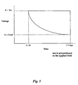
- the time tau shown in Fig. 5 will differ with different values of time constant according to different values of magnetic field strength H along the axis of the sensor coil.
- the difference in time interval for this measurable voltage change is temperature stable, and varies proportionally to the applied magnetic field.
- the time constant of the inductive sensor element is a linear function of II , which is the externally applied magnetic field to be measured. So as stated previously, the time it takes to reach any given reference voltage across the sensor or resistor is a linear function of the applied magnetic field we are trying to measure and is temperature stable.
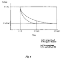
- Fig. 6 is a graph similar to that of Fig. 5, but exhibiting voltage decay across a sensor element under conditions of two different applied fields of strength H1 and H2. Under the influence of the field of strength H1 the time to reach the reference voltage is tau1, and under the influence of the field of strength H2 the time to reach the reference voltage is tau2.
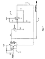
- Fig. 7 is a generalized electrical diagram of an embodiment of the present invention wherein a triggered flip-flop circuit 25 drives a sensor 11 with a repeating square wave of magnitude V cc .
- Vcc is output to Q (pin 5).
- the voltage initially appearing across sensor 11 decays, the voltage at point 27 on the far side of sensor element 11 from Q will rise from ground potential toward V cc as a result of resistor R2.
- a comparator 29 having a preset trip point value is provided connected by pin 2 to point 27. Once the voltage at point 27 (at pin 2 of the comparator) reaches the pre-set trip point value, the comparator will fire low, which, by virtue of line 31 will clear the D flip-flop and cause the output Q to go low.
- the period of the input trigger function is deliberately selected to be longer than any expected time for voltage at pin 2 of the comparator to reach the reference voltage for the highest value of field strength H expected to be measured. Because the comparator fires each time the voltage at pin 2 reaches a pre-set trip value, resetting the flip-flop, and because this time will be less than the period of the input trigger function, the output at Q will be a square wave of magnitude Vcc wherein the pulse width is determined by the strength of any magnetic field along the axis of sensor element 11. This output pulse train appears on line 23, and may be connected to suitable circuitry for measuring the pulse width as a function of the magnetic field strength.
- An advantage of this particular circuit is that it can be gated once for one output pulse, or as many times as is necessary for adequate resolution to be obtained. If the circuit is gated with a clock signal, it will output a train of pulses where each pulse width is determined by the strength of an externally applied magnetic field. It can, of course, be gated with a clock whose frequency is as fast or as slow as desired thereby obtaining high sampling rates with a fast clock, or for saving power and obtaining high resolution with fewer pulses with a slow gating clock.
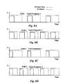
- Figs. 8A through 8D illustrate several output pulse trains produced as a result of input trains of two different gating clock frequencies and for two different values of magnetic field to be measured.
- the external magnetic field strength H1 is common for Fig. 8A and Fig. 8B, but the driving signal clock frequency 1 for Fig. 8A is slower than clock frequency 2 for Fig. 8B.
- the result is that the output pulse is of constant width, independent of clock frequency.
- Fig. 8C and Fig. 8D repeat this illustration for a different magnetic field strength but the same clock frequencies used for Figs. 8A and 8B. It is only necessary that the input pulse width be longer than the output pulse width, which is a simple matter to preset by calculation, and to adjust empirically if necessary.
- the output pulse train on line 23 of Fig. 7, for example, can be fed into a simple voltage integrator to produce a fast-moving DC voltage signal which will be proportional to the applied magnetic field, providing highly accurate, low-noise magnetic field measurements.
- the pulse width can be measured directly with any variety of counting and timing schemes for use by a microprocessor without necessitating any analog to digital conversion.
- the gated clocking is especially useful, since a trip level on the pulse width can be set and a reference one-shot can be generated by the clock signal and fed into an AND gate for high speed determination as to whether a variable field being measured has reached a certain threshold value.
- the AND gate When a preset magnetic field strength threshold has been reached, the AND gate will output a stream of pulses for as long as the magnetic field strength stays above the threshold level. Conversely the AND gate will output nothing when the magnetic field is below the threshold.
- Circuits to accomplish the purposes described herein using the output pulse train from the apparatus with a unique sensor according to an embodiment of this invention may be provided by skilled persons from known circuitry of the sort, without undue experimentation, and are therefore not presented here in detail.
- a very advantageous feature of the new technology taught herein is that the sensor geometry can be provided to complement specific circuit parameters, thereby customizing a magnetometer for optimal performance for any particular magnetic sensing application.
- Another advantage is that the noise floor is extremely low. This is because the magnetometer always operates in one or the other of either a chargeup or in a decay mode, and is not a mix of the two. This, in effect, minimizes the contribution of noise from the well-known Barkhausen effect as the transition of the core material through the permeability curve is always in one direction and is always done in a consistent manner during any one period of the signal and clocking pulse.
- the technique taught herein also minimizes noise caused by any residual hysteresis which the high permeability material might exhibit, thereby eliminating any ambiguity which is caused by the effect of retentivity which manifests itself in the B versus H curve of the core material, causing the classical looping curve path during the demagnetization of the material by the method of reversals [pp 242, Fundamentals of Electricity and Magnetism, Loeb, by John Wiley and Sons, 3rd Edition]. Additionally, a fast comparator can be used without injecting noise, since the sole function of the comparator is that of a voltage level detector. This allows quick transition and substantially reduced FM noise from any ambiguity caused by the hysteresis voltage levels of a Schmitt trigger.
- Metglas® is also a function of frequency. Since some prior art devices change frequency for different applied magnetic field strength, the permeability of a sensor is changing as a direct result of the frequency shift alone.
- the invention described here has the advantage of always operating at a fixed frequency dependent upon the clocking signal, which in practical application will always remain fixed
- the noise floor of the system in an embodiment of the present invention has been measured at well below 1 nanoTesla, and may with further development possibly be in the 1 picoTesla range.
- the sensitivity of the device has been observed to match that of laboratory-grade reference magnetometers, but implemented with less than one dollar's worth of components.
- the material property of the high permeability Metglas® material or any equivalent substance which is key to enabling this invention to work as described. Without the high permeabilities of the Metglas® materials, the change in pulse widths would not be present or measurable, as the weak Earth field and other fields like it would not be able to cause any Barkhausen alignment of the magnetic domains of those other core substances such as iron. Additionally, low-hysteresis exhibited by the Metglas materials also allows the invention to operate within the linear regions of the permeability curve and does not necessitate the operation of the device by driving the core into saturation in order to circumvent the wandering effect caused by retentivity. This is the case with almost all of the magnetometer inventions based on saturable core devices which preceed this present invention.
- the step function driving signal which was described earlier, contains a natural DC bias which biases the operating point of the sensor core material to the desired operating region on its permeability curve.
- This not only provides for optimal operating sensitivity, but it can also be seen that by structuring the electronics to electrically reverse the sensor coil within the circuit, that a forward and a reverse reading can be obtained, which if subtracted from each other will provide a reading value which will be independent of drifts due to temperature, age, or manufacturing defects of the sensors.
- the inventors use an operating circuit topology which is a cycle by cycle differencing integrator, which puts out a zero drift-corrected DC voltage for input into a volt meter or an analog to digital converter. This differencing integrator actually does the forward and backward biasing and sums up the voltage difference between the two and contributes that value to the integrated DC voltage.
- Another extremely advantageous feature in embodiments of the present invention is that there is no perceptible drift in the operation of the sensor due to temperature.
- the only circuit parameter which changes with temperature in a significant fashion for temperatures less than the Curie point is the series resistance of the copper wire used in the windings.
- the time constant change due to this circumstance remains constant, because as the resistance in the wire moves up or down, the inductance of the coil also moves up or down in a manner which tracks the resistance change. This keeps the overall time constant at the same value for a given magnetic field. Since the input of the excitation signal is a step function at the rail value for the comparator, the DC bias component to the sensor core is constant over temperature and does not drift, unlike other biasing schemes used in other prior art magnetometer circuits. This creates a temperature-stable magnetometer.
- the magnetometer is constructed of the following: 1) a plastic bobbin with diameter of 0.15 inches and overall length of 0.8 inches, 2) a Metglas® core of Allied Signal Corp. 2705M cut to the dimensions of 0.600 x 0.35 x 0.001 inches and placed in the center of the bobbin of item 1 above; 3) 1400 turns of 41 guage lacquer-insulated copper magnet wire available from which is almost layer wound onto the bobbin of item 1 above with the core of item 2 above in the center of the unit.
- D-Flip Flop 25 in this embodiment is an AC74 available from many manufacturers, such as National Semiconductor Corp.
- the analog comparator can be any comparator, but the one used for this example is a model TLC3702 from Texas Instruments. Vcc can be almost any voltage, though a nominal voltage of 3 volts has been used preferentially in experiments connected with the present invention.
- Pulldown resistor R 6 in input to the D Flip-Flop is nominally 100k ⁇ , although the specific value will not seriously effect the operation of the device.
- the series resistors R1 and R2 to the sensor coil are chosen to bias the sensor to the desired area of operation on the permeability curve and in this example are 330 ohms each.
- the comparator reference voltage biasing resistors R3 , R4, and R5 are 68k ⁇ (R3), 10k ⁇ (R4) and 22k ⁇ (R5).
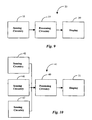
- Fig. 9 is a block diagram illustrating elements in an instrument utilizing a sensing circuit 33 according to an embodiment of the present invention.
- Sensing circuit 33 may be of the architecture of that circuit shown in Fig. 7, or some elements for driving and measuring the sensor element may be different but drawn from circuitry known in the art.
- delayed output of input to sensing circuitry 35 is received by processing circuitry 37, processed to yield field information, and the field information is further processed to be displayed on a display 39.
- Instruments of this sort utilizing single sensing elements may be used for applications wherein field direction is known and field strength measurement is needed.
- Fig. 10 is a block diagram of an instrument 41 utilizing sensing circuitry 43, 45, and 47 according to an embodiment of the present invention, wherein multiple sensors are arranged with axes in different directions to provide data relative to field direction as well as field strength.
- sensors may be arranged mutually orthogonally (X, Y, Z) and suitable algorithms employed by processing circuitry 49 providing display data to a display apparatus 51.
- This architecture may be utilized for a digital compass, for example.
- the sensor is sensitive to the component of any applied field which lies along the long axis of the sensor, two different sensors at different angles can determine field direction in a plane, and three different sensors physically arranged mutually at known angles (right angles for Cartesian analysis) to one another and connected to suitable circuitry may measure both the strength and three-dimensional direction of an applied magnetic field.
- the polarity of a field may be similarly determined.
Landscapes
- Physics & Mathematics (AREA)
- General Physics & Mathematics (AREA)
- Engineering & Computer Science (AREA)
- Radar, Positioning & Navigation (AREA)
- Remote Sensing (AREA)
- Condensed Matter Physics & Semiconductors (AREA)
- Life Sciences & Earth Sciences (AREA)
- Environmental & Geological Engineering (AREA)
- General Life Sciences & Earth Sciences (AREA)
- Geology (AREA)
- Electromagnetism (AREA)
- Measuring Magnetic Variables (AREA)
Description
Power consumption also is relatively high for frequency-based magnetometer systems since such systems must operate on both halves of each oscillator cycle. Typically, in instruments employing this technique, each positive-going cycle must charge up to the positive hysteresis point of a Schmitt trigger as set by a feedback resistor, while each negative cycle must charge down to the negative hysteresis point as well. When the area under the curve is integrated, it can be seen that more power is expended than if only one half of a cycle were used.
In a preferred embodiment a sensor for quantifying magnetic field strength is provided, comprising a core of elongated high-magnetic-permeability material having a central long axis; and a multi-turn winding of electrically conducting wire wound on the core along the long axis of the core, and electrically insulated from the core. The sensor in one embodiment further comprises an electrically-insulating, elongated bobbin element having a hollow central axis, wherein the multi-turn winding is wound on the outside of the bobbin and the core is positioned along the hollow central axis of the bobbin. Mctglas material is one suitable choice for the core material, and the winding may be provided on the core using a single length of lacquered copper wire having a first end at one end of the bobbin and a second end at the opposite end of the bobbin.
three driver circuits each having a voltage-controlled output and connected one each to a first end of the multi-turn winding of one of the sensors; and a measuring circuit connected to a second end of each of the multi-turn windings and adapted to measure time for voltage at the second end of each of the windings to reach a pre-selected reference voltage. In this instrument the central long axes of the cores of the three sensors are arranged mutually orthogonally. In other embodiments there may be two sensor units at right angles for those situations where measurements in two dimensions will suffice.
The voltage across the sensor coil in the circuit of Fig. 2 may be expressed mathematically as follows:

for small changes in field, L = µ 0 n 2 V( dB / dH)
where µ0 is the permeability of free space, n is the number of turns of the sensor, V is the volume of the core material, and dB / bH is the slope of the B versus H curve at any particular point.
Substituting µ(H) = dB / dH
then L = µ 0 n 2 Vµ(H)
Referring to the µ(H) versus H curve of Figure 3, along the linear portions of the right or left half of the curve µ(H) = kH. In other words, µ(H) is a linear function of H and k is the slope of that part of the curve.
So, along these linear portions of the curve of Fig. 3 the time constant is
Claims (8)
- A magnetometer comprising:characterized in that the driver circuit (25) provides a voltage to the sensor (11) and the comparator output fires, resetting the driver circuit (25), when the voltage at the comparator input equals the reference voltage, creating an output train of pulses, and the measuring circuit determines the vector component of a local magnetic field in the direction of the central long axis of the core as a function of the pulse width of the output train of pulses.a driver circuit (25) having a voltage-controlled output and a reset;a sensor (11) comprising a core (17) of elongated high-magnetic-permeability material having a central long axis and a multi-turn winding (15) of electrically conducting wire wound on the core (17) along the long axis of the core (17), and electrically insulated from the core (17), the sensor connected by a first end of the winding (15) to the voltage controlled output of the driver circuit;a measuring circuit connected to the sensor (11);a comparator circuit (29) having a voltage reference, an input connected to a second one end of the winding (15) and an output connected to the reset of the driver circuit (25);
- The magnetometer of claim 1 comprising two or more sensors (11) having long axes disposed in different directions, wherein the measuring circuitry determines the strength and direction of the local magnetic field based on the vector components determined from the sensors (11).
- The magnetometer of claim 1 or 2 further comprising processing and display apparatus disposed to provide a navigation instrument.
- The magnetometer of claim 3 wherein the display (39) provides direction as a compass display.
- A method for determining a component of a local magnetic field, comprising steps of:(a) immersing a sensor (11) in the local magnetic field, the sensor comprising a core (17) of elongated high-magnetic-permeability material having a central long axis and a multi-turn winding (15) of electrically conducting wire wound on the core (17) along the long axis of the core (17), and electrically insulated from the core (17),(b) connecting the sensor (11) by a first end of the winding (15) to a voltage-controlled output of a driver circuit (25) having a reset;(c) connecting a measuring circuit to the sensor (11);(d) connecting a comparator circuit (29) having a voltage reference, and an input connected to a second end of the winding (15), the comparator circuit (29) having an output connected to the reset of the driver circuit (25); and characterized by(e) determining the vector component of the local magnetic field in the direction of the long axis of the core by measuring pulse width of an output train of pulses produced by repeated resetting of the driver (25) as a result of repeated firing by the comparator circuit (29).
- The method of claim 5 wherein step (a) comprises immersing two or more sensors (11) in the local magnetic field, the sensors having long axes disposed in different direction and wherein in step (e) the measuring circuitry determines the strength and direction of the local magnetic field based on the vector components determined from the sensors (11).
- The method of claims 5 or 6 wherein the determined strength and direction of the local magnetic field is used in a navigation instrument.
- The method of claim 7 comprising a step for displaying direction as a compass display.
Applications Claiming Priority (3)
| Application Number | Priority Date | Filing Date | Title |
|---|---|---|---|
| US08/831,322 US6084406A (en) | 1997-04-01 | 1997-04-01 | Half-cycle saturable-core magnetometer circuit |
| US831322 | 1997-04-01 | ||
| PCT/US1998/006451 WO1998044358A1 (en) | 1997-04-01 | 1998-04-01 | Magnetometer with coil and high permeabiliy core |
Publications (3)
| Publication Number | Publication Date |
|---|---|
| EP0972208A1 EP0972208A1 (en) | 2000-01-19 |
| EP0972208A4 EP0972208A4 (en) | 2002-01-30 |
| EP0972208B1 true EP0972208B1 (en) | 2005-11-23 |
Family
ID=25258793
Family Applications (1)
| Application Number | Title | Priority Date | Filing Date |
|---|---|---|---|
| EP98917978A Expired - Lifetime EP0972208B1 (en) | 1997-04-01 | 1998-04-01 | Magnetometer with coil and high permeability core |
Country Status (5)
| Country | Link |
|---|---|
| US (1) | US6084406A (en) |
| EP (1) | EP0972208B1 (en) |
| JP (1) | JP3293835B2 (en) |
| DE (1) | DE69832475T2 (en) |
| WO (1) | WO1998044358A1 (en) |
Families Citing this family (18)
| Publication number | Priority date | Publication date | Assignee | Title |
|---|---|---|---|---|
| WO2000067858A1 (en) * | 1999-05-06 | 2000-11-16 | Gerhard Stephanus Mynhardt | Apparatus for determining when a swimmer turns |
| US6760678B1 (en) | 2000-04-11 | 2004-07-06 | Electronics Tomorrow Limited | Electronic compass |
| JP3713422B2 (en) * | 2000-07-18 | 2005-11-09 | ヒロセ電機株式会社 | PULSE SIGNAL GENERATION DEVICE, COIL WINDING BOBIN USED FOR PULSE SIGNAL GENERATION DEVICE, AND ITS MANUFACTURING METHOD |
| JP2003075157A (en) * | 2001-09-06 | 2003-03-12 | Seiko Instruments Inc | Electronics |
| US6653831B2 (en) * | 2001-11-20 | 2003-11-25 | Gentex Corporation | Magnetometer having a dynamically adjustable bias setting and electronic vehicle compass incorporating the same |
| US7149627B2 (en) * | 2002-03-01 | 2006-12-12 | Gentex Corporation | Electronic compass system |
| US6968273B2 (en) | 2002-03-01 | 2005-11-22 | Gentex Corporation | Electronic compass system |
| US20050116801A1 (en) * | 2003-03-07 | 2005-06-02 | Proehl Gregory L. | Sensor coil and method of manufacturing same |
| US7145321B2 (en) | 2005-02-25 | 2006-12-05 | Sandquist David A | Current sensor with magnetic toroid |
| WO2007103362A2 (en) * | 2006-03-08 | 2007-09-13 | Ascension Technology Corporation | Lead tracking of implantable cardioverter-defibrillator (icd) and cardiac resynchronization therapy (crt) devices |
| US8008908B2 (en) * | 2007-06-25 | 2011-08-30 | Allegro Microsystems, Inc. | Low power magnetic field sensor |
| US7755349B2 (en) * | 2008-03-03 | 2010-07-13 | Memsic, Inc. | Correcting offset in magneto-resistive devices |
| US8222888B2 (en) * | 2008-09-29 | 2012-07-17 | Allegro Microsystems, Inc. | Micro-power magnetic switch |
| US20110245693A1 (en) * | 2010-03-30 | 2011-10-06 | Boston Scientific Scimed, Inc. | Intravascular pressure sensing |
| US9181768B2 (en) * | 2011-06-15 | 2015-11-10 | Pcs Ferguson, Inc. | Method and apparatus for detecting plunger arrival |
| US8970209B2 (en) * | 2012-06-12 | 2015-03-03 | Freescale Semiconductor, Inc. | VRS interface with 1/T arming function |
| US10408666B2 (en) | 2015-10-13 | 2019-09-10 | Medallion Instrumentation Systems, Llc | Fluid level sensor |
| CN106772135B (en) * | 2017-03-21 | 2019-08-27 | 吉林大学 | Space-borne inductive magnetic sensor wound with hollow magnetic core and preparation method thereof |
Family Cites Families (11)
| Publication number | Priority date | Publication date | Assignee | Title |
|---|---|---|---|---|
| US4314200A (en) * | 1977-09-01 | 1982-02-02 | Bbc Brown, Boveri & Company Limited | Method and apparatus for detection of magnetization |
| US4403515A (en) * | 1980-08-29 | 1983-09-13 | Aisin Seiki Company, Limited | Position sensor |
| EP0065589B1 (en) * | 1981-05-26 | 1985-09-11 | Siemens Aktiengesellschaft | Method and arrangement for determining a magnetic field |
| GB8612359D0 (en) * | 1986-05-21 | 1986-09-17 | Gec Avionics | Magnetic field detection indicating devices |
| US4851775A (en) * | 1987-07-02 | 1989-07-25 | Precision Navigation, Incorporated | Digital compass and magnetometer having a sensor coil wound on a high permeability isotropic core |
| US5351004A (en) * | 1991-10-15 | 1994-09-27 | Eldec Corporation | Saturable core proximity sensor including a flux director and a magnetic target element |
| US5239264A (en) * | 1991-11-14 | 1993-08-24 | Precision Navigation, Inc. | Zero-offset magnetometer having coil and core sensor controlling period of an oscillator circuit |
| US5334935A (en) * | 1992-10-27 | 1994-08-02 | Halliburton Company | Apparatus and method for detecting weak magnetic fields having a saturable core shaped to cancel magnetic fields parallel to the core |
| US5642046A (en) * | 1994-06-08 | 1997-06-24 | Magknowledge Inc. | Low power magnetometer circuits requiring a single switching cycle |
| SE9404374D0 (en) * | 1994-12-15 | 1994-12-15 | Pacesetter Ab | magnetic field detector |
| JPH09152473A (en) * | 1995-09-29 | 1997-06-10 | Sony Corp | Magnetic detector |
-
1997
- 1997-04-01 US US08/831,322 patent/US6084406A/en not_active Expired - Lifetime
-
1998
- 1998-04-01 WO PCT/US1998/006451 patent/WO1998044358A1/en not_active Ceased
- 1998-04-01 EP EP98917978A patent/EP0972208B1/en not_active Expired - Lifetime
- 1998-04-01 DE DE69832475T patent/DE69832475T2/en not_active Expired - Lifetime
- 1998-04-01 JP JP54197298A patent/JP3293835B2/en not_active Expired - Fee Related
Also Published As
| Publication number | Publication date |
|---|---|
| US6084406A (en) | 2000-07-04 |
| DE69832475D1 (en) | 2005-12-29 |
| EP0972208A1 (en) | 2000-01-19 |
| EP0972208A4 (en) | 2002-01-30 |
| JP3293835B2 (en) | 2002-06-17 |
| DE69832475T2 (en) | 2006-08-10 |
| JP2000516725A (en) | 2000-12-12 |
| WO1998044358A1 (en) | 1998-10-08 |
Similar Documents
| Publication | Publication Date | Title |
|---|---|---|
| US6084406A (en) | Half-cycle saturable-core magnetometer circuit | |
| US4851775A (en) | Digital compass and magnetometer having a sensor coil wound on a high permeability isotropic core | |
| EP0612413B1 (en) | No drift zero-offset magnetometer | |
| US4611127A (en) | Electronic sensor for static magnetic field | |
| JP3368964B2 (en) | Switchable magnetization closed-loop magnetometer | |
| CA1308551C (en) | Electronic digital compass | |
| US3400328A (en) | Anisotropic ferromagnetic thin film magnetometer systems utilizing a modulator to perturb the field on the sensitive axis | |
| EP0365603A1 (en) | Single-winding magnetometer | |
| Nisenoff | Superconducting magnetometers with sensitivities approaching 10-10 gauss | |
| Ma et al. | High performance single element MI magnetometer with peak-to-peak voltage detector by synchronized switching | |
| US5168223A (en) | High sensitivity saturable core magnetic field sensor with symmetrical structure | |
| US6304083B1 (en) | Magnetic field sensor with colossal magneto-resistive material contained within the coil of an oscillator | |
| Bulsara et al. | Exploiting nonlinear dynamics in a coupled-core fluxgate magnetometer | |
| Ripka | Alternating current‐excited magnetoresistive sensor | |
| Wang et al. | Synchronous detector for GMI magnetic sensor based on lock-in amplifier | |
| US3469181A (en) | Nuclear magnetometer with measurement sequencing system | |
| RU2149418C1 (en) | Digital device for measuring intensity of magnetic field | |
| US20050040818A1 (en) | Magnetic field sensor | |
| SU930184A1 (en) | Device for determination of magnetic susceptibility | |
| SU1012164A1 (en) | Ferromagnetic material magnetic permeability measuring device | |
| JPH03277901A (en) | Magnetic displacement meter | |
| Hauser et al. | Magnetic field sensor by giant magneto-impedance | |
| JPH0777565A (en) | Magnetic sensor | |
| JPH06174812A (en) | Frequency conversion type gauss meter | |
| Macintyre | Robert L. Fagaly |
Legal Events
| Date | Code | Title | Description |
|---|---|---|---|
| PUAI | Public reference made under article 153(3) epc to a published international application that has entered the european phase |
Free format text: ORIGINAL CODE: 0009012 |
|
| 17P | Request for examination filed |
Effective date: 19991020 |
|
| AK | Designated contracting states |
Kind code of ref document: A1 Designated state(s): DE FR GB IT |
|
| RIN1 | Information on inventor provided before grant (corrected) |
Inventor name: HSU, GEORGE Inventor name: JAMES, JOHN, J. |
|
| A4 | Supplementary search report drawn up and despatched |
Effective date: 20011213 |
|
| AK | Designated contracting states |
Kind code of ref document: A4 Designated state(s): DE FR GB IT |
|
| 17Q | First examination report despatched |
Effective date: 20040907 |
|
| GRAP | Despatch of communication of intention to grant a patent |
Free format text: ORIGINAL CODE: EPIDOSNIGR1 |
|
| RTI1 | Title (correction) |
Free format text: MAGNETOMETER WITH COIL AND HIGH PERMEABILITY CORE |
|
| GRAS | Grant fee paid |
Free format text: ORIGINAL CODE: EPIDOSNIGR3 |
|
| GRAA | (expected) grant |
Free format text: ORIGINAL CODE: 0009210 |
|
| AK | Designated contracting states |
Kind code of ref document: B1 Designated state(s): DE FR GB IT |
|
| REG | Reference to a national code |
Ref country code: GB Ref legal event code: FG4D |
|
| REF | Corresponds to: |
Ref document number: 69832475 Country of ref document: DE Date of ref document: 20051229 Kind code of ref document: P |
|
| ET | Fr: translation filed | ||
| PLBE | No opposition filed within time limit |
Free format text: ORIGINAL CODE: 0009261 |
|
| STAA | Information on the status of an ep patent application or granted ep patent |
Free format text: STATUS: NO OPPOSITION FILED WITHIN TIME LIMIT |
|
| 26N | No opposition filed |
Effective date: 20060824 |
|
| PGFP | Annual fee paid to national office [announced via postgrant information from national office to epo] |
Ref country code: DE Payment date: 20150324 Year of fee payment: 18 Ref country code: GB Payment date: 20150401 Year of fee payment: 18 |
|
| PGFP | Annual fee paid to national office [announced via postgrant information from national office to epo] |
Ref country code: IT Payment date: 20150413 Year of fee payment: 18 |
|
| REG | Reference to a national code |
Ref country code: FR Ref legal event code: PLFP Year of fee payment: 19 |
|
| PGFP | Annual fee paid to national office [announced via postgrant information from national office to epo] |
Ref country code: FR Payment date: 20160309 Year of fee payment: 19 |
|
| REG | Reference to a national code |
Ref country code: DE Ref legal event code: R119 Ref document number: 69832475 Country of ref document: DE |
|
| GBPC | Gb: european patent ceased through non-payment of renewal fee |
Effective date: 20160401 |
|
| PG25 | Lapsed in a contracting state [announced via postgrant information from national office to epo] |
Ref country code: GB Free format text: LAPSE BECAUSE OF NON-PAYMENT OF DUE FEES Effective date: 20160401 Ref country code: DE Free format text: LAPSE BECAUSE OF NON-PAYMENT OF DUE FEES Effective date: 20161101 |
|
| PG25 | Lapsed in a contracting state [announced via postgrant information from national office to epo] |
Ref country code: IT Free format text: LAPSE BECAUSE OF NON-PAYMENT OF DUE FEES Effective date: 20160401 |
|
| REG | Reference to a national code |
Ref country code: FR Ref legal event code: ST Effective date: 20171229 |
|
| PG25 | Lapsed in a contracting state [announced via postgrant information from national office to epo] |
Ref country code: FR Free format text: LAPSE BECAUSE OF NON-PAYMENT OF DUE FEES Effective date: 20170502 |