EP0972176B1 - Combined torque and angular position sensor - Google Patents
Combined torque and angular position sensor Download PDFInfo
- Publication number
- EP0972176B1 EP0972176B1 EP99902697A EP99902697A EP0972176B1 EP 0972176 B1 EP0972176 B1 EP 0972176B1 EP 99902697 A EP99902697 A EP 99902697A EP 99902697 A EP99902697 A EP 99902697A EP 0972176 B1 EP0972176 B1 EP 0972176B1
- Authority
- EP
- European Patent Office
- Prior art keywords
- regions
- elements
- array
- image
- angular
- Prior art date
- Legal status (The legal status is an assumption and is not a legal conclusion. Google has not performed a legal analysis and makes no representation as to the accuracy of the status listed.)
- Expired - Lifetime
Links
- 230000003287 optical effect Effects 0.000 claims description 33
- 238000005259 measurement Methods 0.000 claims description 13
- 238000003491 array Methods 0.000 claims description 10
- 238000006073 displacement reaction Methods 0.000 claims description 8
- 230000005855 radiation Effects 0.000 claims description 7
- 238000000034 method Methods 0.000 claims description 4
- 238000010586 diagram Methods 0.000 description 3
- 230000000694 effects Effects 0.000 description 3
- 238000012986 modification Methods 0.000 description 2
- 230000004048 modification Effects 0.000 description 2
- 238000012545 processing Methods 0.000 description 2
- 239000002131 composite material Substances 0.000 description 1
- 238000013461 design Methods 0.000 description 1
- 238000010030 laminating Methods 0.000 description 1
- 230000035945 sensitivity Effects 0.000 description 1
Images







Classifications
-
- G—PHYSICS
- G01—MEASURING; TESTING
- G01L—MEASURING FORCE, STRESS, TORQUE, WORK, MECHANICAL POWER, MECHANICAL EFFICIENCY, OR FLUID PRESSURE
- G01L3/00—Measuring torque, work, mechanical power, or mechanical efficiency, in general
- G01L3/02—Rotary-transmission dynamometers
- G01L3/04—Rotary-transmission dynamometers wherein the torque-transmitting element comprises a torsionally-flexible shaft
- G01L3/10—Rotary-transmission dynamometers wherein the torque-transmitting element comprises a torsionally-flexible shaft involving electric or magnetic means for indicating
- G01L3/12—Rotary-transmission dynamometers wherein the torque-transmitting element comprises a torsionally-flexible shaft involving electric or magnetic means for indicating involving photoelectric means
-
- G—PHYSICS
- G01—MEASURING; TESTING
- G01D—MEASURING NOT SPECIALLY ADAPTED FOR A SPECIFIC VARIABLE; ARRANGEMENTS FOR MEASURING TWO OR MORE VARIABLES NOT COVERED IN A SINGLE OTHER SUBCLASS; TARIFF METERING APPARATUS; MEASURING OR TESTING NOT OTHERWISE PROVIDED FOR
- G01D5/00—Mechanical means for transferring the output of a sensing member; Means for converting the output of a sensing member to another variable where the form or nature of the sensing member does not constrain the means for converting; Transducers not specially adapted for a specific variable
- G01D5/12—Mechanical means for transferring the output of a sensing member; Means for converting the output of a sensing member to another variable where the form or nature of the sensing member does not constrain the means for converting; Transducers not specially adapted for a specific variable using electric or magnetic means
- G01D5/244—Mechanical means for transferring the output of a sensing member; Means for converting the output of a sensing member to another variable where the form or nature of the sensing member does not constrain the means for converting; Transducers not specially adapted for a specific variable using electric or magnetic means influencing characteristics of pulses or pulse trains; generating pulses or pulse trains
- G01D5/249—Mechanical means for transferring the output of a sensing member; Means for converting the output of a sensing member to another variable where the form or nature of the sensing member does not constrain the means for converting; Transducers not specially adapted for a specific variable using electric or magnetic means influencing characteristics of pulses or pulse trains; generating pulses or pulse trains using pulse code
- G01D5/2492—Pulse stream
Definitions
- This invention relates to a combined torque and angular position sensor for use, for example, in an electrical power assisted steering system (EPAS).
- EPAS electrical power assisted steering system
- W096/06330 discloses a torque sensor in which there are two relatively movable rotary elements which each have alternating first and second regions of differing transmissivities, such regions acting to modulate optical radiation from a source to form an image on an optical sensor array. Data taken from the array is analysed by a data processor to determine the relative positions of the two rotary elements by detecting the widths of gaps between a first dark area created by a low transmissivity region on one rotary element and dark areas on opposite sides of the first dark area, such dark areas being created by two adjacent low transmissivity regions on the other rotary element.
- a combined torque and angular position detector comprising a source of optical radiation, an array of optical sensors, first and second elements interposed between the source and the array, said elements being rotatable together and also angularly movable relative to one another to a limited extent for torque measurement, said first and second elements each having a plurality of alternating first and second regions, the first regions having greater optical transmissivities than the second regions, said second element also having further regions of optical transmissivity intermediate the transmissivities of the first and second regions, said further regions each being of different angular width, and a data processor arranged to collect optical intensity data from each of the sensors of the array and operating to process such data to determine the angular position of the second element by measuring the width and position of an image of a detected one of said further regions thereon, and the relative angular displacement of the first and second elements by measuring the position of the image of a second region of the second element relative to the positions of the images of two adjacent second regions of the first element
- the positions of the images first and second regions are determined by comparing the optical intensity data for each sensor of the array with an upper threshold value.
- Positions of the further regions are determined by comparing the intensity data for each sensor of the array with a lower threshold value.
- the further regions of the second element are arranged to lie centrally within the first regions thereof.
- the second element may be formed by laminating a mask which defines the first and second regions with a transparent overlay which has semi-transparent areas forming the further regions.
- a combined torque and angular position sensor comprising a source of optical radiation, an array of optical sensors illuminated by said source, first and second elements interposed between the source and the array, said first and second elements being rotatable together and angularly movable relative to one another to a limited extent for torque measurement, each of said first and second elements having a plurality of alternating first and second regions, said first regions having greater optical transmissivities than the second regions, the second regions of second element varying in angular width such that the angular widths of the first regions thereof decrease progressively around said second element, and a data processor connected to receive optical intensity data from each of the sensors of the array and operating to process such data to determine the angular position of the second element by measuring the position and width of the image of the second regions of the second element, and the relative angular displacement between the elements by measuring the position of an image of a second regions of the first element relative to the positions of images of two adjacent second regions of the second element.
- the second regions of the second element are preferably arranged with their centre lines equi-angularly spaced around the element.
- the second regions of the second element are preferably arranged mainly in adjacent pairs around the second element, the two second regions of each pair being of the same angular width. To avoid having a situation where each array can "see” only second regions of the same width as each other, the pairs are staggered by the inclusion of single second regions at non-opposite positions.
- a combined torque and angular position sensor comprising a source of optical radiation, an array of optical sensors illuminated by said source, first and second elements interposed between the source and the array, said first and second elements being rotatable together and also angularly movable relative to one another to a limited extent for torque measurement, each of the first and second elements having a plurality of alternating first and second regions, the first regions being of greater optical transmissivity than the second regions, whereby a combined image of a zone of said elements is formed on the array, the widths of said second regions differing from one another such that in any position of the first and second element, images of second regions having a unique combination of angular widths are present in the image, and a data processor connected to receive optical intensity data from each of the sensors of the array and operating on such data to determine a coarse measurement of the angular position of the elements by identifying which unique combination occurs in the image, a fine measurement of angular position in accordance with the position
- the senor includes two side-by-side disk elements 10, 12 respectively mounted on two aligned shafts 2, 4 interconnected by a torsion bar 6 in a bore 8 in shaft 14.
- Each disk element 10, 12 is formed with an annular arrangement of arcuate slots 16, 18, the slots 16, 18 representing portions of the disk elements 10, 12 which have a higher optical transmissivity than the portions which separate the arcuate slots.
- these separating portions are referred to as "spokes”.
- spokes There are an equal number (e.g. 36) of equi-angularly spaced spokes on each disk element and those on one disk element have a greater angular width than those on the other element.
- a light source 20 is provided on one side of the disks and an optical sensor array 22 is provided on the other.
- the spokes cast a shadow image on the sensor array and by reading optical intensity data from each sensor in the array 22 into a data processor 24 and processing this data it is possible to determine the angular displacement of one disk element relative to the other.
- the light source 20 is a point source with a diffuser, so that the edges of the shadow image are somewhat blurred making it possible to determine edge positions to a high level of resolution than that which would otherwise be imposed by spacing of the sensors in the array 22.
- the array used is a 128 pixel linear array which includes, as is usual 128 analog storage elements into which signals are fed simultaneously when a snapshot is taken. These signals are then read out sequentially into a differential amplifier 80 via a pixel buffer 74 under the control of a clock generator 82 controlling switches 70-73.
- the differential amplifier provides a signal indicating the difference between the pixel value and a "dark pixel" reference value 76 via a pixel buffer 78.
- the difference signal is stored in a sample and hold circuit 84 and is then transferred via an output buffer to an a/d converter (not shown) of the data processor. For each snapshot 128 digital values are stored in the RAM of the processor for subsequent processing.
- FIG 3 the basic sensor of Figure 1 is modified by the addition of a transparent annular overlay 100 which has semi-transparent zones 100a on it.
- the semi-transparent zones 100a are of progressively greater width around the overlay, but their centres are equi-angularly spaced.
- the overlay 100 is attached to the disk element 12 with the semi-transparent zones mid-way between the spokes of element 12.
- the spokes of the element 10 are of a basic width x subtending an angle of 1.2901° at the centre of the disk.
- the spokes of disk element 12 are 1.4 times this width.
- the semi-transparent zones vary from 1.6x to 5.2x in steps of 0.1x.
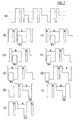
- Figure 4 shows the idealised "waveform" derived by the processor from the data read from the array following a snap-shot, the peaks in the waveform representing the dark spaces detected. At zero torque, the "full height” portions are exactly as they would be in the basic design. The "half-height" portions created by the semi-transparent zones of the overlay 100 are shown as Wa, Wb, Wc.
- the processor can differentiate between full height and half height portions by performing two series of comparisons of the waveform with an upper reference level for torque determination and with a lower reference level for position determination.
- Figure 6 shows the situation where full torque is applied.
- the processor can readily determine the relative displacement of the two disk elements relative to one another (and hence the torque).
- Figure 7 it is always possible to identify the semi-transparent zone which is visible, either by direct measurement of its width or by measurement of the width of the gap following it when the leading edge is obscured by a full height spoke, or the gap preceding it when the trailing edge is so obscured.
- the spokes on the disk element 12 vary from 1.2x width to 3.0x width as shown diagrammatically. As shown an increment of 0.1x is applied to the width of alternate spokes, and this has the effect of making the gaps between spokes reduce progressively in the clockwise direction as viewed in Figure 8.
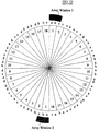
- Two arrays are employed at diametrically opposite positions and to ensure that a situation cannot occur where the only spokes which can be seen by each array, the pairs of spokes are staggered by the inclusion of two single spokes 110, 120 at non-opposite positions.
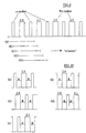
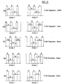
- the zero torque and maximum torque waveforms of Figures 9 to 12 show that wherever the array windows are located at the time of the snapshot it is always possible to determine the ratio between the gaps to determine the torque and the width of a spoke to identify the coarse position of the dark elements.
- the processor can use the variable spoke width data and the gap data to determine the torque and absolute position accurately.
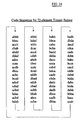
- the spokes on the two disk elements occur in the following sequences
- Figure 13 actually shows for each of 36 segments of the disc elements the spoke width which appears on the two disk elements.
- Figure 15 shows idealised waveforms for the two arrays at zero torque. Different array window positions at the instant of the snapshots result in the differing situations shown in Figure 16 which shows how a unique code sequence for the current angular position is determined.
Landscapes
- Physics & Mathematics (AREA)
- General Physics & Mathematics (AREA)
- Optical Transform (AREA)
- Length Measuring Devices By Optical Means (AREA)
Description
In the following description these separating portions are referred to as "spokes". There are an equal number (e.g. 36) of equi-angularly spaced spokes on each disk element and those on one disk element have a greater angular width than those on the other element.


Claims (12)
- A combined torque and angular position detector comprising a source of optical radiation (20), an array of optical sensors (22), first and second elements (10,12) interposed between the source and the array, said elements being rotatable together and also angularly movable relative to one another to a limited extent for torque measurement, said first and second elements each having a plurality of alternating first (16,18) and second regions, the first regions having greater optical transmissivities than the second regions, said second element also having further regions (100a) of optical transmissivity intermediate the transmissivities of the first and second regions, said further regions each being of different angular width, and a data processor (24) arranged to collect optical intensity data from each of the sensors of the array and arranged to process such data to determine the angular position of the second element by measuring the width and position of an image of a detected one of said further regions thereon, and the relative angular displacement of the first and second elements by measuring the position of the image of a second region of the second element relative to the positions of the images of two adjacent second regions of the first element.
- A detector as claimed in Claim 1 in which said data processor is arranged to determine the positions of the images of said first and second regions by comparing the optical intensity data for each sensor of the array with an upper threshold value.
- A detector as claimed in Claim 2 in which said data processor is arranged to determine the positions of the images of said further regions by comparing the intensity data for each sensor in the array with a lower threshold value.
- A detector as claimed in any preceding claim in which said further regions of said second element are arranged to lie centrally within respective ones of the first regions thereof.
- A detector as claimed in any preceding claim in which the second element comprises a first mask defining said first and second regions laminated with a transparent overlay which has semi-transparent areas forming said further regions.
- A combined torque and angular position sensor comprising a source of optical radiation (20), an array of optical sensors (22) illuminated by said source, first and second elements (10,12) interposed between the source and the array, said first and second elements being rotatable together and angularly movable relative to one another to a limited extent for torque measurement, each of said first and second elements having a plurality of alternating first (16,18) and second regions, said first regions having greater optical transmissivities than the second regions, the second regions of the second element varying in angular width such that the angular widths of the first regions thereof decrease progressively around said second element, and a data processor (24) connected to receive optical intensity data from each of the sensors of the array and arranged to process such data to determine the angular position of the second element by measuring the position and width of the image of the second regions of the second element, and the relative angular displacement between the elements by measuring the position of an image of a second region of the first element relative to the positions of images of two adjacent second regions of the second element.
- A detector as claimed in Claim 6 in which said second regions of the second element have centre lines which are equi-angularly spaced around said second element.
- A detector as claimed in Claim 7 in which there are two sensor arrays at diametrically opposite positions.
- A detector as claimed in Claim 8 in which the second regions of the second element are arranged mainly in adjacent pairs around the second element, the two second regions of each pair being of the same angular width.
- A detector as claimed in Claim 9 in which the pairs of regions are staggered relative to one another by the inclusion of two single second regions at non-opposite positions.
- A combined torque and angular position sensor comprising a source of optical radiation (20), an array of optical sensors (22) illuminated by said source, first and second elements (10,12) interposed between the source and the array, said first and second elements being rotatable together and also angularly movable relative to one another to a limited extent for torque measurement, each of the first and second elements having a plurality of alternating first (16,18) and second regions, the first regions being of greater optical transmissivity than the second regions, the device being arranged to form a combined image of a zone of said elements on the array, the widths of said second regions differing from one another such that in any position of the first and second element, images of second regions having a unique combination of angular widths are obtainable, and a data processor (24) connected to receive optical intensity data from each of the sensors of the array and arranged to operate on such data to determine a first measurement of the angular position of the elements by identifying which unique combination occurs in the image, a second measurement, finer than the first, of angular position in accordance with the position of the image of a selected second region within the image and the relative angular position of the elements by determining the position of the image of a second region of one element relative to the images of two adjacent second regions of the other element.
- A detector as claimed in Claim 11 in which two sources and two arrays are provided at diametrically opposite positions relative to the common axis of the first and second elements.
Applications Claiming Priority (3)
| Application Number | Priority Date | Filing Date | Title |
|---|---|---|---|
| GBGB9802064.7A GB9802064D0 (en) | 1998-01-31 | 1998-01-31 | Combined torque and angular position sensor |
| GB9802064 | 1998-01-31 | ||
| PCT/GB1999/000301 WO1999039169A1 (en) | 1998-01-31 | 1999-01-28 | Combined torque and angular position sensor |
Publications (2)
| Publication Number | Publication Date |
|---|---|
| EP0972176A1 EP0972176A1 (en) | 2000-01-19 |
| EP0972176B1 true EP0972176B1 (en) | 2002-07-24 |
Family
ID=10826208
Family Applications (1)
| Application Number | Title | Priority Date | Filing Date |
|---|---|---|---|
| EP99902697A Expired - Lifetime EP0972176B1 (en) | 1998-01-31 | 1999-01-28 | Combined torque and angular position sensor |
Country Status (8)
| Country | Link |
|---|---|
| US (1) | US6285024B1 (en) |
| EP (1) | EP0972176B1 (en) |
| JP (1) | JP2001519914A (en) |
| KR (1) | KR20010005766A (en) |
| BR (1) | BR9904813A (en) |
| DE (1) | DE69902209T2 (en) |
| GB (1) | GB9802064D0 (en) |
| WO (1) | WO1999039169A1 (en) |
Families Citing this family (23)
| Publication number | Priority date | Publication date | Assignee | Title |
|---|---|---|---|---|
| DE10003738A1 (en) * | 2000-01-28 | 2001-08-09 | Bosch Gmbh Robert | Torque detection device for e.g. shaft control of vehicle has optical scanner which evaluates relative rotation of codings on concentric encoder disks so that torque on connecting bodies can be determined |
| US6563109B1 (en) * | 2000-11-27 | 2003-05-13 | Kir Kupplungstechnik Gmbh | Apparatus for optoelectronically determining power using a light source being of annular design |
| JP2002242829A (en) * | 2001-02-16 | 2002-08-28 | Sanden Corp | Variable displacement compressor |
| US6817528B2 (en) * | 2001-07-17 | 2004-11-16 | Honeywell International Inc. | Reflective apparatus and method for optically sensing relative torque employing Moirè fringes |
| GB0212465D0 (en) | 2002-05-30 | 2002-07-10 | Trw Ltd | A vehicle steering system |
| WO2005068962A1 (en) | 2004-01-20 | 2005-07-28 | Valeo Schalter Und Sensoren Gmbh | Device for determining a steering angle and a torque that is exerted on a steering shaft |
| KR100629796B1 (en) * | 2004-09-07 | 2006-09-28 | 현대모비스 주식회사 | Absolute steering angle or torque measurement method using optical method |
| JP4483548B2 (en) * | 2004-11-25 | 2010-06-16 | パナソニック電工株式会社 | Massage machine |
| FI118979B (en) * | 2005-04-29 | 2008-05-30 | Metso Automation Oy | Procedure for measuring consistency, circuit breaker design and consistency meter |
| DE102005047258A1 (en) * | 2005-10-01 | 2007-04-05 | Dr. Johannes Heidenhain Gmbh | Position measuring device |
| US8352149B2 (en) * | 2008-10-02 | 2013-01-08 | Honeywell International Inc. | System and method for providing gas turbine engine output torque sensor validation and sensor backup using a speed sensor |
| WO2011066066A2 (en) * | 2009-11-30 | 2011-06-03 | Bi Technologies Corporation | Rotation and differential angle optical sensors |
| US8077301B2 (en) * | 2009-11-30 | 2011-12-13 | Bi Technologies Corporation | Rotation and differential angle optical sensor with integral bearing races |
| US8218134B2 (en) | 2009-11-30 | 2012-07-10 | Bi Technologies Corporation | Rotation and differential angle optical sensor with non-transition pattern sampling |
| US8077302B2 (en) | 2009-11-30 | 2011-12-13 | Bi Technologies Corporation | Rotation and differential angle optical sensor which does not require keyed installation |
| US8077303B2 (en) * | 2009-11-30 | 2011-12-13 | Bi Technologies Corporation | Rotation and differential angle optical sensor with short optical sensing array |
| US8171805B2 (en) * | 2010-02-18 | 2012-05-08 | Honeywell International Inc. | Non-contact torque determination system and method for a non-mechanically coupled rotating system |
| CN104024803B (en) * | 2011-10-31 | 2017-02-15 | 日本精工株式会社 | Torque detection device and electric power steering device |
| US9519254B2 (en) | 2014-12-17 | 2016-12-13 | Lexmark International, Inc. | Systems for configuring settings of an electronic device for customization thereof |
| US9964891B2 (en) | 2014-12-17 | 2018-05-08 | Lexmark International, Inc. | Systems for optical communication between an image forming device and a replaceable unit of the image forming device |
| US10282721B2 (en) | 2015-06-10 | 2019-05-07 | Lexmark International, Inc. | System and method for price verification in a retail environment |
| CA3127859A1 (en) * | 2019-01-25 | 2020-07-30 | 4Iiii Innovations Inc. | Virtual inertia enhancements in bicycle trainer resistance unit |
| CN114893426B (en) * | 2022-06-24 | 2023-03-31 | 珠海格力电器股份有限公司 | Oscillating fan and control method thereof |
Family Cites Families (5)
| Publication number | Priority date | Publication date | Assignee | Title |
|---|---|---|---|---|
| US4678908A (en) * | 1983-07-25 | 1987-07-07 | Bei Electronics, Inc. | Zero reference generating method and apparatus for optical encoders |
| US4866268A (en) | 1988-05-20 | 1989-09-12 | General Motors Corporation | Optical fast synchronization shaft position and speed sensor |
| GB9202868D0 (en) | 1992-02-12 | 1992-03-25 | Lucas Ind Plc | Optical torque sensors and steering systems for vehicles incorporating them |
| GB9316851D0 (en) * | 1993-08-13 | 1993-09-29 | Lucas Ind Plc | Enhanced position signals in optical torque sensors |
| EP1001256B1 (en) * | 1994-08-25 | 2001-03-28 | TRW LucasVarity Electric Steering Limited | Displacement sensor and torque sensor |
-
1998
- 1998-01-31 GB GBGB9802064.7A patent/GB9802064D0/en not_active Ceased
-
1999
- 1999-01-28 JP JP53905899A patent/JP2001519914A/en active Pending
- 1999-01-28 KR KR1019997008837A patent/KR20010005766A/en not_active Abandoned
- 1999-01-28 EP EP99902697A patent/EP0972176B1/en not_active Expired - Lifetime
- 1999-01-28 DE DE69902209T patent/DE69902209T2/en not_active Expired - Fee Related
- 1999-01-28 BR BR9904813-2A patent/BR9904813A/en not_active Application Discontinuation
- 1999-01-28 US US09/402,143 patent/US6285024B1/en not_active Expired - Fee Related
- 1999-01-28 WO PCT/GB1999/000301 patent/WO1999039169A1/en not_active Ceased
Also Published As
| Publication number | Publication date |
|---|---|
| WO1999039169A1 (en) | 1999-08-05 |
| GB9802064D0 (en) | 1998-03-25 |
| KR20010005766A (en) | 2001-01-15 |
| DE69902209T2 (en) | 2003-03-06 |
| DE69902209D1 (en) | 2002-08-29 |
| EP0972176A1 (en) | 2000-01-19 |
| BR9904813A (en) | 2000-05-23 |
| JP2001519914A (en) | 2001-10-23 |
| US6285024B1 (en) | 2001-09-04 |
Similar Documents
| Publication | Publication Date | Title |
|---|---|---|
| US6285024B1 (en) | Combined torque and angular position sensor | |
| EP1816441B1 (en) | Encoder | |
| US5241172A (en) | Variable pitch position encoder | |
| EP1001256B1 (en) | Displacement sensor and torque sensor | |
| EP0765039B1 (en) | Rotary encoder | |
| US6800843B2 (en) | Displacement and torque sensor | |
| AU2002249382A1 (en) | Optical displacement sensor | |
| CN100453976C (en) | Encoder | |
| GB2217837A (en) | "adjusting vehicle body height" | |
| CA2350877C (en) | Timing ruler or timing disk | |
| JPH063164A (en) | Rotational position detector | |
| JPH07134045A (en) | Absolute encoder | |
| AU2005287781B2 (en) | Method and arrangement for compensating errors in displacement or angle sensors | |
| JP2019215306A (en) | Optical rotary encoder | |
| JPH08304112A (en) | Vernier absolute encoder | |
| AU744805B2 (en) | Angle encoder | |
| EP1111358A2 (en) | Optical torque sensor | |
| KR20030081808A (en) | Digital optical angle sensor | |
| EP0175616A3 (en) | Optical shaft encoder | |
| JPH0758204B2 (en) | Absolute encoder | |
| JPH063162A (en) | Photoelectric absolute encoder | |
| JPH0372212A (en) | Position detecting apparatus |
Legal Events
| Date | Code | Title | Description |
|---|---|---|---|
| PUAI | Public reference made under article 153(3) epc to a published international application that has entered the european phase |
Free format text: ORIGINAL CODE: 0009012 |
|
| AK | Designated contracting states |
Kind code of ref document: A1 Designated state(s): DE FR GB IT |
|
| RAP1 | Party data changed (applicant data changed or rights of an application transferred) |
Owner name: LUCAS INDUSTRIES LIMITED |
|
| RAP1 | Party data changed (applicant data changed or rights of an application transferred) |
Owner name: TRW LUCAS VARITY ELECTRIC STEERING LIMITED |
|
| RAP1 | Party data changed (applicant data changed or rights of an application transferred) |
Owner name: TRW LUCAS VARITY ELECTRIC STEERING LIMITED |
|
| 17P | Request for examination filed |
Effective date: 19990921 |
|
| GRAG | Despatch of communication of intention to grant |
Free format text: ORIGINAL CODE: EPIDOS AGRA |
|
| 17Q | First examination report despatched |
Effective date: 20010924 |
|
| GRAG | Despatch of communication of intention to grant |
Free format text: ORIGINAL CODE: EPIDOS AGRA |
|
| GRAH | Despatch of communication of intention to grant a patent |
Free format text: ORIGINAL CODE: EPIDOS IGRA |
|
| GRAH | Despatch of communication of intention to grant a patent |
Free format text: ORIGINAL CODE: EPIDOS IGRA |
|
| GRAA | (expected) grant |
Free format text: ORIGINAL CODE: 0009210 |
|
| AK | Designated contracting states |
Kind code of ref document: B1 Designated state(s): DE FR GB IT |
|
| REG | Reference to a national code |
Ref country code: GB Ref legal event code: FG4D |
|
| REF | Corresponds to: |
Ref document number: 69902209 Country of ref document: DE Date of ref document: 20020829 |
|
| ET | Fr: translation filed | ||
| REG | Reference to a national code |
Ref country code: GB Ref legal event code: 732E |
|
| PLBE | No opposition filed within time limit |
Free format text: ORIGINAL CODE: 0009261 |
|
| STAA | Information on the status of an ep patent application or granted ep patent |
Free format text: STATUS: NO OPPOSITION FILED WITHIN TIME LIMIT |
|
| 26N | No opposition filed |
Effective date: 20030425 |
|
| PGFP | Annual fee paid to national office [announced via postgrant information from national office to epo] |
Ref country code: GB Payment date: 20041210 Year of fee payment: 7 |
|
| PGFP | Annual fee paid to national office [announced via postgrant information from national office to epo] |
Ref country code: FR Payment date: 20060104 Year of fee payment: 8 |
|
| PG25 | Lapsed in a contracting state [announced via postgrant information from national office to epo] |
Ref country code: GB Free format text: LAPSE BECAUSE OF NON-PAYMENT OF DUE FEES Effective date: 20060128 |
|
| PGFP | Annual fee paid to national office [announced via postgrant information from national office to epo] |
Ref country code: IT Payment date: 20060131 Year of fee payment: 8 |
|
| REG | Reference to a national code |
Ref country code: GB Ref legal event code: 732E |
|
| GBPC | Gb: european patent ceased through non-payment of renewal fee |
Effective date: 20060128 |
|
| REG | Reference to a national code |
Ref country code: FR Ref legal event code: ST Effective date: 20070930 |
|
| PG25 | Lapsed in a contracting state [announced via postgrant information from national office to epo] |
Ref country code: FR Free format text: LAPSE BECAUSE OF NON-PAYMENT OF DUE FEES Effective date: 20070131 |
|
| PGFP | Annual fee paid to national office [announced via postgrant information from national office to epo] |
Ref country code: DE Payment date: 20090130 Year of fee payment: 11 |
|
| PG25 | Lapsed in a contracting state [announced via postgrant information from national office to epo] |
Ref country code: IT Free format text: LAPSE BECAUSE OF NON-PAYMENT OF DUE FEES Effective date: 20070128 |
|
| PG25 | Lapsed in a contracting state [announced via postgrant information from national office to epo] |
Ref country code: DE Free format text: LAPSE BECAUSE OF NON-PAYMENT OF DUE FEES Effective date: 20100803 |