EP0971484A1 - Balancing receiver for a cellular radio communications system - Google Patents
Balancing receiver for a cellular radio communications system Download PDFInfo
- Publication number
- EP0971484A1 EP0971484A1 EP99401732A EP99401732A EP0971484A1 EP 0971484 A1 EP0971484 A1 EP 0971484A1 EP 99401732 A EP99401732 A EP 99401732A EP 99401732 A EP99401732 A EP 99401732A EP 0971484 A1 EP0971484 A1 EP 0971484A1
- Authority
- EP
- European Patent Office
- Prior art keywords
- frequency
- carrier
- rach
- bcch
- signal
- Prior art date
- Legal status (The legal status is an assumption and is not a legal conclusion. Google has not performed a legal analysis and makes no representation as to the accuracy of the status listed.)
- Granted
Links
- 230000001413 cellular effect Effects 0.000 title claims description 11
- 238000004891 communication Methods 0.000 title description 13
- 238000001228 spectrum Methods 0.000 claims description 22
- 238000001914 filtration Methods 0.000 claims description 21
- 230000017105 transposition Effects 0.000 claims description 18
- 230000005540 biological transmission Effects 0.000 claims description 16
- 230000008929 regeneration Effects 0.000 claims description 6
- 238000011069 regeneration method Methods 0.000 claims description 6
- 230000008878 coupling Effects 0.000 claims description 4
- 238000010168 coupling process Methods 0.000 claims description 4
- 238000005859 coupling reaction Methods 0.000 claims description 4
- 230000001172 regenerating effect Effects 0.000 claims description 3
- 238000002347 injection Methods 0.000 claims 1
- 239000007924 injection Substances 0.000 claims 1
- 230000002035 prolonged effect Effects 0.000 claims 1
- 238000000034 method Methods 0.000 abstract description 2
- 239000000969 carrier Substances 0.000 description 50
- 230000006870 function Effects 0.000 description 16
- 238000001514 detection method Methods 0.000 description 7
- 230000000694 effects Effects 0.000 description 4
- 230000011664 signaling Effects 0.000 description 4
- 230000001360 synchronised effect Effects 0.000 description 4
- 101100438241 Arabidopsis thaliana CAM5 gene Proteins 0.000 description 3
- 101100221077 Arabidopsis thaliana CML12 gene Proteins 0.000 description 3
- 101100167667 Arabidopsis thaliana CML24 gene Proteins 0.000 description 3
- 101100429139 Arabidopsis thaliana XTH22 gene Proteins 0.000 description 3
- 239000003086 colorant Substances 0.000 description 3
- 238000010586 diagram Methods 0.000 description 3
- 238000005259 measurement Methods 0.000 description 3
- 238000011144 upstream manufacturing Methods 0.000 description 3
- 230000002238 attenuated effect Effects 0.000 description 2
- 230000008901 benefit Effects 0.000 description 2
- 230000035945 sensitivity Effects 0.000 description 2
- RYGMFSIKBFXOCR-UHFFFAOYSA-N Copper Chemical compound [Cu] RYGMFSIKBFXOCR-UHFFFAOYSA-N 0.000 description 1
- 230000003321 amplification Effects 0.000 description 1
- 230000008859 change Effects 0.000 description 1
- 230000001276 controlling effect Effects 0.000 description 1
- 229910052802 copper Inorganic materials 0.000 description 1
- 239000010949 copper Substances 0.000 description 1
- 230000001934 delay Effects 0.000 description 1
- 230000003111 delayed effect Effects 0.000 description 1
- 238000013461 design Methods 0.000 description 1
- 238000009434 installation Methods 0.000 description 1
- 230000010354 integration Effects 0.000 description 1
- 238000005305 interferometry Methods 0.000 description 1
- 238000007726 management method Methods 0.000 description 1
- 238000003199 nucleic acid amplification method Methods 0.000 description 1
- 239000013307 optical fiber Substances 0.000 description 1
- 238000013439 planning Methods 0.000 description 1
- 230000000306 recurrent effect Effects 0.000 description 1
- 230000009467 reduction Effects 0.000 description 1
- 230000001105 regulatory effect Effects 0.000 description 1
- 238000013468 resource allocation Methods 0.000 description 1
- 230000000630 rising effect Effects 0.000 description 1
- 230000002123 temporal effect Effects 0.000 description 1
- 238000012360 testing method Methods 0.000 description 1
- 238000012546 transfer Methods 0.000 description 1
Images
Classifications
-
- H—ELECTRICITY
- H04—ELECTRIC COMMUNICATION TECHNIQUE
- H04B—TRANSMISSION
- H04B1/00—Details of transmission systems, not covered by a single one of groups H04B3/00 - H04B13/00; Details of transmission systems not characterised by the medium used for transmission
- H04B1/06—Receivers
- H04B1/10—Means associated with receiver for limiting or suppressing noise or interference
- H04B1/12—Neutralising, balancing, or compensation arrangements
- H04B1/123—Neutralising, balancing, or compensation arrangements using adaptive balancing or compensation means
Definitions
- the present invention relates to a cellular radio system as well as to a system incorporating it, including a system of GSM 900 or DCS 1800 radio communication.
- GSM Global System for Mobiles
- Figure 1 One such system (Figure 1) includes stations mobiles and fixed means of communication.
- MS Mobile stations are physical equipment used by system users. It's about in particular devices denoted MS in FIG. 1 and which may be vehicle-mounted stations, portable stations, or portable telephones.
- the fixed means of communication include base stations (Base Transmitter Station, in English) hereinafter called BTS, to exchange (emission and reception) of speech or data signals with mobile stations.
- BTS Base Transmitter Station
- BTS provide a function of modulation / demodulation of radio carriers by these speech or data signals, and a function transposition and multiplexing / demultiplexing of these radio carriers in the band allocated to the operator.
- each BTS includes means hardware and software for signal exchange radio stations with mobile stations located in its coverage area, in each of the two directions possible.
- each BTS includes transmitters / receivers in number equal to the number of radio carriers used by BTS.
- these devices are called TRX.
- each BTS is linked to at least one antenna performing the interface with air.
- fixed radio transmission / reception equipment provide power amplification and coupling to antennas for carrier transmission modulated. In the following, these devices are called relay.
- BTS area The coverage area of a BTS, i.e. the geographic area in which communications with mobile stations are transmitted by through this BTS, is called BTS area or sector.
- BTS area The geographic area covered by the system is thus segmented into a network of sectors, also called "mobile network”.
- the fixed means of communication of the system also include base station controllers (Base Stations Controller, in English), below called BSC, providing a command and control function BTS control.
- BSC Base Stations Controller
- Each BTS is linked to a BSC.
- Each BSC can be linked to one or more BTS for order and control them.
- MSC Mobiles Services Commutator, in English
- PSTN network dial-up telephone
- ISDN digital integration network of service
- interface A The interface between an MSC and a BSC is called interface A and the interface between a BSC and a BTS is called Abis interface.
- These are wired links (twisted copper pairs) supporting a flow digital about 2 Mbits / s (megabits per second). These interfaces are standardized so as to allow the assembly of equipment of various origins.
- a system can only use carriers located in a first frequency band between 890 and 915 MHz (megahertz) for the mobile network direction to fixed network (called uplink) and in a second frequency band between 935 and 960 MH for the fixed network to mobile network direction (called downward path).
- a carrier of the first band and a carrier of the second band are combined to constitute a two-way telephone circuit.
- the gap between these two carriers is called duplex gap. This gap is constant. For a GSM 900 type system, it is 45 MHz.
- a group of several carriers of the first band (and their associated carriers of the second band) are assigned to a group of several BTS whose sectors are geographically not contiguous.
- the carriers are divided into twelve groups of five carriers (two carriers not used).
- color we will use the expression "color" to designate such a group of carriers. These twelve colors are respectively assigned to twelve sectors geographically contiguous.
- Three BTS whose sectors S1, S2 and S3 are adjacent, are grouped on the same site called base, and are connected respectively to three antennas directives oriented in directions at 120 ° one the other. These three sectors form a C1 cell. Similarly, three other cells C2, C3 and C4 are formed each of three sectors each covering an angle of 120 °, respectively S4-S6, S7-S9, and S10-S12. We are talking tri-sectoral cells. At the center of each cell is a base housing the BTS of the three cell sectors.
- a cell is commonly represented in a way stylized by a hexagon, as we can see at the figure 1.
- the geographic area covered by the radiocommunication is therefore segmented into a network of tri-sectoral units, with an allocation plan frequencies consisting of a basic pattern to four cells and twelve colors reproduced as many times as necessary, by abuse of language, the terms "sector” and "cell” will be used indiscriminately in the continued to designate a BTS area.
- a given BTS therefore uses the frequencies of a single color for communications with the mobiles present in the cell to which it is associated.
- BTS therefore include as many TRX that there are carriers in the color.
- the BTS include five TRX.
- time axis is divided into intervals Time Slots, below called IT, whose duration is equal to 0.577 ms. Eight such consecutive intervals form a frame. A frame therefore lasts 4.6 ms.
- IT are identified by a number from zero to seven. recurrent IT with the same number constitutes a physical channel for data transmission or the speech. In fact, only seven IT per frame are available for the transmission of useful data. So seven physical channels are available per carrier.
- GSM 900 radio communication use the possibility, provided by GSM 05-05 standard, frequency hopping slow.
- this functionality consists of modify periodically (with each frame, either every 4.6 ms) assigning colors to different sectors of the basic pattern of the mobile network.
- This frequency hopping allows distribution among several physical channels the effect of a possible jammer which would disrupt a specific frequency. This distribution results in a linearization of the report signal / noise of the different physical channels and, for example therefore, by improving the overall quality radio communications.
- bits of useful information are service bits, including signaling and synchronization.
- the bits of service include a 26 bit sequence arranged in the middle of the train, called "sequence learning ", chosen for its good properties autocorrelation. This sequence has the function of allow synchronization of the physical channel despite the multipath phenomena inherent in any radio propagation.
- Logical channels are of two types: on the one hand Traffic Channels, below called TCH channels, and on the other hand control or signaling (Control Channel, in English), hereinafter called CCH channels.
- TCH channels Traffic Channels
- CCH channels Control Channel, in English
- the former are used for speech transmission or data produced by users (carriers which support TCH channels are sometimes called conversation carriers or traffic carriers).
- the CCH channels include a broadcast channel (Broadcast Control Channel, in English), hereinafter the BCCH channel, which provides mobile stations with information relating to the cell in which they are located as well as to neighboring cells.
- the BCCH channel is a channel in the fixed network to mobile network direction.
- the carrier which supports this channel hereinafter called “F BCCH carrier” or “beacon carrier”, is transmitted at constant frequency and without level regulation (in fact, it is transmitted at the maximum power available).
- a carrier F BCCH is associated with each sector of the basic pattern.
- a basic pattern mobile network with n sectors therefore requires at least n carriers F BCCH .
- the F BCCH carriers are not subject to the slow frequency hopping.
- Each mobile station includes means for measuring the level of all the F BCCH carriers which it is obliged to measure, namely the F BCCH carrier associated with the cell in which it is located, and the F BCCH carriers associated with the adjacent cells. to this cell.
- the mobile stations also include means for sending a measurement report after calculating an average over a certain number of measurements, this report including information on the quality of the information received with a view to enabling intercellular switching (hand-over, in English) required by the mobile nature of users.
- the quality of the information received is determined by calculating an error rate.
- CCH channels include a Random Access Control Channel, hereinafter RACH channel.
- RACH channel is a channel in the mobile network to fixed network direction.
- the carrier which supports this channel hereinafter called “carrier F RACH”
- carrier F RACH has a frequency f RACH offset with respect to the frequency f BCCH of the carrier F BCCH by a determined deviation whose value is that of the duplex deviation mentioned above, ie 45 MHz for a system conforming to the GSM 900 standard.
- the carrier F RACH is below the carrier F BCCH and the difference between the two is constant. It is worth 45 MHz for a system compliant with the GSM 900 standard and 95 MHz for a system compliant with the DCS 1800 standard.
- the physical channel supporting the RACH channel is offset by three time slots ("Time Slots") in the delay direction, relative to the physical channel supporting the BCCH channel.
- the carrier F RACH is transmitted at the maximum available power, in particular when the mobile station is started up.
- the mobile station includes means for measuring the level of the F BCCH carriers it can receive and for searching for the carrier whose level is maximum, as well as means for transmitting an acknowledgment message on the associated duplex RACH channel. to the BCCH channel corresponding to this carrier. By sending this acknowledgment message, the mobile station makes a request for allocation of resources, with a view to establishing a call.
- a receiver system receiver is provided.
- cellular radio such as the system described above. More specifically, the receiver is a broadband receiver for a repeater multicarrier, placed at the head of the means of fixed communication in the transmission chain up (mobile network to fixed network).
- GSM carriers in particular an F RACH carrier
- BTS entry i.e. directly if the BTS and the means transmission / reception are on the same site, either after transmission over a link if the installation site of the BTS and the transmission / reception site are distant.
- microcell a group of streets
- Many microcells depend on the same BTS and the binding between the BTS and the transmitting / receiving boxes is performed on optical fiber or coaxial cable, or even by radio link, by transposition of appropriate frequency at each end.
- the carrier F RACH is transmitted by the mobile stations at the maximum power available, that is to say at a power of the order of 1 Watt for a portable telephone of class 5.
- the carrier F RACH therefore presents a level much higher than that of other carriers (carriers of traffic).
- the level of the F RACH carrier can be 20 to 40 dB higher than the other carriers of the multifrequency signal.
- Certain equipment comprising means for adjusting their sensitivity, for example automatic gain control devices, the sensitivity of this equipment can then be suddenly reduced due to the appearance of the carrier F RACH in the spectrum, so that the modulation of other carriers by information and / or speech signals from other mobile stations may not be detected correctly.
- the uplink transmission chain is "dazzled" by the carrier F RACH .
- the present invention aims to propose means to resolve this problem.
- the invention provides a receiver for cellular radio system including a GSM 900 or DCS standard compliant system 1800 which includes the first means to transmit, in the fixed network to mobile network direction, a signal multifrequency having a spectrum which includes a beacon carrier whose frequency is fixed, and second means for transmitting, in the network direction mobile to fixed network, a multi-frequency signal having a spectrum which includes a random access carrier whose frequency is offset by a difference determined by with respect to the frequency of said beacon carrier.
- a receiver for cellular radio system including a GSM 900 or DCS standard compliant system 1800 which includes the first means to transmit, in the fixed network to mobile network direction, a signal multifrequency having a spectrum which includes a beacon carrier whose frequency is fixed, and second means for transmitting, in the network direction mobile to fixed network, a multi-frequency signal having a spectrum which includes a random access carrier whose frequency is offset by a difference determined by with respect to the frequency of said beacon carrier.
- the receiver according to the invention comprises a selective level reduction device only carrier of random access when this is greater than a determined threshold.
- the selective attenuation device is an interferometric device ensuring attenuation by coupling, in phase opposition and at level required, an attenuation signal at the frequency of the carrier of random access.
- Such a device presents good linearity properties and therefore allows not strongly distort the rest of the signal spectrum multifrequency.
- the selective attenuation device includes narrow band filtering means operating at a low intermediate frequency or at zero intermediate frequency, as well as first means of transposition to ensure transposition of the multi-frequency signal at this frequency intermediate before filtering, and second means of transposition to restore the multi-frequency signal in its original band after filtering.
- a low intermediate frequency is a frequency of low value compared to frequency values GSM which are between 900 and 1000 MHz.
- GSM frequency values
- a low frequency is around a few tens of megahertz at most.
- This intermediate frequency will be fixed whatever the frequency of the carriers F BCCH and F RACH , by changing the frequency of the local transposition oscillator, subject to the frequency of the carrier F BCCH .
- Transposing the multi-frequency signal to a low intermediate frequency, before filtering, allows use a narrow band filter with high rejection which is simpler to carry out and therefore more economical than a filter with the same properties but having to operate in the band between 900 and 1000 MHz.
- the invention also provides a system for cellular radio communication incorporating a receiver like the one described above.
- a BTS broadcasts (in the fixed network to mobile network direction) a signal to mobile stations in the covered cell, which is a multi-frequency signal that is to say whose spectrum includes several carrier frequencies in the useful band.
- the carriers are GSM carriers.
- TCH carriers there are carriers of conversation or traffic (or TCH carriers), possibly subject to frequency hopping all the 4.6 ms and transmitted at varying levels of a time slot ("Time Slot") to the next.
- TCH carriers can be modulated by signals information and / or speech.
- tag carrier (or carrier BCCH) not subject to frequency hopping and issued at a constant level.
- This carrier is modulated by signaling signals and / or synchronization.
- a signal can contain seven carriers spread over thirty two possible positions in a band between 935.2 MHz and 941.8 MHz. Possible positions in this band are spaced by a step of 200 kHz.
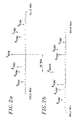
- FIG. 2a the spectrum of such a signal is shown at a given time. It includes a beacon carrier, denoted F BCCH in the figure, located at one position among eight possible positions on the frequency axis. These eight possible positions are preferably located in the middle of the useful band. The advantage of this arrangement will be explained later.
- F BCCH beacon carrier
- the position occupied by the carrier F BCCH among the eight possible positions does not vary over time, since this carrier is not subject to frequency hopping. This position depends on the cell to which the BTS considered corresponds within the basic pattern of the cellular network.
- the signal spectrum also comprises three traffic carriers (denoted F TCH1 , F TCH2 , F TCH3 ) which can respectively occupy three distinct positions among twelve possible positions in the lower part of the useful band.
- the spectrum includes three other traffic carriers (denoted F TCH4 , F TCH5 , F TCH6 ) which can respectively occupy three distinct positions among the twelve possible positions in the upper part of the useful band. These six TCH carriers occupy a variable position over time, as a function of the frequency hopping.
- a combination of positions occupied by carriers is determined by the operator and results from choices involved in frequency planning available.
- a combination of carriers such as that shown in Figure 2a is a color in the sense indicated in the introduction.
- FIG. 2b the spectrum of a signal emitted, when it is put into operation, by a mobile station present in the area covered by the even BTS.
- the useful band of this signal is shifted, towards the lower frequencies, 45 MHz (duplex deviation for a GSM 900 system) relative to the useful band of the signal of Figure 2a.
- the spectrum of FIG. 2b comprises a carrier F RACH , which is shifted, towards the lower frequencies, by 45 MHz with respect to the carrier F BBCH included in the spectrum of the signal of FIG. 2a.
- the carrier F RACH is therefore advantageously in the middle of the useful band of the spectrum of FIG. 2b. This ranges from 890.2 MHz to 896.8 MHz. It is modulated by a signal for signaling and requesting resource allocation sent by a mobile station before the establishment of a call.
- the spectrum also comprises traffic carriers denoted F TCH1 ', F TCH2 ', F TCH3 ', F TCH4 ', F TCH5 ', and F TCH6 ' which are respectively offset by 45 MHz towards the lower frequencies, with respect to, respectively , to the carriers F TCH1 , F TCH2 , F TCH3 , F TCH4 , F TCH5 , and F TCH6 of the signal of FIG. 2a.
- These carriers can be modulated by information and / or speech signals transmitted by the mobile stations.
- the carrier F RACH can have a much higher level (from 20 to 40 dB) than that of the other carriers.
- the receiver according to the invention comprises a device for attenuating the level of the single carrier F RACH when the latter is greater than a determined threshold Vo.
- a selective attenuation device because it has effects only on the frequency f RACH of the carrier F RACH , without disturbing the other frequencies of carriers of the spectrum.
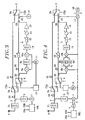
- Figure 3 is a diagram of a first mode of realization of a receiver according to the invention.
- the receiver has an antenna A to receive a multi-frequency signal from mobile stations located in the area covered by the receiver.
- the antenna is followed by a centered F1 bandpass filter on the useful band of this signal, namely the band between 890.2 and 896.8 MHz in the example.
- the filter output F1 is connected, via a delay line 20, at the common entrance of a radio frequency switch 5a, with one input and two exits.
- the output S of the receiver is taken on the output common of a second radio frequency switch 5b, to two inputs and one output.
- the first aforementioned channel of the receiver connects a first output of switch 5a to first input of switch 5b.
- the aforementioned second path connects the second output of switch 5a to the second switch input 5b.
- the signal received by the antenna A, filtered by the filter F1, and delayed by the line to delay 20, is transmitted directly to output S of the receiver through the first channel.
- this same signal is transmitted to the output S of the receiver by the second channel comprising the device for selective attenuation of the level of the carrier F RACH .
- switches 5a and 5b are controlled by the means of selection above. In Figure 3, these bear the SEL reference. They generate CSA control signals and CSB of the position of the switches respectively 5a and 5b.
- the function of the selection means SEL is to compare the level of the carrier F RACH to the threshold Vo and to generate the signals CSA and CSB accordingly.
- carrier level is meant, for example, the modulus of the vector radius of this carrier (expressed in volts).
- the means for detecting the level of the carrier F RACH comprises in series a coupler 2 disposed between the filter F1 and the delay line 20, a bandpass filter 3 centered on the useful band of the multifrequency signal, as well as a detector 1 linked to the selection means SEL.
- the coupler 2 allows part of the strength of the multifrequency signal received.
- the detector 1 performs direct detection of the level of the carrier F RACH .
- the selective attenuation device included in the second channel of the receiver circuit is preferably, but not necessarily, an interferometric device, that is to say ensuring attenuation by interferometry.
- an interferometric device injects by coupling, into the multifrequency signal, in phase opposition and at the required level, an attenuation signal at the frequency f RACH of the carrier F RACH .
- the receiver therefore comprises means for filtering and amplifying the carrier F RACH making it possible to generate this attenuation signal.
- the frequency f RACH of the carrier F RACH being a function of the cell in which the receiver is implanted, it would in principle be necessary as many such different means as there are cells in the basic pattern of the cellular network.
- the allocation of receivers to a particular cell should be changed.
- the means for generating the attenuation signal at the frequency f RACH of the carrier F RACH should be modified.
- the attenuation signal at the frequency f RACH is generated as a function of the frequency f BCCH of the carrier F BCCH in a simple and effective manner.
- the carrier F RACH is 45 MHz below the carrier F BCCH .
- the receiver according to the invention therefore comprises a circuit 12 for regenerating the frequency f BCCH of the tag carrier F BCCH .
- this circuit 12 is a circuit of a system mobile station designed to fill this function.
- the stations cellular radiocommunication system include such a circuit for continuously detecting the level of the cell beacon carrier in which they are found as well besides that the level of the tag carriers of the adjacent cells.
- a mobile station is quite simply permanently installed in the receiver in order to fulfill the role of a circuit for regenerating the frequency f BCCH of the carrier F BCCH .
- the interferometric device shown in FIG. 3 is an interference loop L, a direct branch of which comprises a delay line 22 in series with a variable attenuator 18, and a secondary branch of which comprises narrow-band filtering means making it possible to isolate the carrier F RACH .
- the secondary branch includes a coupler 25 arranged before the delay line 22 and a coupler 26 placed after the variable attenuator 18.
- the first and second transposition means each comprise a modulator 8a and 10a respectively.
- these first and second means advantageously comprise a single local oscillator 11 oscillating at a frequency which is a function of the frequency f BCCH of the regenerated carrier F BCCH , of the constant difference between the frequency of the carrier F BCCH and that of the carrier F RACH (duplex difference, which is equal to 45 MHz), and of the intermediate frequency.
- the intermediate frequency is low compared to GSM carrier frequencies contained in the signal multifrequency.
- the intermediate frequency is 10.7 MHz.
- the oscillator 11 is then controlled by the regeneration circuit 12 of the frequency of the carrier F BCCH , so as to oscillate at the frequency f BCCH -45 MHz -10.7 MHz.
- the filtering means comprise a bandpass filter 9a with a narrow band, centered on the intermediate frequency.
- the passband of the filter 9a is 200 KHz so as to keep only the carrier F RACH transposed to the intermediate frequency.
- the first means of transposition have the function of transposing the signal to be filtered at an intermediate frequency at which the filtering means are easier to perform.
- the intermediate frequency is worth 10.7 MHz and it's more easy to make a 200 KHz bandpass filter width at this frequency than at a GSM frequency of around 900 to 1000 MHz.
- the signal at the output of the second means of transposition 10a is filtered using a filter bandpass 14, then it is out of phase by means in particular variable phase shifter 15 and linearly amplified by means of an amplifier 19, respectively at the phase required (180 °) at the required level (some milliwatts) to constitute the signal for attenuation of the interferometric loop. It is then reinjected in the primary branch, in phase opposition, by through the coupler 26.
- the attenuation of the level of the carrier F RACH which is thus obtained is of the order of 20 to 30 dB.
- These means comprise a switch 6 with two inputs and an output, arranged in the second channel of the circuit, between the switch 5a and the coupler 25. More specifically, a first input of the switch 6 is connected to the second output of the switch 5a, and the output of the switch 6 is connected to the input of the coupler 25. The second input of the switch 6 is connected to the circuit 12 of regeneration of the carrier F BCCH to receive a pilot signal at the frequency f RACH from the carrier F RACH .
- the input of the second channel of the circuit is connected to the output of switch 5a which delivers the signal multi-frequency received by antenna A and filtered by filter F1.
- the input of the second channel of the circuit is connected to an output of the regeneration circuit 12 which delivers the pilot signal at the frequency f RACH and at known and constant level.
- This signal is introduced at the input of loop L. If it is properly adjusted, the signal at the output of loop L must have, at frequency f RACH , a level almost zero. In other words, the pilot signal injected at the input of loop L must theoretically have disappeared at the output of said loop.
- the circuit comprises means for measuring the residual level of the pilot signal at the output of the loop L. These means are means for measuring the level of the signal at the frequency f RACH at the output of the loop L. These means comprise a coupler 27 arranged in the second channel of the circuit, between the output of the coupler 26 and the second input of the switch 5b, as well as a detector 16.
- this detector 16 performs direct detection of the level of the signal at the frequency f RACH of the carrier F RACH .
- the variable attenuator 13 as well as the variable phase shifter 15 are adjusted as a function of this detection by means not shown.
- This measurement and these adjustments are carried out during test phases carried out in the absence of an F RACH carrier of a level greater than a determined threshold.
- the first channel has a line to delay 21 to compensate for the delay introduced by the second channel of the circuit when it is active.
- the delay of the transmitted signals is identical whichever channel is active.
- the lines to delay 21 and 22 also have the function of ensuring frequency stability of the loop balance.
- the circuit works as follows. In the absence of the threshold value Vo being exceeded by the carrier F RACH , the switches 5a and 5b are controlled by the means SEL so that the first channel is active.
- the switches 5a, 6 and 5b are controlled so that the second channel is active.
- the delay line 20 then has the function of allowing the switching of the switches 5a and 6 before the arrival of the multifrequency signal which must be selectively attenuated.
- the switch 6 is controlled so that the pilot signal at the frequency f RACH is injected into the second channel to ensure the adjustment of the loop L.
- the embodiment of Figure 4 is distinguished from that of FIG. 3 mainly in that the means for filtering the second branch of the device interferometric operate at frequency intermediate zero and no longer at frequency weak intermediate.
- the first modulation means and the second modulation means comprise first and second modulators in phase and in quadrature, respectively 8b and 10b, instead of modulators 8a and 10a respectively.
- the local oscillator 11 is controlled to oscillate at the frequency f BCCH -45MHz, that is to say at the frequency of the carrier F RACH .
- the narrow band filtering means then have a low pass filter 9b for the filtering of the phase I component, and a second low pass filter 9b 'for filtering the component in quadrature Q. These two filters have an equal width at 200 KHz and replace the filter 9a in Figure 3.
- the embodiment shown in Figure 4 differs from that shown in Figure 3 in that the means for detecting the level of the carrier F RACH after the filter F1 are synchronous detection means.
- the detector 1 of FIG. 3 is replaced by a synchronous detector 4 operating by detection on the component in phase I and on the component in quadrature Q after demodulation in phase and in quadrature by a demodulator 7.
- the means of measuring the level pilot signal residual are synchronous detection means.
- detector 16 is replaced by a detector synchronous 18 operating by detection on the component in phase I and on the component in quadrature Q after demodulation in phase and in quadrature by a demodulator 17.
- the demodulators 8b, 10b, 7 and 17 are controlled by the frequency generated by the local oscillator 11, namely the frequency f RACH of the carrier F RACH .
Landscapes
- Engineering & Computer Science (AREA)
- Computer Networks & Wireless Communication (AREA)
- Signal Processing (AREA)
- Mobile Radio Communication Systems (AREA)
Abstract
Description
La présente invention se rapporte à un récepteur de système de radiocommunication cellulaire ainsi qu'à un système l'incorporant, notamment un système de radiocommunication GSM 900 ou DCS 1800.The present invention relates to a cellular radio system as well as to a system incorporating it, including a system of GSM 900 or DCS 1800 radio communication.
Dans la suite, et à moins qu'il n'en soit disposé autrement, on considère l'exemple non limitatif d'un système de radiocommunication de type GSM. Les initiales GSM sont mises pour "Global System for Mobiles", ce qui, en anglais, signifie "Système Global pour les Mobiles".In the following, and unless it is disposed otherwise, we consider the nonlimiting example of a GSM type radio system. The GSM initials are set for "Global System for Mobiles ", which in English means" Global System for Mobiles ".
Un tel système (figure 1) comprend des stations mobiles et des moyens de communication fixes.One such system (Figure 1) includes stations mobiles and fixed means of communication.
Les stations mobiles sont les équipements physiques utilisés par les usagers du système. Il s'agit notamment des appareils notés MS à la figure 1 et qui peuvent être des stations montées en véhicule, des stations portables, ou des téléphones portatifs.Mobile stations are physical equipment used by system users. It's about in particular devices denoted MS in FIG. 1 and which may be vehicle-mounted stations, portable stations, or portable telephones.
Les moyens de communication fixes comprennent des stations de base (Base Transmitter Station, en anglais) ci-après appelées BTS, pour échanger (émission et réception) des signaux de parole ou de données avec les stations mobiles.The fixed means of communication include base stations (Base Transmitter Station, in English) hereinafter called BTS, to exchange (emission and reception) of speech or data signals with mobile stations.
Plus exactement, les BTS assurent une fonction de modulation/démodulation de porteuses radioélectriques par ces signaux de parole ou de donnée, et une fonction de transposition et de multiplexage/démultiplexage de ces porteuses radioélectriques dans la bande allouée à l'opérateur.More precisely, BTS provide a function of modulation / demodulation of radio carriers by these speech or data signals, and a function transposition and multiplexing / demultiplexing of these radio carriers in the band allocated to the operator.
A cet effet, chaque BTS comprend des moyens matériels et logiciels permettant l'échange de signaux radioélectriques avec les stations mobiles se trouvant dans sa zone de couverture, dans chacun des deux sens possibles.To this end, each BTS includes means hardware and software for signal exchange radio stations with mobile stations located in its coverage area, in each of the two directions possible.
Notamment, chaque BTS comprend des émetteurs/récepteurs en nombre égal au nombre de porteuses radioélectriques utilisées par la BTS. Dans la terminologie des systèmes GSM 900 et dans la suite, ces équipements sont appelés TRX.In particular, each BTS includes transmitters / receivers in number equal to the number of radio carriers used by BTS. In the terminology of GSM 900 systems and thereafter, these devices are called TRX.
De plus, chaque BTS est reliée à au moins une antenne réalisant l'interface avec l'air. En outre, des équipements fixes d'émission/réception radioélectrique assurent l'amplification de puissance et le couplage aux antennes pour la transmission des porteuses modulées. Dans la suite, ces équipements sont appelés relais.In addition, each BTS is linked to at least one antenna performing the interface with air. In addition, fixed radio transmission / reception equipment provide power amplification and coupling to antennas for carrier transmission modulated. In the following, these devices are called relay.
La zone de couverture d'une BTS, c'est-à-dire la zone géographique dans laquelle les communications avec les stations mobiles sont transmises par l'intermédiaire de cette BTS, est appelée zone de BTS ou secteur. L'aire géographique couverte par le système de radiocommunication est ainsi segmentée en un réseau de secteurs, dit aussi "réseau mobile".The coverage area of a BTS, i.e. the geographic area in which communications with mobile stations are transmitted by through this BTS, is called BTS area or sector. The geographic area covered by the system is thus segmented into a network of sectors, also called "mobile network".
Les moyens de communication fixes du système comprennent aussi des contrôleurs de stations de base (Base Stations Controller, en anglais), ci-après appelés BSC, assurant une fonction de commande et de contrôle des BTS. Chaque BTS est reliée à un BSC. Chaque BSC peut être relié à une ou plusieurs BTS pour les commander et les contrôler.The fixed means of communication of the system also include base station controllers (Base Stations Controller, in English), below called BSC, providing a command and control function BTS control. Each BTS is linked to a BSC. Each BSC can be linked to one or more BTS for order and control them.
Les moyens de communication fixes comportent enfin des commutateurs de services mobiles (Mobiles Services Commutator, en anglais), ci-après appelés MSC, assurant toutes les fonctions de commutation nécessaires pour les stations mobiles situés dans une partie, appelée zone de MSC, de la zone géographique couverte par le système. Dit autrement, un MSC est un autocommutateur de téléphonie. Il est relié à un ou des réseaux de télécommunication fixes, tels que le réseau téléphonique commuté (RTC) conçu pour le transport de la parole, ou le réseau numérique d'intégration de service (RNIS) conçu pour le transfert de la parole et de données. Il assure et met à jour la localisation des stations mobiles et applique les procédures prévues pour l'acheminement des communications en prenant en compte la nature mobile des usagers.Fixed means of communication finally include mobile service switches (Mobiles Services Commutator, in English), hereinafter called MSC, ensuring all switching functions necessary for mobile stations located in a part called MSC area, the geographic area covered by the system. In other words, an MSC is a PABX telephony. It is connected to one or more networks of fixed telecommunications, such as network dial-up telephone (PSTN) designed for the transport of speech, or the digital integration network of service (ISDN) designed for speech transfer and of data. It ensures and updates the location of mobile stations and applies planned procedures for routing communications by taking account for the mobile nature of the users.
L'interface entre un MSC et un BSC est appelée interface A et l'interface entre un BSC et une BTS est appelée interface Abis. Ce sont des liaisons filaires (paires torsadées en cuivre) supportant un débit numérique de l'ordre de 2 Mbits/s (mégabits par seconde). Ces interfaces sont normalisées de manière à permettre l'assemblage d'équipements de diverses origines.The interface between an MSC and a BSC is called interface A and the interface between a BSC and a BTS is called Abis interface. These are wired links (twisted copper pairs) supporting a flow digital about 2 Mbits / s (megabits per second). These interfaces are standardized so as to allow the assembly of equipment of various origins.
Selon les prescriptions de la norme GSM 05-05 un système ne peut utiliser que des porteuses se situant dans une première bande de fréquences comprise entre 890 et 915 MHz (mégahertzs) pour le sens réseau mobile vers réseau fixe (appelé voie montante) et dans une seconde bande de fréquence comprise entre 935 et 960 MH pour le sens réseau fixe vers réseau mobile (appelé voie descendante).According to the prescriptions of the GSM 05-05 standard a system can only use carriers located in a first frequency band between 890 and 915 MHz (megahertz) for the mobile network direction to fixed network (called uplink) and in a second frequency band between 935 and 960 MH for the fixed network to mobile network direction (called downward path).
Dans chacune de ces deux bandes, les systèmes ne peuvent en fait utiliser que 124 porteuses monofréquences déterminées, espacées avec un pas de 200 KHz (kilohertzs). Dans une aire géographique déterminée, l'usage exclusif de telle ou telle porteuse par tel ou tel système est réglementé par l'administration publique. Bien entendu, si plusieurs systèmes gérés par des opérateurs différents coexistent dans une même aire géographique, chaque opérateur veille à n'émettre que sur celles des 124 porteuses qui lui sont réservées, de manière à ne pas perturber les porteuses réservées à ses concurrents.In each of these two bands, the systems do not can actually only use 124 carriers determined single frequencies, spaced at a step of 200 KHz (kilohertzs). In a geographical area determined, the exclusive use of this or that carrier by such and such a system is regulated by public administration. Of course, if several systems managed by different operators coexist in the same geographical area, each operator make sure to broadcast only on those of the 124 carriers which are reserved for it, so as not to disturb the carriers reserved for its competitors.
Une porteuse de la première bande et une porteuse de la seconde bande sont associées pour constituer un circuit téléphonique bidirectionnel. L'écart entre ces deux porteuses est appelé écart duplex. Cet écart est constant. Pour un système de type GSM 900, il vaut 45 MHz.A carrier of the first band and a carrier of the second band are combined to constitute a two-way telephone circuit. The gap between these two carriers is called duplex gap. This gap is constant. For a GSM 900 type system, it is 45 MHz.
En raison du nombre limité de circuits téléphoniques bidirectionnels ainsi disponibles, chaque opérateur utilise en fait une même porteuse dans plusieurs secteurs suffisamment éloignés les uns des autres pour éviter tout risque d'interférences entre les circuits téléphoniques correspondants.Due to the limited number of circuits two-way telephones thus available, each operator actually uses the same carrier in several sectors sufficiently distant from each other others to avoid any risk of interference between the corresponding telephone circuits.
Plus précisément, un groupe de plusieurs porteuses de la première bande (et leurs porteuses associées de la seconde bande) sont affectées à un groupe de plusieurs BTS dont les secteurs sont géographiquement non contigus.More specifically, a group of several carriers of the first band (and their associated carriers of the second band) are assigned to a group of several BTS whose sectors are geographically not contiguous.
Par exemple, dans le système de l'opérateur FRANCE TELECOM, auquel sont réservées soixante deux porteuses dans chaque bande (soit un spectre de 12 MH de largeur) les porteuses sont réparties en douze groupes de cinq porteuses (deux porteuses n'étant pas utilisées). Dans la suite, on utilisera l'expression "couleur" pour désigner un tel groupe de porteuses. Ces douze couleurs sont respectivement affectées à douze secteurs géographiquement contigus.For example, in the FRANCE operator system TELECOM, to which sixty two carriers are reserved in each band (a spectrum of 12 MH in width) the carriers are divided into twelve groups of five carriers (two carriers not used). In below, we will use the expression "color" to designate such a group of carriers. These twelve colors are respectively assigned to twelve sectors geographically contiguous.
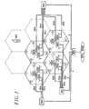
A la figure 1, on a représenté schématiquement les moyens essentiels d'un système de radiocommunication cellulaire selon l'art antérieur. In Figure 1, there is shown schematically the essential means of a radiocommunication system cell according to the prior art.
Trois BTS, dont les secteurs S1, S2 et S3 sont adjacents, sont regroupées sur un même site appelé base, et sont reliées respectivement à trois antennes directives orientées selon des directions à 120° l'une de l'autre. Ces trois secteurs forment une cellule C1. De même trois autres cellules C2, C3 et C4 sont formées chacune de trois secteurs couvrant chacun un angle de 120°, respectivement S4-S6, S7-S9, et S10-S12. On parle de cellules tri-sectorielles. A centre de chaque cellule se trouve une base abritant les BTS des trois secteurs de la cellule.Three BTS, whose sectors S1, S2 and S3 are adjacent, are grouped on the same site called base, and are connected respectively to three antennas directives oriented in directions at 120 ° one the other. These three sectors form a C1 cell. Similarly, three other cells C2, C3 and C4 are formed each of three sectors each covering an angle of 120 °, respectively S4-S6, S7-S9, and S10-S12. We are talking tri-sectoral cells. At the center of each cell is a base housing the BTS of the three cell sectors.
Une cellule est communément représentée de façon stylisée par un hexagone, ainsi qu'on peut le voir à la figure 1.A cell is commonly represented in a way stylized by a hexagon, as we can see at the figure 1.
L'aire géographique couverte par le système de radiocommunication est donc segmentée en un réseau de cellules tri-sectorielles, avec un plan d'attribution des fréquences constitué par un motif de base à quatre cellules et douze couleurs reproduit autant de fois que nécessaire, par abus de langage, les termes "secteur" et "cellule" seront indistinctement utilisés dans la suite pour désigner une zone de BTS.The geographic area covered by the radiocommunication is therefore segmented into a network of tri-sectoral units, with an allocation plan frequencies consisting of a basic pattern to four cells and twelve colors reproduced as many times as necessary, by abuse of language, the terms "sector" and "cell" will be used indiscriminately in the continued to designate a BTS area.
Une BTS donnée utilise donc les fréquences d'une seule et unique couleur pour les communications avec les mobiles présents dans la cellule à laquelle elle est associée. Les BTS comprennent donc autant de TRX qu'il y a de porteuses dans la couleur. Dans l'exemple ci-dessus, les BTS comprennent cinq TRX.A given BTS therefore uses the frequencies of a single color for communications with the mobiles present in the cell to which it is associated. BTS therefore include as many TRX that there are carriers in the color. In the example above, the BTS include five TRX.
En outre, l'axe des temps est divisé en intervalles de temps réguliers (Time Slots, en anglais), ci-après appelés IT, dont la durée est égale à 0,577 ms. Huit tels intervalles consécutifs forment une trame. Une trame dure donc 4,6 ms. Au sein d'une trame, les IT sont repérés par un numéro de zéro à sept. La suite récurrente des IT portant le même numéro constitue un canal physique pour la transmission de données ou de la parole. En fait, seuls sept IT par trame sont disponibles pour la transmission des données utiles. C'est donc sept canaux physiques qui sont disponibles par porteuse.In addition, the time axis is divided into intervals Time Slots, below called IT, whose duration is equal to 0.577 ms. Eight such consecutive intervals form a frame. A frame therefore lasts 4.6 ms. Within a frame, IT are identified by a number from zero to seven. recurrent IT with the same number constitutes a physical channel for data transmission or the speech. In fact, only seven IT per frame are available for the transmission of useful data. So seven physical channels are available per carrier.
Bien évidemment, cette division de l'axe des temps en intervalles s'applique aussi bien à la voie montante qu'à la voie descendante. Cependant la numérotation des IT pour la voie montante et la numérotation des IT pour la voie descendante sont décalées de trois unités. De la sorte, on s'assure qu'une station mobile ne peut émettre et recevoir en même temps.Obviously, this division of the time axis in intervals applies equally to the uplink than downlink. However the numbering of IT for uplink and IT numbering for the downlink are offset by three units. Of this way, we make sure that a mobile station cannot send and receive at the same time.
On constate ainsi un double entrelacement temporel et fréquentiel des canaux physiques pour la voie montante et des canaux physiques associés pour la voie descendante.There is thus a double temporal interlacing and frequency of physical channels for the channel upstream and associated physical channels for the channel descending.
De plus, la plupart des systèmes de radiocommunication GSM 900 utilisent la possibilité, prévue par la norme GSM 05-05, d'un saut de fréquence lent. Comme on le sait, cette fonctionnalité consiste à modifier de façon périodique (à chaque trame, soit toutes les 4,6 ms) l'attribution des couleurs aux différents secteurs du motif de base du réseau mobile. Ce saut de fréquence permet de répartir entre plusieurs canaux physiques l'effet d'un éventuel brouilleur qui perturberait une fréquence déterminée. Cette répartition se traduit par une linéarisation du rapport signal/bruit des différents canaux physiques et, par conséquent, par une amélioration de la qualité globale des radiocommunications.In addition, most GSM 900 radio communication use the possibility, provided by GSM 05-05 standard, frequency hopping slow. As we know, this functionality consists of modify periodically (with each frame, either every 4.6 ms) assigning colors to different sectors of the basic pattern of the mobile network. This frequency hopping allows distribution among several physical channels the effect of a possible jammer which would disrupt a specific frequency. This distribution results in a linearization of the report signal / noise of the different physical channels and, for example therefore, by improving the overall quality radio communications.
Dans chaque IT, on émet un train de 148 bits comprenant 114 bits d'informations utiles. Les bits restant sont des bits de service, notamment de signalisation et de synchronisation. Les bits de service comprennent notamment une séquence de 26 bits disposée en milieu de train, dite "séquence d'apprentissage", choisie pour ses bonnes propriétés d'autocorrélation. Cette séquence a pour fonction de permettre la synchronisation du canal physique malgré les phénomènes de trajets multiples inhérente à toute propagation radioélectrique.In each IT, we send a 148-bit train comprising 114 bits of useful information. Bits remaining are service bits, including signaling and synchronization. The bits of service include a 26 bit sequence arranged in the middle of the train, called "sequence learning ", chosen for its good properties autocorrelation. This sequence has the function of allow synchronization of the physical channel despite the multipath phenomena inherent in any radio propagation.
Différents types de canaux logiques sont multiplexés sur les canaux physiques. En effet, ces canaux logiques sont de deux types: d'une part des canaux de trafic (Trafic Channel, en anglais), ci-après appelés canaux TCH, et d'autre part des canaux de contrôle ou de signalisation (Control Channel, en anglais), ci-après appelés canaux CCH.Different types of logical channels are multiplexed on the physical channels. Indeed, these Logical channels are of two types: on the one hand Traffic Channels, below called TCH channels, and on the other hand control or signaling (Control Channel, in English), hereinafter called CCH channels.
Les premiers servent à la transmission de la parole ou de données produites par les usagers (les porteuses qui supportent les canaux TCH sont parfois appelées porteuses de conversation ou porteuses de trafic).The former are used for speech transmission or data produced by users (carriers which support TCH channels are sometimes called conversation carriers or traffic carriers).
Les seconds servent à la transmission d'informations nécessaires à la gestion du système. Notamment, les canaux CCH comprennent un canal diffusé (Broadcast Control Channel, en anglais), ci-après canal BCCH, qui fournit aux stations mobiles des informations relatives à la cellule dans laquelle elles se trouvent ainsi qu'aux cellules voisines. Le canal BCCH est un canal dans le sens réseau fixe vers réseau mobile. La porteuse qui supporte ce canal, dite ci-après "porteuse FBCCH" ou "porteuse balise", est émise à fréquence constante et sans régulation de niveau (en fait, elle est émise à la puissance maximum disponible).The second are used to transmit information necessary for the management of the system. In particular, the CCH channels include a broadcast channel (Broadcast Control Channel, in English), hereinafter the BCCH channel, which provides mobile stations with information relating to the cell in which they are located as well as to neighboring cells. The BCCH channel is a channel in the fixed network to mobile network direction. The carrier which supports this channel, hereinafter called "F BCCH carrier" or "beacon carrier", is transmitted at constant frequency and without level regulation (in fact, it is transmitted at the maximum power available).
Une porteuse FBCCH est associée à chaque secteur du motif de base. Un réseau mobile à motif de base à n secteurs nécessite donc au moins n porteuses FBCCH. De plus, les porteuses FBCCH ne sont pas soumises au saut lent de fréquence.A carrier F BCCH is associated with each sector of the basic pattern. A basic pattern mobile network with n sectors therefore requires at least n carriers F BCCH . In addition, the F BCCH carriers are not subject to the slow frequency hopping.
Chaque station mobile comporte des moyens pour mesurer le niveau de toutes les porteuses FBCCH qu'il lui est imposé de mesurer, à savoir la porteuse FBCCH associée à la cellule dans laquelle il se trouve, et les porteuses FBCCH associées aux cellules adjacentes à cette cellule. Les stations mobiles comportent aussi des moyens pour envoyer un rapport de mesure après calcul d'une moyenne sur un certain nombre de mesures, ce rapport incluant des informations sur la qualité des informations reçues en vue de permettre le basculement intercellulaire (hand-over, en anglais) nécessité par la nature mobile des usagers. La qualité des informations reçues est déterminée par le calcul d'un taux d'erreur.Each mobile station includes means for measuring the level of all the F BCCH carriers which it is obliged to measure, namely the F BCCH carrier associated with the cell in which it is located, and the F BCCH carriers associated with the adjacent cells. to this cell. The mobile stations also include means for sending a measurement report after calculating an average over a certain number of measurements, this report including information on the quality of the information received with a view to enabling intercellular switching (hand-over, in English) required by the mobile nature of users. The quality of the information received is determined by calculating an error rate.
En outre, les canaux CCH comprennent un canal d'accès aléatoire (Random Access Control Channel, en anglais), ci-après canal RACH. Le canal RACH est un canal dans le sens réseau mobile vers réseau fixe. La porteuse qui supporte ce canal, dite ci-après "porteuse FRACH", a une fréquence fRACH décalée par rapport à la fréquence fBCCH de la porteuse FBCCH d'un écart déterminé dont la valeur est celle de l'écart duplex mentionné ci-dessus, c'est à dire 45 MHz pour un système conforme à la norme GSM 900. Plus précisément la fréquence de la porteuse FRACH est inférieure de 45 MHz à la fréquence de la porteuse FBCCH (fRACH=fBCCH-45 MHz). Dit autrement, la porteuse FRACH est en dessous de la porteuse FBCCH et l'écart entre les deux est constant. Il vaut 45 MHz pour un système conforme à la norme GSM 900 et 95 MHz pour un système conforme à la norme DCS 1800. In addition, CCH channels include a Random Access Control Channel, hereinafter RACH channel. The RACH channel is a channel in the mobile network to fixed network direction. The carrier which supports this channel, hereinafter called "carrier F RACH ", has a frequency f RACH offset with respect to the frequency f BCCH of the carrier F BCCH by a determined deviation whose value is that of the duplex deviation mentioned above, ie 45 MHz for a system conforming to the GSM 900 standard. More precisely, the frequency of the carrier F RACH is 45 MHz lower than the frequency of the carrier F BCCH (f RACH = f BCCH -45 MHz). In other words, the carrier F RACH is below the carrier F BCCH and the difference between the two is constant. It is worth 45 MHz for a system compliant with the GSM 900 standard and 95 MHz for a system compliant with the DCS 1800 standard.
En outre le canal physique supportant le canal RACH est décalé de trois intervalles de temps ("Time Slots") dans le sens retard, par rapport au canal physique supportant le canal BCCH.In addition the physical channel supporting the RACH channel is offset by three time slots ("Time Slots") in the delay direction, relative to the physical channel supporting the BCCH channel.
La porteuse FRACH est émise au maximum de puissance disponible, notamment à la mise en route de la station mobile. En effet, la station mobile comporte des moyens pour mesurer le niveau des porteuses FBCCH qu'il peut recevoir et pour rechercher la porteuse dont le niveau est maximum, ainsi que des moyens pour émettre un message d'acquittement sur le canal RACH duplex associé au canal BCCH correspondant à cette porteuse. Par l'émission de ce message d'acquittement, la station mobile effectue une demande d'allocation de ressources, en vue de l'établissement d'une communication.The carrier F RACH is transmitted at the maximum available power, in particular when the mobile station is started up. In fact, the mobile station includes means for measuring the level of the F BCCH carriers it can receive and for searching for the carrier whose level is maximum, as well as means for transmitting an acknowledgment message on the associated duplex RACH channel. to the BCCH channel corresponding to this carrier. By sending this acknowledgment message, the mobile station makes a request for allocation of resources, with a view to establishing a call.
L'invention concerne un récepteur de système de radiocommunication cellulaire, tel que le système décrit ci-dessus. Plus particulièrement, le récepteur est un récepteur large bande pour un répéteur multiporteuse, placé en tête des moyens de communication fixes dans la chaíne de transmission montante (réseau mobile vers réseau fixe).A receiver system receiver is provided. cellular radio, such as the system described above. More specifically, the receiver is a broadband receiver for a repeater multicarrier, placed at the head of the means of fixed communication in the transmission chain up (mobile network to fixed network).
Un tel récepteur est donc placé dans le système en amont des BTS, le terme amont devant ici être compris en considérant le sens réseau mobile vers réseau fixe.Such a receiver is therefore placed in the system in upstream of BTS, the term upstream must be understood here considering the direction mobile network to fixed network.
Un signal multifréquence dont le spectre comporte des porteuses GSM, notamment une porteuse FRACH, est transmis dans le sens réseau mobile vers réseau fixe entre une station mobile et un site d'émission/réception où il est reçu par le récepteur au moyen d'une antenne.A multifrequency signal whose spectrum includes GSM carriers, in particular an F RACH carrier, is transmitted in the mobile network to fixed network direction between a mobile station and a transmission / reception site where it is received by the receiver by means of an antenna.
Il est ensuite délivré en entrée d'une BTS, soit directement si la BTS et les moyens d'émission/réception sont sur le même site, soit après transmission sur une liaison si le site d'installation de la BTS et le site d'émission/réception sont éloignés.It is then issued as a BTS entry, i.e. directly if the BTS and the means transmission / reception are on the same site, either after transmission over a link if the installation site of the BTS and the transmission / reception site are distant.
Ce dernier cas se rencontre notamment dans une configuration microcellulaire. Dans une telle configuration, les signaux multifréquence émis par les stations mobiles sont reçus par des boítiers d'émission/réception disposés à quelques mètres au dessus du sol (on parle de configuration "au dessous des toits") qui contiennent un récepteur. En milieu urbain, la zone de couverture d'un tel boítier d'émission/réception correspond classiquement à un groupe de rues appelé "microcellule". Plusieurs microcellules dépendent d'une même BTS et la liaison entre la BTS et les boítiers d'émission/réception est réalisée sur fibre optique ou câble coaxial, voire même par faisceau hertzien, moyennant transposition de fréquence appropriée à chaque extrémité.The latter case is encountered in particular in a microcellular configuration. In such configuration, the multifrequency signals emitted by the mobile stations are received by boxes transmission / reception devices located a few meters away above ground (we speak of configuration "below roofs ") that contain a receiver. In the middle urban, the coverage area of such a housing transmission / reception conventionally corresponds to a group of streets called "microcell". Many microcells depend on the same BTS and the binding between the BTS and the transmitting / receiving boxes is performed on optical fiber or coaxial cable, or even by radio link, by transposition of appropriate frequency at each end.
On a dit ci-dessus que la porteuse FRACH est émise par les stations mobiles à la puissance maximum disponible, c'est à dire à une puissance de l'ordre de 1 Watt pour un téléphone portatif de classe 5. La porteuse FRACH présente donc un niveau bien supérieur à celui des autres porteuses (porteuses de trafic).It has been said above that the carrier F RACH is transmitted by the mobile stations at the maximum power available, that is to say at a power of the order of 1 Watt for a portable telephone of class 5. The carrier F RACH therefore presents a level much higher than that of other carriers (carriers of traffic).
Or, si la distance qui sépare la station mobile du récepteur est faible, notamment, dans la cas d'une configuration microcellulaire, si l'usager se trouve juste en dessous d'un boítier d'émission/réception, cette porteuse est susceptible de saturer le récepteur et/ou d'autres équipements de la chaíne de transmission montante.However, if the distance between the mobile station and receiver is weak, in particular, in the case of a microcellular configuration, if the user is located just below a transmission / reception unit, this carrier is likely to saturate the receiver and / or other equipment in the transmission chain rising.
Dans les cas les plus défavorables, le niveau de la porteuse FRACH peut être supérieur de 20 à 40 dB au niveau des autres porteuses du signal multifréquence. In the most unfavorable cases, the level of the F RACH carrier can be 20 to 40 dB higher than the other carriers of the multifrequency signal.
Certains équipements comportant des moyens de réglage de leur sensibilité, par exemple des dispositifs de contrôle automatique de gain, la sensibilité de ces équipements peut alors être brutalement réduite du fait de l'apparition de la porteuse FRACH dans le spectre, en sorte que la modulation des autres porteuses par des signaux d'informations et/ou de parole provenant d'autres stations mobiles peut ne pas être détectée de façon correcte. De manière imagée, ou peut dire que la chaíne de transmission montante est "éblouie" par la porteuse FRACH.Certain equipment comprising means for adjusting their sensitivity, for example automatic gain control devices, the sensitivity of this equipment can then be suddenly reduced due to the appearance of the carrier F RACH in the spectrum, so that the modulation of other carriers by information and / or speech signals from other mobile stations may not be detected correctly. Imaginatively, or can say that the uplink transmission chain is "dazzled" by the carrier F RACH .
La présente invention vise à proposer des moyens pour résoudre ce problème.The present invention aims to propose means to resolve this problem.
A cet effet, l'invention propose un récepteur de système de radiocommunication cellulaire, notamment un système conforme à la norme GSM 900 ou à la norme DCS 1800 qui comporte des premiers moyens pour transmettre, dans le sens réseau fixe vers réseau mobile, un signal multifréquence ayant un spectre qui comprend une porteuse balise dont la fréquence est fixe, et des seconds moyens pour transmettre, dans le sens réseau mobile vers réseau fixe, un signal multifréquence ayant un spectre qui comprend une porteuse d'accès aléatoire dont la fréquence est décalée d'un écart déterminé par rapport à la fréquence de ladite porteuse balise.To this end, the invention provides a receiver for cellular radio system including a GSM 900 or DCS standard compliant system 1800 which includes the first means to transmit, in the fixed network to mobile network direction, a signal multifrequency having a spectrum which includes a beacon carrier whose frequency is fixed, and second means for transmitting, in the network direction mobile to fixed network, a multi-frequency signal having a spectrum which includes a random access carrier whose frequency is offset by a difference determined by with respect to the frequency of said beacon carrier.
Le récepteur selon l'invention comporte un dispositif d'atténuation sélective du niveau de la seule porteuse d'accès aléatoire lorsque celui-ci est supérieur à un seuil déterminé.The receiver according to the invention comprises a selective level reduction device only carrier of random access when this is greater than a determined threshold.
Ainsi, lorsque la station mobile qui émet un message d'acquittement sur le canal RACH est physiquement très proche du récepteur, le niveau de la porteuse RACH est atténué mais non celui des autres porteuses du spectre.So when the mobile station that transmits a acknowledgment message on the RACH channel is physically very close to the receiver, the level of carrier RACH is attenuated but not that of others carrying the spectrum.
Selon une caractéristique avantageuse de l'invention, le dispositif d'atténuation sélective est un dispositif interférométrique assurant l'atténuation par couplage, en opposition de phase et à niveau requis, d'un signal d'atténuation à la fréquence de la porteuse d'accès aléatoire. Un tel dispositif présente de bonnes propriétés de linéarité et permet donc de ne pas fortement déformer le reste du spectre du signal multifréquence.According to an advantageous characteristic of the invention, the selective attenuation device is an interferometric device ensuring attenuation by coupling, in phase opposition and at level required, an attenuation signal at the frequency of the carrier of random access. Such a device presents good linearity properties and therefore allows not strongly distort the rest of the signal spectrum multifrequency.
Selon une autre caractéristique avantageuse de l'invention, le dispositif d'atténuation sélective comporte des moyens de filtrage à bande étroite fonctionnant à une fréquence intermédiaire basse ou à fréquence intermédiaire nulle, ainsi que des premiers moyens de transposition pour assurer la transposition du signal multifréquence à cette fréquence intermédiaire avant filtrage, et des seconds moyens de transposition pour rétablir le signal multifréquence dans sa bande d'origine après filtrage.According to another advantageous characteristic of the invention, the selective attenuation device includes narrow band filtering means operating at a low intermediate frequency or at zero intermediate frequency, as well as first means of transposition to ensure transposition of the multi-frequency signal at this frequency intermediate before filtering, and second means of transposition to restore the multi-frequency signal in its original band after filtering.
Au sens de la caractéristique qui précède, une fréquence intermédiaire basse est une fréquence de valeur faible par rapport aux valeurs des fréquences GSM qui sont comprises entre 900 et 1000 MHz. Par exemple, une fréquence basse est de l'ordre de quelques dizaines de mégahertz au maximum.Within the meaning of the above characteristic, a low intermediate frequency is a frequency of low value compared to frequency values GSM which are between 900 and 1000 MHz. Through example, a low frequency is around a few tens of megahertz at most.
Cette fréquence intermédiaire sera fixe quelle que soit la fréquence des porteuses FBCCH et FRACH, par changement de la fréquence de l'oscillateur local de transposition, asservi à la fréquence de la porteuse FBCCH.This intermediate frequency will be fixed whatever the frequency of the carriers F BCCH and F RACH , by changing the frequency of the local transposition oscillator, subject to the frequency of the carrier F BCCH .
La transposition du signal multifréquence à une fréquence intermédiaire basse, avant filtrage, permet d'utiliser un filtre à bande étroite et à forte réjection qui est plus simple à réaliser et donc plus économique qu'un filtre présentant les mêmes propriétés mais devant fonctionner dans la bande comprise entre 900 et 1000 MHz.Transposing the multi-frequency signal to a low intermediate frequency, before filtering, allows use a narrow band filter with high rejection which is simpler to carry out and therefore more economical than a filter with the same properties but having to operate in the band between 900 and 1000 MHz.
L'invention propose également un système de radiocommunication cellulaire incorporant un récepteur tel que celui décrit ci-dessus.The invention also provides a system for cellular radio communication incorporating a receiver like the one described above.
D'autres caractéristiques et avantages de la présente invention apparaítront encore à la lecture de la description qui va suivre. Celle-ci est purement illustrative et doit être lue en regard des dessins annexés sur lesquels on a représenté:
- à la figure 1, déjà analysée: les moyens essentiels d'un système de radiocommunication cellulaire;
- à la figure 2a et à la figure 2b: respectivement le spectre d'un signal multifréquence émis dans le sens réseau fixe vers réseau mobile et le spectre du signal duplex associé;
- à la figure 3: le schéma d'un premier mode de réalisation d'un récepteur selon l'invention;
- à la figure 4: un schéma d'un second mode de réalisation d'un récepteur selon l'invention.
- in FIG. 1, already analyzed: the essential means of a cellular radiocommunication system;
- in FIG. 2a and in FIG. 2b: respectively the spectrum of a multi-frequency signal transmitted in the fixed network to mobile network direction and the spectrum of the associated duplex signal;
- in FIG. 3: the diagram of a first embodiment of a receiver according to the invention;
- in Figure 4: a diagram of a second embodiment of a receiver according to the invention.
Comme il a été dit en introduction, une BTS émet (dans le sens réseau fixe vers réseau mobile) un signal à destination des stations mobiles présentes dans la cellule couverte, qui est un signal multifréquence c'est-à-dire dont le spectre comprend plusieurs fréquences de porteuses dans la bande utile.As mentioned in the introduction, a BTS broadcasts (in the fixed network to mobile network direction) a signal to mobile stations in the covered cell, which is a multi-frequency signal that is to say whose spectrum includes several carrier frequencies in the useful band.
Dans la description qui va suivre, on considère l'exemple d'un signal occupant une bande utile dont la largeur est de l'ordre de 6 ou 7 MHz. Les porteuses sont des porteuses GSM. In the description which follows, we consider the example of a signal occupying a useful band whose width is around 6 or 7 MHz. The carriers are GSM carriers.
Parmi ces porteuses, on dénombre des porteuses de conversation ou de trafic (ou porteuses TCH), éventuellement soumises aux sauts de fréquence toutes les 4,6 ms et émises à des niveaux variables d'un intervalle de temps ("Time Slot") au suivant. Ces porteuse peuvent être modulées par des signaux d'information et/ou de parole.Among these carriers, there are carriers of conversation or traffic (or TCH carriers), possibly subject to frequency hopping all the 4.6 ms and transmitted at varying levels of a time slot ("Time Slot") to the next. These carrier can be modulated by signals information and / or speech.
On dénombre également une porteuse balise (ou porteuse BCCH) non soumise aux sauts de fréquence et émise à un niveau constant. Cette porteuse est modulée par des signaux de signalisation et/ou de synchronisation.There is also a tag carrier (or carrier BCCH) not subject to frequency hopping and issued at a constant level. This carrier is modulated by signaling signals and / or synchronization.
Plus particulièrement on considère un signal pouvant contenir sept porteuses réparties sur trente deux positions possibles dans une bande comprise entre 935,2 MHz et 941,8 MHz. Les positions possibles dans cette bande sont espacées d'un pas de 200 kHz.More particularly we consider a signal can contain seven carriers spread over thirty two possible positions in a band between 935.2 MHz and 941.8 MHz. Possible positions in this band are spaced by a step of 200 kHz.
A la figure 2a, on a représenté le spectre d'un tel signal à un instant donné. Il comprend une porteuse balise, notée FBCCH à la figure, située à une position parmi huit positions possibles sur l'axe des fréquences. Ces huit positions possibles se situent de préférence en milieu de la bande utile. L'avantage de cette disposition sera exposé plus loin.In FIG. 2a, the spectrum of such a signal is shown at a given time. It includes a beacon carrier, denoted F BCCH in the figure, located at one position among eight possible positions on the frequency axis. These eight possible positions are preferably located in the middle of the useful band. The advantage of this arrangement will be explained later.
La position occupée par la porteuse FBCCH parmi les huit positions possibles ne varie pas au cours du temps, puisque cette porteuse n'est pas soumise aux sauts de fréquence. Cette position dépend de la cellule à laquelle correspond la BTS considérée au sein du motif de base du réseau cellulaire.The position occupied by the carrier F BCCH among the eight possible positions does not vary over time, since this carrier is not subject to frequency hopping. This position depends on the cell to which the BTS considered corresponds within the basic pattern of the cellular network.
Le spectre du signal comporte en outre trois porteuses de trafic (notées FTCH1, FTCH2, FTCH3) pouvant respectivement occuper trois positions distinctes parmi douze positions possibles dans la partie basse de la bande utile.The signal spectrum also comprises three traffic carriers (denoted F TCH1 , F TCH2 , F TCH3 ) which can respectively occupy three distinct positions among twelve possible positions in the lower part of the useful band.
Le spectre comporte enfin trois autres porteuses de trafic (notées FTCH4, FTCH5, FTCH6) pouvant respectivement occuper trois positions distinctes parmi les douze positions possibles dans la partie haute de la bande utile. Ces six porteuses TCH occupent une position variable dans le temps, en fonction du saut de fréquence.Finally, the spectrum includes three other traffic carriers (denoted F TCH4 , F TCH5 , F TCH6 ) which can respectively occupy three distinct positions among the twelve possible positions in the upper part of the useful band. These six TCH carriers occupy a variable position over time, as a function of the frequency hopping.
La combinaison des positions occupées par les porteuses est déterminée par l'opérateur et résulte des choix impliqués par la planification des fréquences disponibles. Une combinaison de porteuses telle que celle représentée à la figure 2a constitue une couleur au sens indiqué en introduction.The combination of positions occupied by carriers is determined by the operator and results from choices involved in frequency planning available. A combination of carriers such as that shown in Figure 2a is a color in the sense indicated in the introduction.
On notera que dans chaque couleur, on ne trouve jamais deux porteuses adjacentes c'est-à-dire espacées de 200 kHz seulement. Dit autrement, deux porteuses appartenant à une même couleur, sont espacées de 400 kHz au moins.Note that in each color, there is no never two adjacent carriers that is to say spaced 200 kHz only. In other words, two carriers belonging to the same color, are spaced 400 kHz at least.
A la figure 2b, on a représenté le spectre d'un signal émis, lors de sa mise en fonctionnement, par une station mobile présente dans la zone couverte par la même BTS.In FIG. 2b, the spectrum of a signal emitted, when it is put into operation, by a mobile station present in the area covered by the even BTS.
La bande utile de ce signal est décalée, vers les fréquences inférieures, de 45 MHz (écart duplex pour un système GSM 900) par rapport à la bande utile du signal de la figure 2a.The useful band of this signal is shifted, towards the lower frequencies, 45 MHz (duplex deviation for a GSM 900 system) relative to the useful band of the signal of Figure 2a.
Le spectre de la figure 2b comporte une porteuse FRACH, qui est décalée, vers les fréquences inférieures, de 45 MHz par rapport à la porteuse FBBCH comprise dans le spectre du signal de la figure 2a. On notera que la porteuse FRACH se trouve donc avantageusement en milieu de la bande utile du spectre de la figure 2b. Celle-ci est comprise entre 890,2 MHz et 896,8 MHz. Elle est modulée par un signal de signalisation et de demande d'allocation de ressource émis par une station mobile avant l'établissement d'une communication.The spectrum of FIG. 2b comprises a carrier F RACH , which is shifted, towards the lower frequencies, by 45 MHz with respect to the carrier F BBCH included in the spectrum of the signal of FIG. 2a. It will be noted that the carrier F RACH is therefore advantageously in the middle of the useful band of the spectrum of FIG. 2b. This ranges from 890.2 MHz to 896.8 MHz. It is modulated by a signal for signaling and requesting resource allocation sent by a mobile station before the establishment of a call.
Le spectre comporte en outre des porteuses de trafic notées FTCH1', FTCH2', FTCH3', FTCH4', FTCH5', et FTCH6' qui sont respectivement décalées de 45 MHz vers les fréquences inférieures, par rapport, respectivement, aux porteuses FTCH1, FTCH2, FTCH3, FTCH4, FTCH5, et FTCH6 du signal de la figure 2a. Ces porteuses peuvent être modulées par des signaux d'information et/ou de parole émis par les stations mobiles.The spectrum also comprises traffic carriers denoted F TCH1 ', F TCH2 ', F TCH3 ', F TCH4 ', F TCH5 ', and F TCH6 ' which are respectively offset by 45 MHz towards the lower frequencies, with respect to, respectively , to the carriers F TCH1 , F TCH2 , F TCH3 , F TCH4 , F TCH5 , and F TCH6 of the signal of FIG. 2a. These carriers can be modulated by information and / or speech signals transmitted by the mobile stations.
Ainsi qu'on peut le voir représenté schématiquement à la figure 2b par la longueur des flèches qui symbolisent les porteuses du spectre, la porteuse FRACH peut avoir un niveau très supérieur (de 20 à 40 dB) à celui des autres porteuses.As can be seen represented diagrammatically in FIG. 2b by the length of the arrows which symbolize the carriers of the spectrum, the carrier F RACH can have a much higher level (from 20 to 40 dB) than that of the other carriers.
Le récepteur selon l'invention comporte un dispositif d'atténuation du niveau de la seule porteuse FRACH lorsque celui-ci est supérieur à un seuil déterminé Vo. Dans la suite, on parlera parfois d'un dispositif d'atténuation sélective car il n'a d'effets que sur la fréquence fRACH de la porteuse FRACH, sans perturber les autres fréquences de porteuses du spectre.The receiver according to the invention comprises a device for attenuating the level of the single carrier F RACH when the latter is greater than a determined threshold Vo. In the following, we will sometimes speak of a selective attenuation device because it has effects only on the frequency f RACH of the carrier F RACH , without disturbing the other frequencies of carriers of the spectrum.
Plus précisément, le récepteur comporte :
- des moyens de détection du niveau de la porteuse FRACH;
- une première voie qui est active en l'absence de dépassement du seuil Vo par le niveau de la porteuse FRACH;
- une seconde voie, comportant le dispositif d'atténuation sélective, qui est active dans le cas contraire;
- et des moyens de sélection pour sélectionner l'une ou l'autre voie en fonction du niveau de la porteuse FRACH.
- means for detecting the level of the carrier F RACH ;
- a first channel which is active in the absence of the Vo threshold being exceeded by the level of the carrier F RACH ;
- a second channel, comprising the selective attenuation device, which is active in the opposite case;
- and selection means for selecting one or the other channel as a function of the level of the carrier F RACH .
La figure 3 est un schéma d'un premier mode de réalisation d'un récepteur selon l'invention.Figure 3 is a diagram of a first mode of realization of a receiver according to the invention.
Le récepteur comporte une antenne A pour recevoir
un signal multifréquence émis par les stations mobiles
se trouvant dans la zone couverte par le récepteur.
L'antenne est suivie d'une filtre passe-bande F1 centré
sur la bande utile de ce signal, à savoir la bande
comprise entre 890,2 et 896,8 MHz dans l'exemple. La
sortie du filtre F1 est reliée, par l'intermédiaire
d'une ligne à retard 20, à l'entrée commune d'un
commutateur radiofréquence 5a, à une entrée et deux
sorties.The receiver has an antenna A to receive
a multi-frequency signal from mobile stations
located in the area covered by the receiver.
The antenna is followed by a centered F1 bandpass filter
on the useful band of this signal, namely the band
between 890.2 and 896.8 MHz in the example. The
filter output F1 is connected, via
a
La sortie S du récepteur est prise sur la sortie
commune d'un second commutateur radiofréquence 5b, à
deux entrées et une sortie.The output S of the receiver is taken on the output
common of a second
La première voie précitée du récepteur relie une
première sortie du commutateur 5a à une première entrée
du commutateur 5b. De même, la seconde voie précitée
relie la seconde sortie du commutateur 5a à la seconde
entrée du commutateur 5b.The first aforementioned channel of the receiver connects a
first output of
Pour un premier couple de positions des
commutateurs 5a à 5b, le signal reçu par l'antenne A,
filtré par le filtre F1, et retardé par la ligne à
retard 20, est transmis directement en sortie S du
récepteur par la première voie.For a first couple of positions of
Pour un second couple de positions des commutateurs
5a et 5b, ce même signal est transmis à la sortie S du
récepteur par la seconde voie comprenant le dispositif
d'atténuation sélective du niveau de la porteuse FRACH.For a second pair of positions of the
Comme on l'aura compris, la position des
commutateurs 5a et 5b est commandée par les moyens de
sélection précités. A la figure 3, ceux-ci portent la
référence SEL. Ils génèrent des signaux de commande CSA
et CSB de la position des commutateurs respectivement
5a et 5b.As will be understood, the position of
En d'autres termes, la fonction des moyens de sélection SEL est de comparer le niveau de la porteuse FRACH au seuil Vo et de générer les signaux CSA et CSB en conséquence. Par niveau de la porteuse, on entend par exemple le module du rayon vecteur de cette porteuse (exprimé en volts).In other words, the function of the selection means SEL is to compare the level of the carrier F RACH to the threshold Vo and to generate the signals CSA and CSB accordingly. By carrier level is meant, for example, the modulus of the vector radius of this carrier (expressed in volts).
Les moyens de détection du niveau de la porteuse
FRACH comprennent en série un coupleur 2 disposé entre
le filtre F1 et la ligne à retard 20 , un filtre passe-bande
3 centré sur la bande utile du signal
multifréquence, ainsi qu'un détecteur 1 relié aux
moyens de sélection SEL.The means for detecting the level of the carrier F RACH comprises in series a
Le coupleur 2 permet de prélever une partie de la
puissance du signal multifréquence reçu.The
La caractéristique mentionnée plus haut, selon
laquelle la porteuse FRACH se trouve dans le milieu de
la bande utile du signal multifréquence reçu, permet de
simplifier la conception du filtre 3.The characteristic mentioned above, according to which the carrier F RACH is in the middle of the useful band of the multifrequency signal received, makes it possible to simplify the design of the
Dans le mode de réalisation représenté à la figure 3, le détecteur 1 réalise une détection directe du niveau de la porteuse FRACH.In the embodiment shown in FIG. 3, the detector 1 performs direct detection of the level of the carrier F RACH .
Le dispositif d'atténuation sélective compris dans la seconde voie du circuit du récepteur, est préférentiellement, mais non nécessairement, un dispositif interférométrique, c'est-à-dire assurant l'atténuation par interférométrie. Un tel dispositif réalise l'injection par couplage, dans le signal multifréquence, en opposition de phase et à niveau requis, d'un signal d'atténuation à la fréquence fRACH de la porteuse FRACH. Le récepteur comprend donc des moyens de filtrage et d'amplification de la porteuse FRACH permettant de générer ce signal d'atténuation.The selective attenuation device included in the second channel of the receiver circuit, is preferably, but not necessarily, an interferometric device, that is to say ensuring attenuation by interferometry. Such a device injects by coupling, into the multifrequency signal, in phase opposition and at the required level, an attenuation signal at the frequency f RACH of the carrier F RACH . The receiver therefore comprises means for filtering and amplifying the carrier F RACH making it possible to generate this attenuation signal.
La fréquence fRACH de la porteuse FRACH étant fonction de la cellule dans laquelle le récepteur est implanté, il faudrait en principe autant de tels moyens différents qu'il y a de cellules dans le motif de base du réseau cellulaire. En outre, en cas de modification du plan de fréquences, l'affectation des récepteurs à telle ou telle cellule devrait être modifiée. Ou alors, les moyens de génération du signal d'atténuation à la fréquence fRACH de la porteuse FRACH devraient être modifiés. On va voir que, grâce à l'invention, les problèmes ci-dessus sont en fait éliminés.The frequency f RACH of the carrier F RACH being a function of the cell in which the receiver is implanted, it would in principle be necessary as many such different means as there are cells in the basic pattern of the cellular network. In addition, in the event of a change in the frequency plan, the allocation of receivers to a particular cell should be changed. Alternatively, the means for generating the attenuation signal at the frequency f RACH of the carrier F RACH should be modified. We will see that, thanks to the invention, the above problems are in fact eliminated.
En effet, selon une caractéristique avantageuse de l'invention, le signal d'atténuation à la fréquence fRACH est généré en fonction de la fréquence fBCCH de la porteuse FBCCH de manière simple et efficace. On connaít en effet des moyens de régénération de la porteuse FBCCH et on sait, de façon certaine, que la porteuse FRACH se trouve 45 MHz en dessous de la porteuse FBCCH.Indeed, according to an advantageous characteristic of the invention, the attenuation signal at the frequency f RACH is generated as a function of the frequency f BCCH of the carrier F BCCH in a simple and effective manner. We know in fact means of regeneration of the carrier F BCCH and we know, with certainty, that the carrier F RACH is 45 MHz below the carrier F BCCH .
Le récepteur selon l'invention comporte donc un
circuit 12 de régénération de la fréquence fBCCH de la
porteuse balise FBCCH.The receiver according to the invention therefore comprises a
De façon avantageuse, ce circuit 12 est un circuit
d'une station mobile du système conçu pour remplir
cette fonction. On sait en effet que les stations
mobiles du système de radiocommunication cellulaire
comprennent un tel circuit pour détecter en permanence
le niveau de la porteuse balise de la cellule dans
laquelle elles se trouvent ainsi d'ailleurs que le
niveau des porteuses balises des cellules adjacentes.Advantageously, this
Dans un exemple de réalisation particulièrement simple, une station mobile est tout simplement installée à demeure dans le récepteur pour y tenir le rôle de circuit de régénération de la fréquence fBCCH de la porteuse FBCCH.In a particularly simple embodiment, a mobile station is quite simply permanently installed in the receiver in order to fulfill the role of a circuit for regenerating the frequency f BCCH of the carrier F BCCH .
Le dispositif interférométrique représenté à la
figure 3 est une boucle d'interférence L, dont une
branche directe comprend une ligne à retard 22 en série
avec un atténuateur variable 18, et dont une branche
secondaire comprend des moyens de filtrage à bande
étroite permettant d'isoler la porteuse FRACH.The interferometric device shown in FIG. 3 is an interference loop L, a direct branch of which comprises a
La branche secondaire comprend un coupleur 25
disposé avant la ligne à retard 22 et un coupleur 26
disposé après l'atténuateur variable 18.The secondary branch includes a
Entre ces deux coupleurs 25 et 26, la branche secondaire comporte :
- des premiers moyens de transposition pour assurer la transposition du signal à une fréquence intermédiaire;
- des moyens de filtrage à bande étroite fonctionnant à la fréquence intermédiaire;
- et des seconds moyens de transposition pour rétablir le signal dans sa bande d'origine après filtrage.
- first transposition means for transposing the signal at an intermediate frequency;
- narrow band filtering means operating at the intermediate frequency;
- and second transposition means to restore the signal to its original band after filtering.
Les premiers et les seconds moyens de transposition
comprennent chacun un modulateur 8a et 10a
respectivement. En outre, Ces premiers et ces seconds
moyens comprennent avantageusement un même et unique
oscillateur local 11 oscillant à une fréquence qui est
fonction de la fréquence fBCCH de la porteuse FBCCH
régénérée, de l'écart constant entre la fréquence de la
porteuse FBCCH et celle de la porteuse FRACH (écart
duplex, qui vaut 45 MHz), et de la fréquence
intermédiaire.The first and second transposition means each comprise a
Dans le mode de réalisation de la figure 3, la fréquence intermédiaire est basse par rapport aux fréquences des porteuses GSM contenues dans le signal multifréquence.In the embodiment of Figure 3, the intermediate frequency is low compared to GSM carrier frequencies contained in the signal multifrequency.
Dans un exemple, la fréquence intermédiaire vaut
10,7 MHz. L'oscillateur 11 est alors commandé par le
circuit de régénération 12 de la fréquence de la
porteuse FBCCH, de manière à osciller à la fréquence
fBCCH -45 MHz -10,7 MHz.In one example, the intermediate frequency is 10.7 MHz. The
Les moyens de filtrage comprennent un filtre passe-bande
9a à bande étroite, centré sur la fréquence
intermédiaire. La bande passante du filtre 9a vaut 200
KHz de manière à ne conserver que la porteuse FRACH
transposée à la fréquence intermédiaire.The filtering means comprise a
On comprend donc que les premiers moyens de transposition ont pour fonction de transposer le signal à filtrer à une fréquence intermédiaire à laquelle les moyens de filtrage sont plus faciles à réaliser. En effet dans le mode réalisation de la figure 3, la fréquence intermédiaire vaut 10,7 MHz et il est plus facile de réaliser un filtre passe-bande de 200 KHz de largeur à cette fréquence qu'à une fréquence GSM de l'ordre de 900 à 1000 MHz.We therefore understand that the first means of transposition have the function of transposing the signal to be filtered at an intermediate frequency at which the filtering means are easier to perform. In effect in the embodiment of Figure 3, the intermediate frequency is worth 10.7 MHz and it's more easy to make a 200 KHz bandpass filter width at this frequency than at a GSM frequency of around 900 to 1000 MHz.
Le signal en sortie des seconds moyens de
transposition 10a est filtré au moyen d'un filtre
passe-bande 14, puis il est déphasé au moyen notamment
du déphaseur variable 15 et amplifié de façon linéaire
au moyen d'un amplificateur 19, respectivement à la
phase requise (180°) au niveau requis (quelques
milliwatts) pour constituer le signal d'atténuation de
la boucle interférométrique. Il est ensuite réinjecté
dans la branche primaire, en opposition de phase, par
l'intermédiaire du coupleur 26.The signal at the output of the second means of
L'atténuation du niveau de la porteuse FRACH qui est ainsi obtenue est de l'ordre de 20 à 30 dB.The attenuation of the level of the carrier F RACH which is thus obtained is of the order of 20 to 30 dB.
En vue du réglage de la boucle L, des moyens
complémentaires sont en outre prévus dans le circuit du
récepteur pour commander l'atténuateur variable 13 et
le déphaseur variable 15.With a view to adjusting the loop L, means
are also planned in the circuit of
receiver for controlling the
Ces moyens comprennent un commutateur 6 à deux
entrées et une sortie, disposé dans la seconde voie du
circuit, entre le commutateur 5a et le coupleur 25.
Plus précisément, une première entrée du commutateur 6
est reliée à la seconde sortie du commutateur 5a, et la
sortie du commutateur 6 est reliée à l'entrée du
coupleur 25. Le seconde entrée du commutateur 6 est
reliée au circuit 12 de régénération de la porteuse
FBCCH pour recevoir un signal pilote à la fréquence
fRACH de la porteuse FRACH.These means comprise a
Dans une première position du commutateur 6,
l'entrée de la seconde voie du circuit est connectée à
la sortie du commutateur 5a qui délivre le signal
multifréquence reçu par l'antenne A et filtré par le
filtre F1.In a first position of
Dans une seconde position du commutateur 6,
l'entrée de la seconde voie du circuit est connectée à
une sortie du circuit de régénération 12 qui délivre le
signal pilote à la fréquence fRACH et à niveau connu et
constant. Ce signal est introduit à l'entrée de la
boucle L. Si celle-ci est bien réglée, le signal en
sortie de la boucle L doit avoir, à la fréquence fRACH,
un niveau quasiment nul. Dit autrement, le signal
pilote injecté en entrée de la boucle L doit
théoriquement avoir disparu en sortie de ladite boucle. In a second position of the
Le circuit comprend des moyens de mesure du niveau
résiduel du signal pilote en sortie de la boucle L. Ces
moyens sont des moyens de mesure du niveau du signal à
la fréquence fRACH en sortie de la boucle L. Ces moyens
comprennent un coupleur 27 disposé dans la seconde voie
du circuit, entre la sortie du coupleur 26 et la
seconde entrée du commutateur 5b, ainsi qu'un détecteur
16.The circuit comprises means for measuring the residual level of the pilot signal at the output of the loop L. These means are means for measuring the level of the signal at the frequency f RACH at the output of the loop L. These means comprise a
Dans le mode de réalisation décrit à la figure 3,
ce détecteur 16 réalise une détection directe du niveau
du signal à la fréquence fRACH de la porteuse FRACH.
L'atténuateur variable 13 ainsi que le déphaseur
variable 15 sont réglés en fonction de cette détection
par des moyens non représentés.In the embodiment described in FIG. 3, this
Cette mesure et ces réglages sont effectués pendant des phases de test réalisées en l'absence de porteuse FRACH de niveau supérieur à un seuil déterminé.This measurement and these adjustments are carried out during test phases carried out in the absence of an F RACH carrier of a level greater than a determined threshold.
De préférence, la première voie comporte une ligne
à retard 21 pour compenser le retard introduit par la
seconde voie du circuit lorsqu'elle est active. De la
sorte, le retard des signaux transmis est identique
quelle que soit la voie qui est active. On notera
l'effet de la ligne à retard 21 et celui de la ligne à
retard 22 doivent être pris en compte tous les deux
pour réaliser cet équilibre des retards. Les lignes à
retard 21 et 22 ont également pour fonction d'assurer
la stabilité en fréquence de l'équilibre des boucles.Preferably, the first channel has a line
to delay 21 to compensate for the delay introduced by the
second channel of the circuit when it is active. Of the
so the delay of the transmitted signals is identical
whichever channel is active. We will note
the effect of
Le fonctionnement du circuit est le suivant. En
l'absence de dépassement par le niveau de la porteuse
FRACH de la valeur seuil Vo, les commutateurs 5a et 5b
sont commandés par les moyens SEL de façon à ce que la
première voie soit active.The circuit works as follows. In the absence of the threshold value Vo being exceeded by the carrier F RACH , the
En cas de dépassement de la valeur Vo par le niveau
de la porteuse FRACH, les commutateurs 5a, 6 et 5b sont
commandés en sorte que la seconde voie soit active. La
ligne à retard 20 a alors pour fonction de permettre la
commutation des commutateurs 5a et 6 avant l'arrivée du
signal multifréquence qui doit être atténué de façon
sélective.If the value Vo is exceeded by the carrier level F RACH , the
Lorsque la première voie est active seulement, le
commutateur 6 est commandé de façon à ce que le signal
pilote à la fréquence fRACH soit injecté dans la
seconde voie pour assurer le réglage de la boucle L.When the first channel is active only, the
A la figure 4, on a représenté un second mode de réalisation de l'invention. Sur cette figure, les mêmes éléments qu'à la figure 3 portent les mêmes références.In Figure 4, there is shown a second mode of realization of the invention. In this figure, the same elements that in Figure 3 bear the same references.
Le mode de réalisation de la figure 4 se distingue de celui de la figure 3 principalement en ce que les moyens de filtrage de la seconde branche du dispositif interférométrique fonctionnent à fréquence intermédiaire nulle et non plus à fréquence intermédiaire faible.The embodiment of Figure 4 is distinguished from that of FIG. 3 mainly in that the means for filtering the second branch of the device interferometric operate at frequency intermediate zero and no longer at frequency weak intermediate.
A cet effet, les premiers moyens de modulation et
les seconds moyens de modulation comprennent un premier
et un second modulateur en phase et en quadrature,
respectivement 8b et 10b, au lieu respectivement des
modulateurs 8a et 10a. De plus, l'oscillateur local 11
est commandé pour osciller à la fréquence fBCCH -45MHz,
c'est à dire à la fréquence de la porteuse FRACH.To this end, the first modulation means and the second modulation means comprise first and second modulators in phase and in quadrature, respectively 8b and 10b, instead of
En outre, les moyens de filtrage à bande étroite
comportent alors un filtre passe-bas 9b pour le
filtrage de la composante en phase I, et un second
filtre passe-bas 9b' pour le filtrage de la composante
en quadrature Q. Ces deux filtres ont une largeur égale
à 200 KHz et remplacent le filtre 9a de la figure 3.In addition, the narrow band filtering means
then have a
De même, le mode de réalisation représenté à la figure 4 se distingue de celui représenté à la figure 3 en ce que les moyens de détection du niveau de la porteuse FRACH après le filtre F1 sont des moyens de détection synchrone. A cet effet, le détecteur 1 de la figure 3 est remplacé par un détecteur synchrone 4 fonctionnant par détection sur la composante en phase I et sur la composante en quadrature Q après démodulation en phase et en quadrature par un démodulateur 7.Similarly, the embodiment shown in Figure 4 differs from that shown in Figure 3 in that the means for detecting the level of the carrier F RACH after the filter F1 are synchronous detection means. To this end, the detector 1 of FIG. 3 is replaced by a synchronous detector 4 operating by detection on the component in phase I and on the component in quadrature Q after demodulation in phase and in quadrature by a demodulator 7.
De même encore, les moyens de mesure du niveau
résiduel du signal pilote, pour le réglage de la boucle
L, sont des moyens de détection synchrones. A cet
effet, le détecteur 16 est remplacé par un détecteur
synchrone 18 fonctionnant par détection sur la
composante en phase I et sur la composante en
quadrature Q après démodulation en phase et en
quadrature par un démodulateur 17.Likewise, the means of measuring the level
pilot signal residual, for loop adjustment
L, are synchronous detection means. In this
indeed,
Les démodulateurs 8b, 10b, 7 et 17 sont pilotés par
la fréquence générée par l'oscillateur local 11, à
savoir la fréquence fRACH de la porteuse FRACH.The
On notera que le choix d'un fonctionnement des moyens de filtrage à fréquence intermédiaire basse ou à fréquence intermédiaire nulle est indépendant du fonctionnement des moyens de détection du niveau de la porteuse FRACH après le filtre F1 et du fonctionnement et des moyens de mesure du niveau résiduel du signal pilote en sortie de la boucle L. En effet, ces modes de fonctionnement peuvent être associés selon d'autres modes de réalisation que ceux décrits ci-dessus en référence aux figures 3 et 4.It will be noted that the choice of an operation of the filtering means at low intermediate frequency or at zero intermediate frequency is independent of the operation of the means for detecting the level of the carrier F RACH after the filter F1 and of the operation and of the means of measuring the residual level of the pilot signal at the output of the loop L. In fact, these operating modes can be combined according to other embodiments than those described above with reference to FIGS. 3 and 4.
Claims (14)
caractérisé en ce qu'il comporte un dispositif d'atténuation sélective du niveau de la seule porteuse d'accès aléatoire (FRACH) lorsque celui-ci est supérieur à un seuil déterminé (Vo).Cellular radio system receiver, in particular a GSM 900 or DCS 1800 system which comprises first means for transmitting, in the fixed network to mobile network direction, a multifrequency signal having a spectrum which includes a beacon carrier (F BCCH ) whose frequency is fixed, and second means, of which the receiver is a part, for transmitting, in the mobile network to fixed network direction, a multifrequency signal having a spectrum which includes a random access carrier (F RACH ) whose frequency is shifted by 'a deviation determined from the frequency of said beacon carrier,
characterized in that it comprises a device for selective attenuation of the level of the only random access carrier (F RACH ) when the latter is above a determined threshold (Vo).
Applications Claiming Priority (2)
| Application Number | Priority Date | Filing Date | Title |
|---|---|---|---|
| FR9808948A FR2781101B1 (en) | 1998-07-10 | 1998-07-10 | CELLULAR RADIO COMMUNICATION SYSTEM RECEIVER AND SYSTEM INCORPORATING THE SAME |
| FR9808948 | 1998-07-10 |
Publications (2)
| Publication Number | Publication Date |
|---|---|
| EP0971484A1 true EP0971484A1 (en) | 2000-01-12 |
| EP0971484B1 EP0971484B1 (en) | 2001-05-23 |
Family
ID=9528571
Family Applications (1)
| Application Number | Title | Priority Date | Filing Date |
|---|---|---|---|
| EP19990401732 Expired - Lifetime EP0971484B1 (en) | 1998-07-10 | 1999-07-09 | Balancing receiver for a cellular radio communications system |
Country Status (4)
| Country | Link |
|---|---|
| EP (1) | EP0971484B1 (en) |
| DE (1) | DE69900118T2 (en) |
| ES (1) | ES2159445T3 (en) |
| FR (1) | FR2781101B1 (en) |
Citations (4)
| Publication number | Priority date | Publication date | Assignee | Title |
|---|---|---|---|---|
| US4249261A (en) * | 1978-10-28 | 1981-02-03 | Nippon Gakki Seizo Kabushiki Kaisha | Superheterodyne radio receiver with nearby-station interference detection |
| US4739518A (en) * | 1986-05-22 | 1988-04-19 | Motorola, Inc. | Receiver interference suppression system |
| EP0552727A1 (en) * | 1992-01-22 | 1993-07-28 | Rohde & Schwarz GmbH & Co. KG | Circuit for suppressing interfering signals occurring in the received signal in a radio transmission system |
| GB2311694A (en) * | 1996-03-27 | 1997-10-01 | Mitsubishi Electric Corp | Adjacent channel interference radio wave elimination in a mobile radio communication system |
-
1998
- 1998-07-10 FR FR9808948A patent/FR2781101B1/en not_active Expired - Fee Related
-
1999
- 1999-07-09 EP EP19990401732 patent/EP0971484B1/en not_active Expired - Lifetime
- 1999-07-09 DE DE1999600118 patent/DE69900118T2/en not_active Expired - Fee Related
- 1999-07-09 ES ES99401732T patent/ES2159445T3/en not_active Expired - Lifetime
Patent Citations (4)
| Publication number | Priority date | Publication date | Assignee | Title |
|---|---|---|---|---|
| US4249261A (en) * | 1978-10-28 | 1981-02-03 | Nippon Gakki Seizo Kabushiki Kaisha | Superheterodyne radio receiver with nearby-station interference detection |
| US4739518A (en) * | 1986-05-22 | 1988-04-19 | Motorola, Inc. | Receiver interference suppression system |
| EP0552727A1 (en) * | 1992-01-22 | 1993-07-28 | Rohde & Schwarz GmbH & Co. KG | Circuit for suppressing interfering signals occurring in the received signal in a radio transmission system |
| GB2311694A (en) * | 1996-03-27 | 1997-10-01 | Mitsubishi Electric Corp | Adjacent channel interference radio wave elimination in a mobile radio communication system |
Non-Patent Citations (1)
| Title |
|---|
| MOULY ET AL: "The GSM System for Mobile Communications", 1993, CELL & SYS, ISBN 2-9507190-0-7, XP002098014 * |
Also Published As
| Publication number | Publication date |
|---|---|
| FR2781101A1 (en) | 2000-01-14 |
| ES2159445T3 (en) | 2001-10-01 |
| EP0971484B1 (en) | 2001-05-23 |
| DE69900118D1 (en) | 2001-06-28 |
| FR2781101B1 (en) | 2000-09-08 |
| DE69900118T2 (en) | 2001-11-29 |
Similar Documents
| Publication | Publication Date | Title |
|---|---|---|
| CA2128809C (en) | Cellular radiocommunication system | |
| EP0095959B1 (en) | Frequency hopping radiocommunication system | |
| EP0480505B1 (en) | Radiotransmission system with a plurality of subscriber devices | |
| EP0627828A1 (en) | Method for data exchange between base station of a mobile communication network and mobile station of the network | |
| FR2538642A1 (en) | Radio transmission system | |
| EP0712259A2 (en) | Multilayered cellular radio communications system and method therefor | |
| EP0977380A1 (en) | Cellular radiocommunications system employing a data repetition downwards from a base station and data repeater therefor | |
| FR2972590A1 (en) | SUBCARRIER POWER ADAPTATION IN A COLOCALIZED BROADBAND NETWORK WITH A NARROW BAND NETWORK | |
| FR2764467A1 (en) | TRANSMISSION OF THE PILOT INFORMATION CHANNEL OF EACH OPERATOR IN A RADIO COMMUNICATION SYSTEM WITH MOBILE STATIONS | |
| EP0971484B1 (en) | Balancing receiver for a cellular radio communications system | |
| FR2768289A1 (en) | METHOD FOR TRANSFERRING COMMUNICATION BETWEEN TWO CELLS OF A DIGITAL CELL RADIO COMMUNICATION NETWORK | |
| EP0971478B1 (en) | Repeater amplification device in a cellular radio communication system and method of operation thereof | |
| EP3675592A1 (en) | Establishment of a data exchange link using an ip protocol between improved base stations by direct communication | |
| FR2724085A1 (en) | TELECOMMUNICATIONS METHOD AND DEVICE PROVIDING ADAPTIVE TEMPORAL POSITIONING OF SALVES TRANSMISSION | |
| FR2922700A1 (en) | DEVICE AND METHOD FOR INTERCEPTING COMMUNICATIONS IN A NETWORK | |
| WO1999013672A1 (en) | Base station controlling communications carried out in a digital and cellular radiocommunication network cell and corresponding control method | |
| FR3052012A1 (en) | METHOD FOR CONTROLLING A SATELLITE NETWORK AND ASSOCIATED DEVICES | |
| FR2779606A1 (en) | METHOD FOR ADMINISTERING A NETWORK OF BASE STATIONS | |
| EP0767550A1 (en) | Interband frequency hopping system for cellular radio communication system with mobile stations, and stations therefor | |
| EP0786875B1 (en) | Secure data transmission over N normal channels and at least one security channel | |
| EP0913959B1 (en) | Circuit of FM signal repeaters | |
| EP0971552B1 (en) | Traffic load balancing in a cellular radiocommunication system | |
| FR3091453A1 (en) | Establishment of a data exchange link under IP protocol between base stations of mobile structures with sharing of the frequency band into frequency sub-bands | |
| FR2777730A1 (en) | Time domain multiple access processing method | |
| FR2771584A1 (en) | Base station for communication with radio telephone |
Legal Events
| Date | Code | Title | Description |
|---|---|---|---|
| PUAI | Public reference made under article 153(3) epc to a published international application that has entered the european phase |
Free format text: ORIGINAL CODE: 0009012 |
|
| AK | Designated contracting states |
Kind code of ref document: A1 Designated state(s): DE ES FR GB IT |
|
| AX | Request for extension of the european patent |
Free format text: AL;LT;LV;MK;RO;SI |
|
| 17P | Request for examination filed |
Effective date: 20000203 |
|
| GRAG | Despatch of communication of intention to grant |
Free format text: ORIGINAL CODE: EPIDOS AGRA |
|
| GRAG | Despatch of communication of intention to grant |
Free format text: ORIGINAL CODE: EPIDOS AGRA |
|
| 17Q | First examination report despatched |
Effective date: 20000719 |
|
| AKX | Designation fees paid |
Free format text: DE ES FR GB IT |
|
| GRAG | Despatch of communication of intention to grant |
Free format text: ORIGINAL CODE: EPIDOS AGRA |
|
| GRAH | Despatch of communication of intention to grant a patent |
Free format text: ORIGINAL CODE: EPIDOS IGRA |
|
| GRAH | Despatch of communication of intention to grant a patent |
Free format text: ORIGINAL CODE: EPIDOS IGRA |
|
| GRAA | (expected) grant |
Free format text: ORIGINAL CODE: 0009210 |
|
| AK | Designated contracting states |
Kind code of ref document: B1 Designated state(s): DE ES FR GB IT |
|
| REF | Corresponds to: |
Ref document number: 69900118 Country of ref document: DE Date of ref document: 20010628 |
|
| ITF | It: translation for a ep patent filed | ||
| GBT | Gb: translation of ep patent filed (gb section 77(6)(a)/1977) |
Effective date: 20010809 |
|
| REG | Reference to a national code |
Ref country code: ES Ref legal event code: FG2A Ref document number: 2159445 Country of ref document: ES Kind code of ref document: T3 |
|
| REG | Reference to a national code |
Ref country code: GB Ref legal event code: IF02 |
|
| PLBE | No opposition filed within time limit |
Free format text: ORIGINAL CODE: 0009261 |
|
| STAA | Information on the status of an ep patent application or granted ep patent |
Free format text: STATUS: NO OPPOSITION FILED WITHIN TIME LIMIT |
|
| 26N | No opposition filed | ||
| PGFP | Annual fee paid to national office [announced via postgrant information from national office to epo] |
Ref country code: DE Payment date: 20070704 Year of fee payment: 9 |
|
| PGFP | Annual fee paid to national office [announced via postgrant information from national office to epo] |
Ref country code: ES Payment date: 20070706 Year of fee payment: 9 |
|
| PGFP | Annual fee paid to national office [announced via postgrant information from national office to epo] |
Ref country code: GB Payment date: 20070627 Year of fee payment: 9 |
|
| PGFP | Annual fee paid to national office [announced via postgrant information from national office to epo] |
Ref country code: IT Payment date: 20070725 Year of fee payment: 9 |
|
| PGFP | Annual fee paid to national office [announced via postgrant information from national office to epo] |
Ref country code: FR Payment date: 20070730 Year of fee payment: 9 |
|
| GBPC | Gb: european patent ceased through non-payment of renewal fee |
Effective date: 20080709 |
|
| PG25 | Lapsed in a contracting state [announced via postgrant information from national office to epo] |
Ref country code: DE Free format text: LAPSE BECAUSE OF NON-PAYMENT OF DUE FEES Effective date: 20090203 |
|
| REG | Reference to a national code |
Ref country code: FR Ref legal event code: ST Effective date: 20090331 |
|
| PG25 | Lapsed in a contracting state [announced via postgrant information from national office to epo] |
Ref country code: GB Free format text: LAPSE BECAUSE OF NON-PAYMENT OF DUE FEES Effective date: 20080709 |
|
| PG25 | Lapsed in a contracting state [announced via postgrant information from national office to epo] |
Ref country code: IT Free format text: LAPSE BECAUSE OF NON-PAYMENT OF DUE FEES Effective date: 20080709 Ref country code: FR Free format text: LAPSE BECAUSE OF NON-PAYMENT OF DUE FEES Effective date: 20080731 |
|
| REG | Reference to a national code |
Ref country code: ES Ref legal event code: FD2A Effective date: 20080710 |
|
| PG25 | Lapsed in a contracting state [announced via postgrant information from national office to epo] |
Ref country code: ES Free format text: LAPSE BECAUSE OF NON-PAYMENT OF DUE FEES Effective date: 20080710 |