EP0971444A1 - Fiche modulaire comportant une plaque à circuits imprimés - Google Patents
Fiche modulaire comportant une plaque à circuits imprimés Download PDFInfo
- Publication number
- EP0971444A1 EP0971444A1 EP99305018A EP99305018A EP0971444A1 EP 0971444 A1 EP0971444 A1 EP 0971444A1 EP 99305018 A EP99305018 A EP 99305018A EP 99305018 A EP99305018 A EP 99305018A EP 0971444 A1 EP0971444 A1 EP 0971444A1
- Authority
- EP
- European Patent Office
- Prior art keywords
- circuit board
- modular plug
- contacts
- electrical connector
- terminals
- Prior art date
- Legal status (The legal status is an assumption and is not a legal conclusion. Google has not performed a legal analysis and makes no representation as to the accuracy of the status listed.)
- Granted
Links
Images


Classifications
-
- H—ELECTRICITY
- H01—ELECTRIC ELEMENTS
- H01R—ELECTRICALLY-CONDUCTIVE CONNECTIONS; STRUCTURAL ASSOCIATIONS OF A PLURALITY OF MUTUALLY-INSULATED ELECTRICAL CONNECTING ELEMENTS; COUPLING DEVICES; CURRENT COLLECTORS
- H01R24/00—Two-part coupling devices, or either of their cooperating parts, characterised by their overall structure
- H01R24/60—Contacts spaced along planar side wall transverse to longitudinal axis of engagement
- H01R24/62—Sliding engagements with one side only, e.g. modular jack coupling devices
- H01R24/64—Sliding engagements with one side only, e.g. modular jack coupling devices for high frequency, e.g. RJ 45
-
- H—ELECTRICITY
- H01—ELECTRIC ELEMENTS
- H01R—ELECTRICALLY-CONDUCTIVE CONNECTIONS; STRUCTURAL ASSOCIATIONS OF A PLURALITY OF MUTUALLY-INSULATED ELECTRICAL CONNECTING ELEMENTS; COUPLING DEVICES; CURRENT COLLECTORS
- H01R4/00—Electrically-conductive connections between two or more conductive members in direct contact, i.e. touching one another; Means for effecting or maintaining such contact; Electrically-conductive connections having two or more spaced connecting locations for conductors and using contact members penetrating insulation
- H01R4/24—Connections using contact members penetrating or cutting insulation or cable strands
- H01R4/2416—Connections using contact members penetrating or cutting insulation or cable strands the contact members having insulation-cutting edges, e.g. of tuning fork type
- H01R4/242—Connections using contact members penetrating or cutting insulation or cable strands the contact members having insulation-cutting edges, e.g. of tuning fork type the contact members being plates having a single slot
- H01R4/2425—Flat plates, e.g. multi-layered flat plates
- H01R4/2429—Flat plates, e.g. multi-layered flat plates mounted in an insulating base
- H01R4/2433—Flat plates, e.g. multi-layered flat plates mounted in an insulating base one part of the base being movable to push the cable into the slot
Definitions
- the invention relates to a modular plug electrical connector having a circuit board that is coupled between external communications wires and terminals in the connector.
- Modular plugs and modular jacks are commonly used for interconnecting plural wires in a communications system.
- Signal lines in a communications system are subject to crosstalk which increases in magnitude as operating frequencies of the system are increased.
- Previous efforts to reduce crosstalk have focused primarily on the crosstalk which occurs in the modular jack.
- a new standard promulgated by the Electronic Industries Association (EIA) sets crosstalk specifications for the modular plug.
- the compensating insert includes a circuit board which is installed in a cavity in the modular plug.
- the circuit board carries conductive traces which are arranged at one end of the board to be connected to communications system wiring, and at the other end of the board to be connected to terminals of the modular plug.
- a problem presented is how to connect the traces on the circuit board to the terminals of the modular plug.
- a modular plug electrical connector comprising a dielectric housing which holds a plurality of terminals that are engageable with terminals of a mating modular jack.
- a circuit board having an array of circuit holes is mounted in the housing.
- Each of the terminals has a leg that extends into a respective one of the circuit holes for electrical connection with the circuit board and for mechanical retention of the circuit board to the housing.
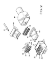
- a modular plug electrical connector 10 which is matable with a modular jack (not shown) for interconnecting a plurality of wires 12 (only one of which is shown) in a communications system.
- the wires in a communications system are typically twisted together in pairs which are associated as signal pairs, and the twisted pairs of wires are bundled within an insulative jacket.
- Each of the individual wires 12 includes a conductive core which is surrounded by a sleeve of insulation.
- the modular plug connector 10 comprises a dielectric housing 20 which holds a plurality of terminals 30 that are arranged side-by-side in respective slots 22 at a forward end 23 of the housing.
- Each of the terminals 30 has a contact face 32 which is adapted for engaging a terminal in the modular jack, and a leg 34 which is adapted for insertion in a hole in a circuit board 40.
- the number of terminals 30 corresponds to the number of wires 12 in the communications cable with which the modular plug is being used.
- the modular plug in the illustrated embodiment is an eight position electrical connector having eight terminals 30 which can be terminated to eight wires 12 of a standard four pair communications cable. However, it should be understood that the invention can be embodied in a modular plug which is configured for terminating any number of wires.
- the terminals 30 are assigned respective numbers 1 thru 8 corresponding to their positions in the housing, and these numbers 1 thru 8 in turn designate respective electrical paths which run through the terminals.
- the housing 20 has a cavity 24 which opens into the housing through a rear face 25 of the housing.
- the cavity 24 is open to the slots 22 in an interior of the housing.
- the housing has a resilient latch arm 26 of known configuration which is operable to releasably secure the modular plug connector to the mating modular jack.
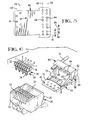
- Each of the circuit holes 41 in the first array is associated with one of the terminals 30 and may be assigned a respective number 1 thru 8 according to the number of its associated terminal 30.
- Each of the circuit holes 41 is preferably a plated circuit hole.
- the circuit holes 41 are arranged in two linear rows 42, 43 that are spaced-apart and extend laterally across the circuit board. Thus, the circuit holes 41 are longitudinally staggered as they extend laterally across the board in order to increase the density of circuit holes having a particular centerline spacing.
- the circuit holes 44 in the second array are arranged in eight pairs corresponding to the eight wires which are to be terminated by the modular plug.
- Each of the circuit hole pairs comprises one circuit hole in lateral row 45 and one circuit hole in lateral row 46. It should be understood that only one circuit hole of each circuit hole pair is required to be electrically connected to a circuit trace on the circuit board.
- the circuit hole pairs are oriented in respective longitudinal rows such as rows 47, 48, 49, and all of the longitudinal rows extend parallel to each other. Further, the longitudinal rows are laterally spaced-apart at non-uniform distances.
- circuit hole pairs in longitudinal rows 47 and 48 which are associated with wires in a same twisted wire pair are spaced-apart by first distance D1
- circuit hole pairs in longitudinal rows 48 and 49 which are associated with wires in different twisted wire pairs are spaced-apart by a second distance D2 which is greater than the first distance D1.
- the distances D1 and D2 are on the order of 1.0mm and 1.5mm (.040 inch and .060 inch), respectively.
- each of the contacts 50 is a planar body having an upper portion including a pair of arms 52 with tips 53 which are configured to pierce the insulation of one of the wires 12, and a lower portion including a pair of legs 54 which are initially straight to permit insertion of the legs through one of the pairs of circuit holes 44. After insertion, the legs 54 are bent as shown in Fig. 9 to clinch the circuit board 40 from below and thereby secure the contact 50 to the circuit board.
- the planar contact bodies are arranged in respective parallel planes and in respective contact pairs in accordance with the footprint of the circuit holes 44.
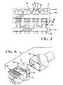
- the modular plug includes a stuffer cap 60.
- the stuffer cap includes a block member 62 having eight wire channels 63 each of which is dimensioned to receive one of the eight wires 12.
- the wire channels 63 are arranged in four siamesed pairs 64 that have an open wall at 65 between the paired wire channels. Each of the siamesed pairs 64 is intended to receive two wires of a same twisted wire pair.
- the wire channels 63 may be tapered in width as they extend axially through the block member 62.
- a cross-sectional dimension of the wire channel 63 in the vicinity of wire entrance 66 may be less than a cross-sectional dimension of the wire channel in the vicinity of wire exit 67, for a reason to be explained.
- the stuffer cap 60 has eight slots 68 which are open from a bottom 69 of the stuffer cap into respective ones of the wire channels 63. Each of the slots 68 is dimensioned to closely receive one of the contacts 50.
- the stuffer cap 60 includes a rigid plate member 70 having a free end which forms pivot members 72.
- the pivot members 72 are joined by a link 73 that spans an opening 74 in the plate member 70.
- a circuit board subassembly comprising the circuit board 40, the contacts 50 and the stuffer cap 60 is installed in the cavity 24 in the housing 20.
- the stuffer cap is disposed in an initial or open position wherein the contacts 50 are partially within the slots 68 but have not entered the wire channels 63.
- the terminals 30, which are initially held in a pre-stage position in the slots 22, are driven downwardly so that the legs 34 of the terminals enter the circuit holes 41 in the circuit board.
- the legs 34 of the terminals serve to mechanically retain the circuit board in the housing and electrically engage with circuit paths on the circuit board.
- the legs 34 may be long enough to extend through the circuit board and into housing material below the circuit board to better retain the board in the housing.
- the stuffer cap 60 With the circuit board in this position, the stuffer cap 60 is trapped between a rear portion 27 of the housing and the contacts 50 which are partially within the slots 68. With the stuffer cap in the open position, pairs of the twisted wires 12 may be inserted in the siamesed pairs 64 of wire channels and pulled forwardly until the cable jacket abuts the rear of the block member 62, thereby minimizing any untwisted length of the wires.
- the stuffer cap is driven to a closed or final position with a suitable tool by pivoting the stuffer cap on the pivot members 72 (Fig. 9) in order to drive the tips 53 of the contact arms 52 through the cores of the wires 12, thereby electrically connecting the wires through the circuit board 40 to the terminals 30. Further, driving the contact arms 52 into the wires causes the insulation of each wire to swell in size, and the swollen insulation in combination with the tapered cross-section of the wire channel 63 results in a wedging action that serves to lock the wires 12 in the wire channels and to provide strain relief for the wires.
- a ledge 28 of the housing is sheared at connecting strip 29 and is driven downwardly behind the link 73 of the stuffer cap in order to provide supplemental retention of the stuffer cap to the modular plug.
- the invention provides a modular plug electrical connector having a circuit board which may include circuit traces that are routed to provide desired electrical couplings between selected circuits, thereby reducing electrical crosstalk in the connector.
- the circuit board is mechanically retained in the modular plug by terminals of the modular plug which are matable with terminals of a modular jack.
- the circuit board has contacts for connecting with wires of a communications system, and a stuffer cap for driving the wires into engagement with the contacts.
- Each of the contacts has a central axis which is inclined from perpendicular to the circuit board.
- the stuffer cap has wire-receiving channels which are arranged in siamesed pairs which receive twisted wire pairs, thereby minimizing any untwisted length of the wires.
Applications Claiming Priority (2)
| Application Number | Priority Date | Filing Date | Title |
|---|---|---|---|
| US107814 | 1998-06-30 | ||
| US09/107,814 US6116943A (en) | 1998-06-30 | 1998-06-30 | Modular plug having a circuit board |
Publications (2)
| Publication Number | Publication Date |
|---|---|
| EP0971444A1 true EP0971444A1 (fr) | 2000-01-12 |
| EP0971444B1 EP0971444B1 (fr) | 2008-08-13 |
Family
ID=22318630
Family Applications (1)
| Application Number | Title | Priority Date | Filing Date |
|---|---|---|---|
| EP99305018A Expired - Lifetime EP0971444B1 (fr) | 1998-06-30 | 1999-06-25 | Fiche modulaire comportant une plaque à circuits imprimés |
Country Status (5)
| Country | Link |
|---|---|
| US (1) | US6116943A (fr) |
| EP (1) | EP0971444B1 (fr) |
| CN (1) | CN2418593Y (fr) |
| DE (1) | DE69939297D1 (fr) |
| TW (1) | TW435874U (fr) |
Cited By (6)
| Publication number | Priority date | Publication date | Assignee | Title |
|---|---|---|---|---|
| DE102007008465A1 (de) * | 2007-02-19 | 2008-08-21 | Tyco Electronics Amp Gmbh | Elektrisches Steckermodul insbesondere für eine RJ 45-Steckverbindung |
| GB2510572A (en) * | 2013-02-07 | 2014-08-13 | 3M Innovative Properties Co | Plug with cross-talk compensation |
| WO2015007939A3 (fr) * | 2013-07-15 | 2015-03-19 | Te Connectivity Amp España, S.L.U. | Connecteur de télécommunications mâle pour des applications de données à haut débit |
| WO2020006586A1 (fr) * | 2018-07-03 | 2020-01-09 | Bertelt Peter | Dispositif de connexion |
| WO2020007952A1 (fr) * | 2018-07-03 | 2020-01-09 | Aqueous Group Ag | Dispositif de connexion |
| EP4195426A1 (fr) * | 2009-06-11 | 2023-06-14 | CommScope, Inc. of North Carolina | Fiches de télécommunication dotées de condensateurs qui injectent une diaphonie offensante après un point de contact fiche-prise et connecteurs et procédés liés |
Families Citing this family (40)
| Publication number | Priority date | Publication date | Assignee | Title |
|---|---|---|---|---|
| FR2791816B1 (fr) * | 1999-04-01 | 2001-06-15 | Infra Sa | Connecteur male basse tension |
| US6338643B1 (en) | 2000-09-29 | 2002-01-15 | Hubbell Incorporated | Stuffer cap mechanism for an electrical connector |
| DE10065136C2 (de) * | 2000-12-29 | 2003-01-09 | Phoenix Contact Gmbh & Co | Anschlußvorrichtung und Verfahren zum Anschließen eines mehradrigen Kabels an einen Steckverbinder |
| US6312281B1 (en) * | 2001-01-08 | 2001-11-06 | Andrew Corporation | Tap connector |
| US6579116B2 (en) | 2001-03-12 | 2003-06-17 | Sentinel Holding, Inc. | High speed modular connector |
| US6439920B1 (en) * | 2001-09-18 | 2002-08-27 | Surtec Industries Inc. | Electronic connector plug for high speed transmission |
| US20030116935A1 (en) * | 2001-12-26 | 2003-06-26 | Adam Zadok | Anti-roll vehicle suspension |
| GB2398677A (en) * | 2003-02-18 | 2004-08-25 | Hsu & Overmatt Co Ltd | Electrical connector with IDC pins |
| BE1015495A3 (fr) * | 2003-03-04 | 2005-05-03 | Hsu & Overmaat Co Ltd | Connecteur electrique pour assemblage automatique. |
| US20040209511A1 (en) * | 2003-04-21 | 2004-10-21 | Liao Sheng Hsin | Electrical plug with protection cover |
| US6776660B1 (en) | 2003-04-30 | 2004-08-17 | Japan Aviation Electronics Industry, Limited | Connector |
| CN100384019C (zh) * | 2003-11-25 | 2008-04-23 | 康福特仪器(杭州)有限公司 | 能剥离绝缘层的电连接器 |
| US6932641B1 (en) * | 2004-02-20 | 2005-08-23 | Sheng Hsin Liao | Plug structure |
| US7001204B1 (en) * | 2005-01-12 | 2006-02-21 | Jyh Eng Technology Co., Ltd. | Transmitting jack with prong-type conductive pieces |
| US20060246784A1 (en) * | 2005-04-29 | 2006-11-02 | Aekins Robert A | Electrically isolated shielded connector system |
| US7322860B2 (en) * | 2006-05-01 | 2008-01-29 | Ortronics, Inc. | Plug assembly including integral printed circuit board |
| US20070254714A1 (en) * | 2006-05-01 | 2007-11-01 | Martich Mark E | Wireless access point |
| TWI310999B (en) * | 2006-05-19 | 2009-06-11 | John Peng | Network jack and method for fabricating the same |
| US7530854B2 (en) * | 2006-06-15 | 2009-05-12 | Ortronics, Inc. | Low noise multiport connector |
| US7288001B1 (en) | 2006-09-20 | 2007-10-30 | Ortronics, Inc. | Electrically isolated shielded multiport connector assembly |
| US20080115356A1 (en) * | 2006-11-17 | 2008-05-22 | Peterson Karl J | Cable preform tool |
| CN101595536B (zh) * | 2006-12-01 | 2013-03-06 | 西蒙公司 | 端接可变性减少的模块化连接器 |
| US7540788B2 (en) * | 2007-01-05 | 2009-06-02 | Apple Inc. | Backward compatible connector system |
| US8095713B2 (en) * | 2007-09-04 | 2012-01-10 | Apple Inc. | Smart cables |
| DE102010014294A1 (de) * | 2010-04-08 | 2011-10-13 | Phoenix Contact Gmbh & Co. Kg | Kontaktfeld für Steckverbinder |
| US7967614B1 (en) | 2010-04-28 | 2011-06-28 | Tyco Electronics Corporation | Plug connector and connector assembly having a pluggable board substrate |
| US7883354B1 (en) * | 2010-08-26 | 2011-02-08 | Hong Fu Jin Precision Industry (Shenzhen) Co., Ltd. | Modular plug |
| US8690598B2 (en) * | 2010-10-21 | 2014-04-08 | Panduit Corp. | Communication plug with improved crosstalk |
| US8591248B2 (en) | 2011-01-20 | 2013-11-26 | Tyco Electronics Corporation | Electrical connector with terminal array |
| US8257117B2 (en) | 2011-01-20 | 2012-09-04 | Tyco Electronics Corporation | Electrical connector having a first group of terminals taller than that of a second group or located in a non-parallel plane |
| US8647146B2 (en) | 2011-01-20 | 2014-02-11 | Tyco Electronics Corporation | Electrical connector having crosstalk compensation insert |
| TWI493808B (zh) * | 2012-11-16 | 2015-07-21 | Frank Ma | Transmission connector |
| US8764476B1 (en) | 2012-12-06 | 2014-07-01 | Frank Ma | Transmission connector |
| US9246265B2 (en) | 2013-03-12 | 2016-01-26 | Commscope Technologies Llc | Notched contact for a modular plug |
| US8992247B2 (en) * | 2013-03-15 | 2015-03-31 | Ortronics, Inc. | Multi-surface contact plug assemblies, systems and methods |
| US9543729B2 (en) | 2013-08-19 | 2017-01-10 | Sullstar Technologies, Inc | Electrical connector with removable external load bar, and method of its use |
| US9640924B2 (en) | 2014-05-22 | 2017-05-02 | Panduit Corp. | Communication plug |
| TWM536801U (zh) | 2016-10-21 | 2017-02-11 | Jyh Eng Technology Co Ltd | 網路插頭結構 |
| TWI757933B (zh) * | 2020-10-27 | 2022-03-11 | 好慶科技企業股份有限公司 | 電子插頭 |
| US11705681B2 (en) * | 2021-08-19 | 2023-07-18 | Panduit Corp. | Field terminable ethernet connector with integral termination cap |
Citations (4)
| Publication number | Priority date | Publication date | Assignee | Title |
|---|---|---|---|---|
| WO1996005635A1 (fr) * | 1994-08-08 | 1996-02-22 | Framatome Connectors International | Prise reseau a faible diaphonie |
| US5628647A (en) * | 1995-02-22 | 1997-05-13 | Stewart Connector Systems, Inc. | High frequency modular plug and cable assembly |
| EP0782221A2 (fr) * | 1995-12-25 | 1997-07-02 | Matsushita Electric Works, Ltd. | Connecteur |
| EP0793305A2 (fr) * | 1996-02-22 | 1997-09-03 | The Whitaker Corporation | Câble à paires torsadées et assemblage de connectuer |
Family Cites Families (3)
| Publication number | Priority date | Publication date | Assignee | Title |
|---|---|---|---|---|
| US5503572A (en) * | 1994-05-17 | 1996-04-02 | Mod-Tap Corporation | Communications connectors |
| US5766027A (en) * | 1995-12-21 | 1998-06-16 | The Whitaker Corporation | Cable assembly with equalizer board |
| DE29804543U1 (de) * | 1998-03-13 | 1998-06-18 | Hsing Chau Ind Co | Modul-Stecker |
-
1998
- 1998-06-30 US US09/107,814 patent/US6116943A/en not_active Expired - Lifetime
-
1999
- 1999-06-25 EP EP99305018A patent/EP0971444B1/fr not_active Expired - Lifetime
- 1999-06-25 DE DE69939297T patent/DE69939297D1/de not_active Expired - Lifetime
- 1999-06-28 TW TW088210622U patent/TW435874U/zh not_active IP Right Cessation
- 1999-06-30 CN CN99215601U patent/CN2418593Y/zh not_active Expired - Lifetime
Patent Citations (4)
| Publication number | Priority date | Publication date | Assignee | Title |
|---|---|---|---|---|
| WO1996005635A1 (fr) * | 1994-08-08 | 1996-02-22 | Framatome Connectors International | Prise reseau a faible diaphonie |
| US5628647A (en) * | 1995-02-22 | 1997-05-13 | Stewart Connector Systems, Inc. | High frequency modular plug and cable assembly |
| EP0782221A2 (fr) * | 1995-12-25 | 1997-07-02 | Matsushita Electric Works, Ltd. | Connecteur |
| EP0793305A2 (fr) * | 1996-02-22 | 1997-09-03 | The Whitaker Corporation | Câble à paires torsadées et assemblage de connectuer |
Cited By (9)
| Publication number | Priority date | Publication date | Assignee | Title |
|---|---|---|---|---|
| DE102007008465A1 (de) * | 2007-02-19 | 2008-08-21 | Tyco Electronics Amp Gmbh | Elektrisches Steckermodul insbesondere für eine RJ 45-Steckverbindung |
| DE102007008465B4 (de) * | 2007-02-19 | 2008-10-16 | Tyco Electronics Amp Gmbh | Elektrisches Steckermodul insbesondere für eine RJ 45-Steckverbindung |
| US7559790B2 (en) | 2007-02-19 | 2009-07-14 | Tyco Electronics Amp Gmbh | Electrical plug module |
| EP4195426A1 (fr) * | 2009-06-11 | 2023-06-14 | CommScope, Inc. of North Carolina | Fiches de télécommunication dotées de condensateurs qui injectent une diaphonie offensante après un point de contact fiche-prise et connecteurs et procédés liés |
| GB2510572A (en) * | 2013-02-07 | 2014-08-13 | 3M Innovative Properties Co | Plug with cross-talk compensation |
| WO2015007939A3 (fr) * | 2013-07-15 | 2015-03-19 | Te Connectivity Amp España, S.L.U. | Connecteur de télécommunications mâle pour des applications de données à haut débit |
| US10056703B2 (en) | 2013-07-15 | 2018-08-21 | CommScope Connectivity Spain, S.L. | Telecommunications plug for high data rate applications |
| WO2020006586A1 (fr) * | 2018-07-03 | 2020-01-09 | Bertelt Peter | Dispositif de connexion |
| WO2020007952A1 (fr) * | 2018-07-03 | 2020-01-09 | Aqueous Group Ag | Dispositif de connexion |
Also Published As
| Publication number | Publication date |
|---|---|
| TW435874U (en) | 2001-05-16 |
| EP0971444B1 (fr) | 2008-08-13 |
| CN2418593Y (zh) | 2001-02-07 |
| DE69939297D1 (de) | 2008-09-25 |
| US6116943A (en) | 2000-09-12 |
Similar Documents
| Publication | Publication Date | Title |
|---|---|---|
| EP0971444B1 (fr) | Fiche modulaire comportant une plaque à circuits imprimés | |
| EP1188204B1 (fr) | Fiche electrique modulaire, ensembles fiche et cable comprenant cette fiche, et barre de charge et broche de borne pour cette fiche | |
| EP1295363B1 (fr) | Connecteur pour transmission d'un signal a haute vitesse | |
| US6524128B2 (en) | Modular plug wire aligner | |
| US6923673B2 (en) | Low crosstalk modular communication connector | |
| US6113400A (en) | Modular plug having compensating insert | |
| US5380223A (en) | High density electrical connector | |
| JP4322364B2 (ja) | モジュラー式通信コネクタ | |
| US7727025B2 (en) | Modular electrical connector with enhanced plug interface | |
| US5971812A (en) | Modular plug having a circuit board | |
| US6582255B2 (en) | High-density plug connector for twisted pair cable | |
| US6332802B2 (en) | Modular plug and harnessed plug | |
| EP0847111B1 (fr) | Fiche modulaire avec fils automatiquement positionnés en quinconce | |
| US5593314A (en) | Staggered terminal array for mod plug | |
| US5997348A (en) | Electrical assembly with grounding strip connecting cable screens | |
| US6234843B1 (en) | Low profile filter connector with ferrite | |
| US4674822A (en) | Multi-conductor shielded cable | |
| US6331120B1 (en) | Electrical connector with reduced crosstalk for high frequency signals | |
| US4874330A (en) | Capacity modular plug | |
| US20040115983A1 (en) | Electrical plug with reduced cross talk | |
| EP1074068B1 (fr) | Prise electrique modulaire et ensemble prise-cable le comprenant | |
| WO1999036994A1 (fr) | Connecteur de montage en saillie pourvu d'une structure terminale amelioree | |
| GB2248528A (en) | Wire-to-wire shielded electrical connecting means | |
| EP1263092B1 (fr) | Connecteur pour câble de réseau | |
| US6074254A (en) | Communication system and communication cable connector assembly |
Legal Events
| Date | Code | Title | Description |
|---|---|---|---|
| PUAI | Public reference made under article 153(3) epc to a published international application that has entered the european phase |
Free format text: ORIGINAL CODE: 0009012 |
|
| AK | Designated contracting states |
Kind code of ref document: A1 Designated state(s): DE FR GB |
|
| AX | Request for extension of the european patent |
Free format text: AL;LT;LV;MK;RO;SI |
|
| 17P | Request for examination filed |
Effective date: 20000623 |
|
| AKX | Designation fees paid |
Free format text: DE FR GB |
|
| GRAP | Despatch of communication of intention to grant a patent |
Free format text: ORIGINAL CODE: EPIDOSNIGR1 |
|
| GRAS | Grant fee paid |
Free format text: ORIGINAL CODE: EPIDOSNIGR3 |
|
| GRAA | (expected) grant |
Free format text: ORIGINAL CODE: 0009210 |
|
| AK | Designated contracting states |
Kind code of ref document: B1 Designated state(s): DE FR GB |
|
| REG | Reference to a national code |
Ref country code: GB Ref legal event code: FG4D |
|
| REF | Corresponds to: |
Ref document number: 69939297 Country of ref document: DE Date of ref document: 20080925 Kind code of ref document: P |
|
| PLBE | No opposition filed within time limit |
Free format text: ORIGINAL CODE: 0009261 |
|
| STAA | Information on the status of an ep patent application or granted ep patent |
Free format text: STATUS: NO OPPOSITION FILED WITHIN TIME LIMIT |
|
| 26N | No opposition filed |
Effective date: 20090514 |
|
| REG | Reference to a national code |
Ref country code: FR Ref legal event code: PLFP Year of fee payment: 18 |
|
| PGFP | Annual fee paid to national office [announced via postgrant information from national office to epo] |
Ref country code: GB Payment date: 20160627 Year of fee payment: 18 |
|
| PGFP | Annual fee paid to national office [announced via postgrant information from national office to epo] |
Ref country code: FR Payment date: 20160628 Year of fee payment: 18 |
|
| PGFP | Annual fee paid to national office [announced via postgrant information from national office to epo] |
Ref country code: DE Payment date: 20160628 Year of fee payment: 18 |
|
| REG | Reference to a national code |
Ref country code: DE Ref legal event code: R119 Ref document number: 69939297 Country of ref document: DE |
|
| GBPC | Gb: european patent ceased through non-payment of renewal fee |
Effective date: 20170625 |
|
| REG | Reference to a national code |
Ref country code: FR Ref legal event code: ST Effective date: 20180228 |
|
| PG25 | Lapsed in a contracting state [announced via postgrant information from national office to epo] |
Ref country code: DE Free format text: LAPSE BECAUSE OF NON-PAYMENT OF DUE FEES Effective date: 20180103 Ref country code: GB Free format text: LAPSE BECAUSE OF NON-PAYMENT OF DUE FEES Effective date: 20170625 |
|
| PG25 | Lapsed in a contracting state [announced via postgrant information from national office to epo] |
Ref country code: FR Free format text: LAPSE BECAUSE OF NON-PAYMENT OF DUE FEES Effective date: 20170630 |