EP0971207A1 - Surveying instrument - Google Patents
Surveying instrument Download PDFInfo
- Publication number
- EP0971207A1 EP0971207A1 EP99113565A EP99113565A EP0971207A1 EP 0971207 A1 EP0971207 A1 EP 0971207A1 EP 99113565 A EP99113565 A EP 99113565A EP 99113565 A EP99113565 A EP 99113565A EP 0971207 A1 EP0971207 A1 EP 0971207A1
- Authority
- EP
- European Patent Office
- Prior art keywords
- surveying instrument
- target
- image
- instrument
- survey station
- Prior art date
- Legal status (The legal status is an assumption and is not a legal conclusion. Google has not performed a legal analysis and makes no representation as to the accuracy of the status listed.)
- Granted
Links
- 238000009428 plumbing Methods 0.000 claims abstract description 35
- 230000003287 optical effect Effects 0.000 claims abstract description 13
- 238000005259 measurement Methods 0.000 description 13
- 239000003550 marker Substances 0.000 description 7
- 238000012937 correction Methods 0.000 description 4
- 241001290864 Schoenoplectus Species 0.000 description 2
- 238000000034 method Methods 0.000 description 2
- 230000005540 biological transmission Effects 0.000 description 1
- 238000006243 chemical reaction Methods 0.000 description 1
- 238000010276 construction Methods 0.000 description 1
- 210000004209 hair Anatomy 0.000 description 1
Images




Classifications
-
- G—PHYSICS
- G01—MEASURING; TESTING
- G01C—MEASURING DISTANCES, LEVELS OR BEARINGS; SURVEYING; NAVIGATION; GYROSCOPIC INSTRUMENTS; PHOTOGRAMMETRY OR VIDEOGRAMMETRY
- G01C15/00—Surveying instruments or accessories not provided for in groups G01C1/00 - G01C13/00
- G01C15/02—Means for marking measuring points
- G01C15/06—Surveyors' staffs; Movable markers
- G01C15/08—Plumbing or registering staffs or markers over ground marks
-
- G—PHYSICS
- G01—MEASURING; TESTING
- G01C—MEASURING DISTANCES, LEVELS OR BEARINGS; SURVEYING; NAVIGATION; GYROSCOPIC INSTRUMENTS; PHOTOGRAMMETRY OR VIDEOGRAMMETRY
- G01C1/00—Measuring angles
- G01C1/02—Theodolites
-
- G—PHYSICS
- G01—MEASURING; TESTING
- G01C—MEASURING DISTANCES, LEVELS OR BEARINGS; SURVEYING; NAVIGATION; GYROSCOPIC INSTRUMENTS; PHOTOGRAMMETRY OR VIDEOGRAMMETRY
- G01C5/00—Measuring height; Measuring distances transverse to line of sight; Levelling between separated points; Surveyors' levels
Definitions
- the present invention relates to a plumbing device for plumbing a surveying instrument and, more particularly, to a plumbing device for plumbing a surveying instrument, capable of calculating dislocations x and y of the surveying instrument from a datum point, and the instrument height H of the surveying instrument.
- a survey instrument is set on a datum point or a given point and measurement is made from the datum point or the given point.
- a theodolite has a sighting telescope mounted so that it is free to rotate around horizontal and vertical axes, and the sight directions of the sighting telescope are measured for survey.
- a leveling instrument is used for measuring the difference of height of a sight position.
- Fig. 9 shows a surveying instrument 9100 mounted on a tripod 9000, and a surveying marker 9200.
- the surveying instrument 9100 is set so that its vertical rotation axis coincides with a vertical line passing a datum point.
- a reference point for measuring instrument height H is formed on a support coinciding with the center of horizontal rotation of a sighting telescope.
- the surveying instrument 9100 is provided with a leveling mechanism 9110 for aligning the tilted vertical rotation axis thereof with the vertical line, and a plumbing telescope 9120 for correcting the horizontal position thereof.
- a datum point lying under the surveying instrument 9100 on the vertical rotation axis can be viewed through a reflecting prism 9130 and the plumbing telescope 9120.
- a surveyor installs the surveying instrument 9100 in alignment with the datum point, measures the instrument height H of the surveying instrument 9100, and measures the distance between the reference point on the support of the surveying instrument 9100 and the surveying marker 9200 with a measuring tape or the like.
- the distance between the point on a lower part of the surveying instrument 9100 and the surveying marker 9200, and the thickness of a mount and the height of the surveying instrument 9100 are added to the distance. Since the height of the surveying instrument 9100 is changed by leveling, the height of the surveying instrument 9100 needs to be measured when installing the surveying instrument 9100, which takes time and accurate measurement cannot be expected.
- the distance between the reference point and the surveying marker 9200 is measured approximately and directly.
- the reference point for measuring the instrument height H does not lie on the vertical line passing the datum point, and hence the accurate measurement of the instrument height H is impossible.
- the surveying instrument 9100 must be set with its vertical rotation axis aligned with the vertical line passing the datum point to achieve accurate surveying and the accurate measurement of the instrument height H.
- the position of the surveying instrument 9100 mounted on the tripod 9000 is adjusted by the leveling mechanism 9110 so that the vertical rotation axis of the surveying instrument 9100 extend vertically. Subsequently, a screw, not shown, fastening the surveying instrument 9100 to the tripod 9000 is unfastened slightly while viewing the plumbing telescope 9120, and the surveying instrument 9100 is moved horizontally to bring the vertical rotation axis of the surveying instrument 9100 into alignment with the vertical line passing the datum point.
- the measuring accuracy of the surveying instrument 9100 has remarkably improved, and the surveying instrument 9100 is capable of highly accurate survey. If a surveying instrument capable of measuring horizontal angles and elevation angles in an accuracy of about 5" is dislocated from a plumb position by 5 mm, an error of about 10" per 100 m is introduced in the measurement of the surveying instrument. Therefore the plumbing work requires highly accurate work of a skilled surveyor. Accordingly, there has been an ardent desire for a means capable of enabling persons other than skilled persons to achieve the highly accurately measurement of the instrument height H.
- Fig. 1 Shown in Fig. 1 are a surveying instrument 1000 and a station marker 2000.
- the surveying instrument 1000 is provided with a plumbing telescope 1100.
- An instrument height measuring target 2100 for measuring instrument height is formed on the station marker 2000 with its center coincided with the center axis of the station marker 2000.
- Fig. 1 shows the surveying instrument 1000 after the completion of a leveling operation and before a plumbing operation using the plumbing telescope 1100.
- a hole 1200 for the passage of a collimation light beam is formed in a central part of the bottom of the surveying instrument 1000.
- a reflecting prism 1300 for perpendicularly deflecting the collimation light beam is disposed on the vertical rotation axis of the surveying instrument 1000.
- a leveling base 3100 is provided with a threaded hole 3110 for use in fastening the leveling base 3100 to a tripod 3000. The threaded hole 3110 can be seen through the hole 1200 of the surveying instrument 1000.
- the collimation light beam traveled through the hole 1200 is reflected by the reflecting prism 1300 toward the plumbing telescope 1100.
- the plumbing telescope 1100 separates the collimating light beam from a measuring light beam.
- the optical construction of the plumbing telescope 1100 will be described with reference to Fig. 2.
- the plumbing telescope 1100 comprises an eyepiece 1110, a reticle 1120, a first beam splitter 1130, an objective lens 1140, a second beam splitter 1150, a first CCD 1160 and a second CCD 1170.
- Target image an image of the instrument height measuring target 2100 (hereinafter referred to simply as "target image") on the reticle 1120 provided with cross hairs.
- the objective lens 1140 and the reticle 1120 correspond to the optical means.
- the surveyor views the target image formed on the reticle 1120 through the eyepiece.
- the first beam splitter 1130 is interposed between the objective lens 1140 and the reticle 1120 to transmit part of the collimation light beam toward the reticle 1120 and to reflect the rest, i.e., a measuring light beam, perpendicularly toward the second beam splitter 1150.
- the second beam splitter 1150 splits the measuring light beam into a first measuring light beam and a second measuring light beam. Part of the measuring light beam reflected by the first beam splitter 1130 travels through the second beam splitter 1150 as the first measuring light beam, and the rest of the same is reflected at a deflection angle of 90° to form the second measuring light beam.
- the first measuring light beam falls on the first CCD 1160, i.e., a first photodetecting means.
- the second measuring light beam falls on the second CCD 1170, i.e., a second photodetecting means.
- the first CCD 1160 and the second CCD 1170 are positionally conjugate with the reticle 1120 with respect to the first beam split
- the instrument height measuring target 2100 consists of concentric circles as shown in Fig. 1.
- Fig. 3 shows the target image formed on the reticle 1120.
- the first CCD 1160 and the second CCD 1170 are disposed with their light receiving surfaces extended perpendicularly to each other. Therefore, the first CCD 1160 is able to measure a position of the target image on the X-axis (Fig. 3), and the second CCD 1170 is able to measure a position of the target image on the Y-axis (Fig. 3).
- Fig. 3 shows the relation between the target image formed on the reticle 1120, and the first CCD 1160 and the second CCD 1170.
- a dislocation of the reference point from the datum point along the X-axis is represented by x
- a dislocation of the reference point from the datum point along the Y-axis is represented by y.
- the dislocation x is equal to the distance between a 0 point on the X-axis and the middle point of one of intervals between adjacent intersections of the X-axis and the concentric circles different from the other intervals.
- the dislocation y is equal to the distance between a 0 point on the Y-axis and the middle point of one of intervals between adjacent intersections of the Y-axis and the concentric circles different from the other intervals.
- the dislocations x and y are calculated by a proper processing means.
- the radius of specified one of the circular images forming the target image can be calculated by applying the dislocation x or y, and a value equal to half the different interval to the theorem of three squares.
- the diameters of circular images crossing the first CCD 1160 or the second CCD 1170 can be calculated by measuring the number of intersections of the X-axis or the Y-axis, and the circular images, and the intervals between the intersections of the X-axis or the Y-axis, and the circular images.
- the dislocations x and y can be calculated by applying the radius of a specified circular image and the 1/2 distance to the theorem of three squares.
- the instrument height H i.e. the distance between the reference point and the instrument height measuring target 2100, can simply determined by conversion using the optical magnification of the target image.
- this embodiment employs the two photodetecting means, i.e., the first and the second CCD
- the embodiment may employ a single photodetecting means, and the photodetecting means or the surveying instrument 1000 may be turned through an angle of 90° after measurement from one direction.
- the dislocations x and y and the instrument height H thus measured may be displayed on the screen of a display unit 1400 (Fig. 8) included in the surveying instrument 1000.
- the instrument height measuring target 2100 for instrument height measurement is a pattern of concentric circles.
- the instrument height measuring target 2100 is not limited necessarily to the pattern of concentric circles, but may be a rectangle as shown in Fig. 4. Although the first and the second photodetecting means intersect the center line of the rectangle in Fig. 4, the same can be used when the position between the first and the second photodetecting means is turned.
- the dislocation x can be calculated by comparing length between the intersection points a and b of the first CCD and the target image, and the length between the intersection point c and d of the second CCD and the target image.
- the dislocation y can be calculated on the basis of the positions of the intersections of the first and the second CCD, and the target image.
- an amount of turning is calculated on the basis of the positions of the intersections of the first and the second CCD, and the target image, and the dislocations can be calculated.
- the surveying instrument 1000 may be turned for dislocation correction.
- the instrument height H i.e., the distance between the reference point and the instrument height measuring target 2100, can be calculated on the basis of the ratio of light receiving positions on the first and the second CCD.
- an instrument height measuring target as shown in Fig. 5 may be used.
- Fig. 6 is a view of assistance in explaining a case where a single photodetecting means is used.
- the photodetecting means is disposed so as to cross a W-shaped target image.
- distances between intersection points a and b, intersection points b and c, and intersection points c and d are different. Therefore, dislocation x can be calculated on the basis of the distance between the intersection points a and b and the distance between the intersection points c and d.
- dislocation y can be calculated from a light receiving position.
- a total station i.e., a surveying instrument most prevalently used in recent years, measures horizontal angle and elevation angle electrically, and is provided with a built-in electrooptical distance meter for distance measurement.
- the total station is provided with a high-speed processing means.
- the processing means receives dislocations of the reference point from the datum point, and instrument height H and is capable of automatically displaying true measured values determined by correction.
- the total station is provided with a light transmission encoder as an angle measuring means, and is internally provided with a processing means for processing light reception signals provided by the photodetecting means. Therefore, the total station does not need an additional processing means for processing light reception signals provided by the photodetecting means upon the reception of light representing the target image.
- the surveying instrument 100 is installed in step S1, and the surveying instrument 1000 is leveled in step S2.
- the instrument height measuring target 2100 is placed at the datum point in step S3.
- the surveyor plumbs the surveying instrument 1000 approximately in step S4.
- step S5 a dislocation x, a dislocation y and a instrument height H are measured by the procedure mentioned above.
- Measured values are stored in a storage means included in the surveying instrument 1000 in step S6.
- the stored measured values are displayed on the screen of the display unit 1400 of the surveying instrument 1000 in step S7.
- step S8 When the surveying instrument 1000 is a total station, operations for distance and angle measurement are carried out in step S8. Corrections for correcting distances and angles measured in step S8 are calculated by using the measured values (dislocation x, dislocation y and instrument height H) stored in the storage means in step S6. The corrections calculated in step S9 are displayed on the screen of the display unit 1400 in step S10.
- the distance measuring operation to be carried out in step S8 may use an electrooptical distance meter.
- the angle measuring operation to be carried out in step S8 may use an elevation angle encoder 1510 (Fig. 8) for elevation angle measurement and a horizontal angle encoder 1520 for horizontal angle measurement. If a laser plumbing device capable of indicating the plumb position with a laser beam, the position may approximately be adjusted. Accordingly, the efficiency of the survey work can be improved.
- an image of the target placed at a survey station is formed to indicate the survey station
- the photodetecting means receives an image of the target and provides an image signal
- the processing means calculates an instrument height corresponding to the distance between the reference point on the surveying instrument and the target and dislocations from the station.
- a plumbing device for plumbing a surveying instrument in a surveying instrument capable of electrically measuring at least horizontal angle and elevation angle, a plumbing device for plumbing a surveying instrument, the optical means forms an image of a target placed at a survey station to indicate the survey station, the photodetecting means receives an image of the target and provides an image signal, the processing means calculates instrument height corresponding to the distance between the reference point on the surveying instrument and the target and dislocations from the survey station, and the processing means corrects horizontal angle and elevation angle or corrects distance. Accordingly, the efficiency of surveying work can be improved and accurate survey can be achieved.
Landscapes
- Physics & Mathematics (AREA)
- Engineering & Computer Science (AREA)
- General Physics & Mathematics (AREA)
- Radar, Positioning & Navigation (AREA)
- Remote Sensing (AREA)
- Measurement Of Optical Distance (AREA)
- Length Measuring Devices By Optical Means (AREA)
Abstract
Description
- The present invention relates to a plumbing device for plumbing a surveying instrument and, more particularly, to a plumbing device for plumbing a surveying instrument, capable of calculating dislocations x and y of the surveying instrument from a datum point, and the instrument height H of the surveying instrument.
- Generally, survey work is carried out with reference to a datum point. A survey instrument is set on a datum point or a given point and measurement is made from the datum point or the given point. For example, a theodolite has a sighting telescope mounted so that it is free to rotate around horizontal and vertical axes, and the sight directions of the sighting telescope are measured for survey. A leveling instrument is used for measuring the difference of height of a sight position.
- These survey instruments are used on a tripod. Therefore, the height of the sighting telescope from the ground, i.e., instrument height necessary for calculating difference of elevation, must be measured.
- Fig. 9 shows a
surveying instrument 9100 mounted on atripod 9000, and asurveying marker 9200. Thesurveying instrument 9100 is set so that its vertical rotation axis coincides with a vertical line passing a datum point. A reference point for measuring instrument height H is formed on a support coinciding with the center of horizontal rotation of a sighting telescope. - As shown in Fig. 10, the
surveying instrument 9100 is provided with aleveling mechanism 9110 for aligning the tilted vertical rotation axis thereof with the vertical line, and aplumbing telescope 9120 for correcting the horizontal position thereof. A datum point lying under thesurveying instrument 9100 on the vertical rotation axis can be viewed through a reflectingprism 9130 and theplumbing telescope 9120. - A surveyor installs the
surveying instrument 9100 in alignment with the datum point, measures the instrument height H of thesurveying instrument 9100, and measures the distance between the reference point on the support of thesurveying instrument 9100 and thesurveying marker 9200 with a measuring tape or the like. - When measuring the instrument height H of the
conventional surveying instrument 9100, the distance between the point on a lower part of thesurveying instrument 9100 and thesurveying marker 9200, and the thickness of a mount and the height of thesurveying instrument 9100 are added to the distance. Since the height of thesurveying instrument 9100 is changed by leveling, the height of thesurveying instrument 9100 needs to be measured when installing thesurveying instrument 9100, which takes time and accurate measurement cannot be expected. - Usually, the distance between the reference point and the
surveying marker 9200 is measured approximately and directly. In some cases, the reference point for measuring the instrument height H does not lie on the vertical line passing the datum point, and hence the accurate measurement of the instrument height H is impossible. - The
surveying instrument 9100 must be set with its vertical rotation axis aligned with the vertical line passing the datum point to achieve accurate surveying and the accurate measurement of the instrument height H. - First the position of the
surveying instrument 9100 mounted on thetripod 9000 is adjusted by theleveling mechanism 9110 so that the vertical rotation axis of thesurveying instrument 9100 extend vertically. Subsequently, a screw, not shown, fastening thesurveying instrument 9100 to thetripod 9000 is unfastened slightly while viewing theplumbing telescope 9120, and thesurveying instrument 9100 is moved horizontally to bring the vertical rotation axis of thesurveying instrument 9100 into alignment with the vertical line passing the datum point. - This adjustment work requires very high skill. An error is introduced into the level of the
surveying instrument 9100 or thetripod 9000 is moved unless the adjustment work is carried out very carefully. - Recently, the measuring accuracy of the
surveying instrument 9100 has remarkably improved, and thesurveying instrument 9100 is capable of highly accurate survey. If a surveying instrument capable of measuring horizontal angles and elevation angles in an accuracy of about 5" is dislocated from a plumb position by 5 mm, an error of about 10" per 100 m is introduced in the measurement of the surveying instrument. Therefore the plumbing work requires highly accurate work of a skilled surveyor. Accordingly, there has been an ardent desire for a means capable of enabling persons other than skilled persons to achieve the highly accurately measurement of the instrument height H. - Accordingly, it is an object of the present invention to provide a plumbing device for plumbing a surveying instrument capable of calculating dislocations x and y of the surveying instrument from a datum point, and the instrument height H of the surveying instrument.
- According to one aspect of the present invention, a plumbing device for plumbing a surveying instrument, capable of calculating the instrument height H of the surveying instrument comprises optical means for forming an image of a target placed at a survey station to indicate the station; photodetecting means for receiving an image of the target and providing an image signal, and processing means for calculating instrument height corresponding to the distance between a reference point on the surveying instrument and the target and dislocation from the station.
-
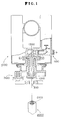
- Fig. 1 is a sectional view of a surveying instrument in a preferred embodiment according to the present invention;
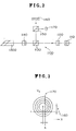
- Fig. 2 is a diagrammatic view of an optical system included in a plumbing telescope;
- Fig. 3 is a diagrammatic view of assistance in explaining a principle on which the surveying instrument shown in Fig. 1 is based;
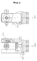
- Fig. 4 is a diagrammatic view of assistance in explaining a principle on which the surveying instrument shown in Fig. 1 is based;
- Fig. 5 is a diagrammatic view of assistance in explaining a principle on which the surveying instrument shown in Fig. 1 is based;
- Fig. 6 is a diagrammatic view of assistance in explaining a principle on which the surveying instrument shown in Fig. 1 is based;
- Fig. 7 is a flow chart of a procedure to be carried out by the surveying instrument shown in Fig. 1;
- Fig. 8 is a partly cutaway front view of a display unit included in a total station;
- Fig. 9 is a perspective view of a conventional surveying instrument; and
- Fig. 10 is a partly sectional front view of the surveying instrument shown in Fig. 9.
-
- Shown in Fig. 1 are a
surveying instrument 1000 and astation marker 2000. Thesurveying instrument 1000 is provided with aplumbing telescope 1100. An instrumentheight measuring target 2100 for measuring instrument height is formed on thestation marker 2000 with its center coincided with the center axis of thestation marker 2000. Fig. 1 shows thesurveying instrument 1000 after the completion of a leveling operation and before a plumbing operation using theplumbing telescope 1100. - A
hole 1200 for the passage of a collimation light beam is formed in a central part of the bottom of thesurveying instrument 1000. A reflectingprism 1300 for perpendicularly deflecting the collimation light beam is disposed on the vertical rotation axis of thesurveying instrument 1000. Aleveling base 3100 is provided with a threadedhole 3110 for use in fastening theleveling base 3100 to a tripod 3000. The threadedhole 3110 can be seen through thehole 1200 of thesurveying instrument 1000. - The collimation light beam traveled through the
hole 1200 is reflected by the reflectingprism 1300 toward theplumbing telescope 1100. Theplumbing telescope 1100 separates the collimating light beam from a measuring light beam. - The optical construction of the
plumbing telescope 1100 will be described with reference to Fig. 2. Theplumbing telescope 1100 comprises aneyepiece 1110, areticle 1120, afirst beam splitter 1130, anobjective lens 1140, asecond beam splitter 1150, afirst CCD 1160 and asecond CCD 1170. - Light reflected by the reflecting
prism 1300 is focused by theobjective lens 1140 to form an image of the instrument height measuring target 2100 (hereinafter referred to simply as "target image") on thereticle 1120 provided with cross hairs. Theobjective lens 1140 and thereticle 1120 correspond to the optical means. The surveyor views the target image formed on thereticle 1120 through the eyepiece. - The
first beam splitter 1130 is interposed between theobjective lens 1140 and thereticle 1120 to transmit part of the collimation light beam toward thereticle 1120 and to reflect the rest, i.e., a measuring light beam, perpendicularly toward thesecond beam splitter 1150. Thesecond beam splitter 1150 splits the measuring light beam into a first measuring light beam and a second measuring light beam. Part of the measuring light beam reflected by thefirst beam splitter 1130 travels through thesecond beam splitter 1150 as the first measuring light beam, and the rest of the same is reflected at a deflection angle of 90° to form the second measuring light beam. The first measuring light beam falls on thefirst CCD 1160, i.e., a first photodetecting means. The second measuring light beam falls on thesecond CCD 1170, i.e., a second photodetecting means. Thefirst CCD 1160 and thesecond CCD 1170 are positionally conjugate with thereticle 1120 with respect to thefirst beam splitter 1130. - A principle of measurement of instrument height H will be described hereinafter. The instrument
height measuring target 2100 consists of concentric circles as shown in Fig. 1. Fig. 3 shows the target image formed on thereticle 1120. - The
first CCD 1160 and thesecond CCD 1170 are disposed with their light receiving surfaces extended perpendicularly to each other. Therefore, thefirst CCD 1160 is able to measure a position of the target image on the X-axis (Fig. 3), and thesecond CCD 1170 is able to measure a position of the target image on the Y-axis (Fig. 3). Fig. 3 shows the relation between the target image formed on thereticle 1120, and thefirst CCD 1160 and thesecond CCD 1170. - A dislocation of the reference point from the datum point along the X-axis is represented by x, and a dislocation of the reference point from the datum point along the Y-axis is represented by y. The dislocation x is equal to the distance between a 0 point on the X-axis and the middle point of one of intervals between adjacent intersections of the X-axis and the concentric circles different from the other intervals. Similarly, the dislocation y is equal to the distance between a 0 point on the Y-axis and the middle point of one of intervals between adjacent intersections of the Y-axis and the concentric circles different from the other intervals. The dislocations x and y are calculated by a proper processing means. The radius of specified one of the circular images forming the target image can be calculated by applying the dislocation x or y, and a value equal to half the different interval to the theorem of three squares.
- Since the circumferences of the circular images are known, the diameters of circular images crossing the
first CCD 1160 or thesecond CCD 1170 can be calculated by measuring the number of intersections of the X-axis or the Y-axis, and the circular images, and the intervals between the intersections of the X-axis or the Y-axis, and the circular images. - Since the half the distance (1/2 distance) between the two zero-cross points can readily be measured, the dislocations x and y can be calculated by applying the radius of a specified circular image and the 1/2 distance to the theorem of three squares.
- Since the diameters of the circles forming the instrument height measuring target are known, the instrument height H, i.e. the distance between the reference point and the instrument
height measuring target 2100, can simply determined by conversion using the optical magnification of the target image. - Although this embodiment employs the two photodetecting means, i.e., the first and the second CCD, the embodiment may employ a single photodetecting means, and the photodetecting means or the
surveying instrument 1000 may be turned through an angle of 90° after measurement from one direction. - The dislocations x and y and the instrument height H thus measured may be displayed on the screen of a display unit 1400 (Fig. 8) included in the
surveying instrument 1000. - The instrument
height measuring target 2100 for instrument height measurement is a pattern of concentric circles. The instrumentheight measuring target 2100 is not limited necessarily to the pattern of concentric circles, but may be a rectangle as shown in Fig. 4. Although the first and the second photodetecting means intersect the center line of the rectangle in Fig. 4, the same can be used when the position between the first and the second photodetecting means is turned. - The dislocation x can be calculated by comparing length between the intersection points a and b of the first CCD and the target image, and the length between the intersection point c and d of the second CCD and the target image. The dislocation y can be calculated on the basis of the positions of the intersections of the first and the second CCD, and the target image.
- When turned and tilted, an amount of turning is calculated on the basis of the positions of the intersections of the first and the second CCD, and the target image, and the dislocations can be calculated. The
surveying instrument 1000 may be turned for dislocation correction. - Since the dimensions of the rectangular instrument height measuring target are known, the instrument height H, i.e., the distance between the reference point and the instrument
height measuring target 2100, can be calculated on the basis of the ratio of light receiving positions on the first and the second CCD. Similarly, an instrument height measuring target as shown in Fig. 5 may be used. - Fig. 6 is a view of assistance in explaining a case where a single photodetecting means is used. The photodetecting means is disposed so as to cross a W-shaped target image. When turned, distances between intersection points a and b, intersection points b and c, and intersection points c and d are different. Therefore, dislocation x can be calculated on the basis of the distance between the intersection points a and b and the distance between the intersection points c and d. Similarly, dislocation y can be calculated from a light receiving position.
- A total station, i.e., a surveying instrument most prevalently used in recent years, measures horizontal angle and elevation angle electrically, and is provided with a built-in electrooptical distance meter for distance measurement. The total station is provided with a high-speed processing means. The processing means receives dislocations of the reference point from the datum point, and instrument height H and is capable of automatically displaying true measured values determined by correction. The total station is provided with a light transmission encoder as an angle measuring means, and is internally provided with a processing means for processing light reception signals provided by the photodetecting means. Therefore, the total station does not need an additional processing means for processing light reception signals provided by the photodetecting means upon the reception of light representing the target image.
- The operation of the
surveying instrument 1000 will be described hereinafter with reference to Fig. 7. - The surveying instrument 100 is installed in step S1, and the
surveying instrument 1000 is leveled in step S2. The instrumentheight measuring target 2100 is placed at the datum point in step S3. The surveyor plumbs thesurveying instrument 1000 approximately in step S4. In step S5, a dislocation x, a dislocation y and a instrument height H are measured by the procedure mentioned above. Measured values are stored in a storage means included in thesurveying instrument 1000 in step S6. The stored measured values are displayed on the screen of thedisplay unit 1400 of thesurveying instrument 1000 in step S7. - When the
surveying instrument 1000 is a total station, operations for distance and angle measurement are carried out in step S8. Corrections for correcting distances and angles measured in step S8 are calculated by using the measured values (dislocation x, dislocation y and instrument height H) stored in the storage means in step S6. The corrections calculated in step S9 are displayed on the screen of thedisplay unit 1400 in step S10. - The distance measuring operation to be carried out in step S8 may use an electrooptical distance meter. The angle measuring operation to be carried out in step S8 may use an elevation angle encoder 1510 (Fig. 8) for elevation angle measurement and a
horizontal angle encoder 1520 for horizontal angle measurement. If a laser plumbing device capable of indicating the plumb position with a laser beam, the position may approximately be adjusted. Accordingly, the efficiency of the survey work can be improved. - As is apparent from the foregoing description, according to the present invention, an image of the target placed at a survey station is formed to indicate the survey station, the photodetecting means receives an image of the target and provides an image signal, and the processing means calculates an instrument height corresponding to the distance between the reference point on the surveying instrument and the target and dislocations from the station. Thus, the instrument height and the dislocations can automatically be measured in high accuracies without requiring any skilled hand.
- According to the present invention, in a surveying instrument capable of electrically measuring at least horizontal angle and elevation angle, a plumbing device for plumbing a surveying instrument, the optical means forms an image of a target placed at a survey station to indicate the survey station, the photodetecting means receives an image of the target and provides an image signal, the processing means calculates instrument height corresponding to the distance between the reference point on the surveying instrument and the target and dislocations from the survey station, and the processing means corrects horizontal angle and elevation angle or corrects distance. Accordingly, the efficiency of surveying work can be improved and accurate survey can be achieved.
Claims (10)
- A plumbing device for plumbing a surveying instrument, comprising:optical means for forming an image of a target placed at a survey station to indicate the survey station;photodetecting means for receiving an image of the target and providing an image signal; andprocessing means for calculating instrument height corresponding to distance between the surveying instrument and the target on the basis of the image signal provided by the photodetecting means.
- A plumbing device for plumbing a surveying instrument, comprising:optical means for forming an image of a target placed at a survey station to indicate the survey station;photodetecting means for receiving an image of the target and providing an image signal; andprocessing means for calculating dislocations of the surveying instrument from the survey station.
- The plumbing device according to claim 1 or 2, wherein the photodetecting means comprises a first photodetecting means, and a second photodetecting means disposed with its light receiving surface extended perpendicularly to that of the first photodetecting means.
- The plumbing device according to any one of claims 1 to 3, wherein the target is a pattern of concentric circles.
- The plumbing device according to claim 4, wherein the photodetecting means provides signals indicating intersections of circular images of the target having the pattern of concentric circles, and an X- or a Y-axis, and the processing means calculates the diameters of the circular images on the basis of the positions of the intersection points and calculates an instrument height corresponding to the diameters.
- The plumbing device according to claim 4, wherein the photodetecting means provides signals indicating intersections of circular images of the target having the pattern of concentric circles, and an X- or a Y-axis, and the processing means calculates a dislocation along the X-axis or a dislocation along the Y-axis on the basis of the positions of the intersection points.
- A surveying instrument capable of electrically measuring at least horizontal angle and elevation angle, said surveying instrument comprising:optical means for forming an image of a target placed at a survey station to indicate the survey station;photodetecting means for receiving an image of the target and providing an image signal; andprocessing means for calculating instrument height corresponding to distance between the surveying instrument and the target, and correcting the horizontal angle and the elevation angle on the basis of the instrument height.
- A surveying instrument capable of electrically measuring at least horizontal angle and elevation angle, said surveying instrument comprising:optical means for forming an image of a target placed at a survey station to indicate the survey station;photodetecting means for receiving an image of the target and providing an image signal; andprocessing means for calculating dislocations from the survey station on the basis of the image signal provided by the photodetecting means, and corrects the horizontal angle and the elevation angle on the basis of the dislocations.
- A surveying instrument capable of electrically measuring at least distance, said surveying instrument comprising:optical means for forming an image of a target placed at a survey station to indicate the survey station;photodetecting means for receiving an image of the target and providing an image signal; andprocessing means for calculating an instrument height equal to distance between the surveying instrument and the target on the basis of the image signal provided by the photodetecting means, and correcting the distance on the basis of the instrument height.
- A surveying instrument capable of electrically measuring at least distance, said surveying instrument comprising:optical means for forming an image of a target placed at a survey station to indicate the survey station;photodetecting means for receiving an image of the target and providing an image signal; andprocessing means for calculating dislocations of the surveying instrument from the survey station on the basis of the image signal provided by the photodetecting means and correcting the distance on the basis of the dislocations.
Applications Claiming Priority (2)
| Application Number | Priority Date | Filing Date | Title |
|---|---|---|---|
| JP20868998 | 1998-07-08 | ||
| JP20868998A JP3965593B2 (en) | 1998-07-08 | 1998-07-08 | Surveying device centripetal position measuring device and surveying instrument |
Publications (2)
| Publication Number | Publication Date |
|---|---|
| EP0971207A1 true EP0971207A1 (en) | 2000-01-12 |
| EP0971207B1 EP0971207B1 (en) | 2007-01-24 |
Family
ID=16560452
Family Applications (1)
| Application Number | Title | Priority Date | Filing Date |
|---|---|---|---|
| EP99113565A Expired - Lifetime EP0971207B1 (en) | 1998-07-08 | 1999-07-07 | Surveying instrument having a plumbing device |
Country Status (4)
| Country | Link |
|---|---|
| US (1) | US6453569B1 (en) |
| EP (1) | EP0971207B1 (en) |
| JP (1) | JP3965593B2 (en) |
| DE (1) | DE69934940T2 (en) |
Cited By (11)
| Publication number | Priority date | Publication date | Assignee | Title |
|---|---|---|---|---|
| WO2008077432A1 (en) * | 2006-12-27 | 2008-07-03 | Trimble Ab | Geodetic instrument and related method |
| WO2009100773A1 (en) * | 2008-02-12 | 2009-08-20 | Trimble Ab | Localization of a surveying instrument in relation to a ground mark |
| CN102128636A (en) * | 2010-12-22 | 2011-07-20 | 王四明 | Method for correcting eccentricity of vertical circle |
| US8625086B2 (en) | 2008-02-12 | 2014-01-07 | Trimble Ab | Determining coordinates of a target in relation to a survey instrument having a camera |
| US8897482B2 (en) | 2008-02-29 | 2014-11-25 | Trimble Ab | Stereo photogrammetry from a single station using a surveying instrument with an eccentric camera |
| US9189858B2 (en) | 2008-02-29 | 2015-11-17 | Trimble Ab | Determining coordinates of a target in relation to a survey instrument having at least two cameras |
| CN108507531A (en) * | 2018-04-18 | 2018-09-07 | 湖南科技大学 | The high laser measurement system of total powerstation instrument and application method |
| DE102005024525B4 (en) | 2004-07-30 | 2019-08-08 | Topcon Corporation | Measurement method and method for correcting a measured value |
| EP3660451A1 (en) * | 2018-11-28 | 2020-06-03 | Hexagon Technology Center GmbH | Intelligent stationing module |
| CN112483825A (en) * | 2020-11-12 | 2021-03-12 | 武汉理工大学 | Theodolite capable of automatically calibrating and leveling |
| CN120315060A (en) * | 2025-06-18 | 2025-07-15 | 中国地震局地质研究所 | Fault zone dislocation measurement method, device and electronic equipment |
Families Citing this family (18)
| Publication number | Priority date | Publication date | Assignee | Title |
|---|---|---|---|---|
| CA2292249C (en) * | 1999-11-19 | 2007-05-22 | Darrell G. B. Cline | Hydrant monument |
| JP4317639B2 (en) * | 2000-03-29 | 2009-08-19 | 株式会社トプコン | Laser surveyor |
| JP4588240B2 (en) * | 2001-04-04 | 2010-11-24 | 株式会社トプコン | Centripetal guidance device |
| JP3840119B2 (en) * | 2002-02-08 | 2006-11-01 | 株式会社ソキア | Laser centripetal device |
| WO2007090309A1 (en) * | 2006-02-08 | 2007-08-16 | Leica Geosystems Ag | Angle measuring device |
| US7748126B2 (en) * | 2007-10-17 | 2010-07-06 | Jianhong Lu | Laser straight liner |
| DE102011002696A1 (en) * | 2011-01-14 | 2012-07-19 | Homag Holzbearbeitungssysteme Gmbh | processing device |
| US8539685B2 (en) | 2011-01-20 | 2013-09-24 | Trimble Navigation Limited | Integrated surveying and leveling |
| CN105300345B (en) * | 2015-11-10 | 2017-09-12 | 中国科学院长春光学精密机械与物理研究所 | Multi-target Tracking Method for Photoelectric Theodolite |
| CN105973191B (en) * | 2016-06-16 | 2018-05-29 | 中国科学院西安光学精密机械研究所 | A Multi-Load Universal Tracking Platform |
| EP3264034B1 (en) | 2016-06-30 | 2020-02-26 | Leica Geosystems AG | Measuring device with height measurement system and method for measuring a height |
| CN106403916B (en) * | 2016-12-02 | 2018-10-02 | 淮阴工学院 | The total powerstation and its working method of alignment are measured based on digital image |
| CN107727119B (en) * | 2017-12-08 | 2023-09-29 | 江西省测绘成果质量监督检验测试中心 | Total station ranging three-axis coincidence degree indoor detection and adjustment device |
| JP6996961B2 (en) * | 2017-12-19 | 2022-01-17 | 株式会社トプコン | Surveying device |
| CN109974673B (en) * | 2019-03-11 | 2024-03-15 | 中国人民解放军63883部队 | Multifunctional fast and precise aiming point finder |
| RU2730370C1 (en) * | 2019-10-21 | 2020-08-21 | Федеральное государственное унитарное предприятие "Научно-производственный центр автоматики и приборостроения имени академика Н.А. Пилюгина" (ФГУП "НПЦАП") | Automated device for attachment to reverse plumb lines |
| JP7438881B2 (en) * | 2020-07-29 | 2024-02-27 | 株式会社トプコン | Leveling platform, surveying equipment and surveying system |
| CN117516378B (en) * | 2023-11-09 | 2025-10-10 | 中电信智能网络科技有限公司 | Installation method determination method, device and electronic equipment |
Citations (3)
| Publication number | Priority date | Publication date | Assignee | Title |
|---|---|---|---|---|
| US5159760A (en) * | 1990-03-08 | 1992-11-03 | Leica Heerbrugg Ag | Device for aligning a geodetic instrument over a defined position mark |
| JPH09257481A (en) * | 1996-03-26 | 1997-10-03 | Nikon Corp | Instrument high measuring instrument with surveying attachment |
| DE19716304C1 (en) * | 1997-04-18 | 1998-05-20 | Zeiss Carl Jena Gmbh | Geodetic device for plumbline, theodolite or tachymeter |
Family Cites Families (11)
| Publication number | Priority date | Publication date | Assignee | Title |
|---|---|---|---|---|
| US4171907A (en) * | 1978-05-25 | 1979-10-23 | Cubic Western Data | Electro-optic distance measuring device |
| JPS6065870A (en) * | 1983-09-19 | 1985-04-15 | 大成建設株式会社 | Pillar installation vertical detection device |
| CH672024A5 (en) * | 1987-03-02 | 1989-10-13 | Wild Leitz Ag Optik Feinmechan | |
| SE500856C2 (en) * | 1989-04-06 | 1994-09-19 | Geotronics Ab | Arrangements for use in surveying and / or launching work |
| US5218770A (en) * | 1990-11-27 | 1993-06-15 | Asahi Seimitsu Kabushiki Kaisha | Surveying machine for construction work |
| JP3226970B2 (en) * | 1992-07-09 | 2001-11-12 | 株式会社トプコン | Laser surveying machine |
| US5392521A (en) * | 1993-06-10 | 1995-02-28 | Allen; Michael P. | Surveyor's prism target |
| JP3681198B2 (en) * | 1995-05-25 | 2005-08-10 | 株式会社トプコン | Laser surveyor |
| JP3670075B2 (en) * | 1996-03-06 | 2005-07-13 | 株式会社トプコン | Appropriate height display device |
| US5949548A (en) * | 1997-01-22 | 1999-09-07 | Asahi Kogaku Kogyo Kabushiki Kaisha | Height sensing measurement device |
| JP3731021B2 (en) * | 1997-01-31 | 2006-01-05 | 株式会社トプコン | Position detection surveying instrument |
-
1998
- 1998-07-08 JP JP20868998A patent/JP3965593B2/en not_active Expired - Fee Related
-
1999
- 1999-07-07 DE DE69934940T patent/DE69934940T2/en not_active Expired - Lifetime
- 1999-07-07 EP EP99113565A patent/EP0971207B1/en not_active Expired - Lifetime
- 1999-07-08 US US09/348,211 patent/US6453569B1/en not_active Expired - Lifetime
Patent Citations (3)
| Publication number | Priority date | Publication date | Assignee | Title |
|---|---|---|---|---|
| US5159760A (en) * | 1990-03-08 | 1992-11-03 | Leica Heerbrugg Ag | Device for aligning a geodetic instrument over a defined position mark |
| JPH09257481A (en) * | 1996-03-26 | 1997-10-03 | Nikon Corp | Instrument high measuring instrument with surveying attachment |
| DE19716304C1 (en) * | 1997-04-18 | 1998-05-20 | Zeiss Carl Jena Gmbh | Geodetic device for plumbline, theodolite or tachymeter |
Non-Patent Citations (1)
| Title |
|---|
| PATENT ABSTRACTS OF JAPAN vol. 1998, no. 02 30 January 1998 (1998-01-30) * |
Cited By (22)
| Publication number | Priority date | Publication date | Assignee | Title |
|---|---|---|---|---|
| DE102005024525B4 (en) | 2004-07-30 | 2019-08-08 | Topcon Corporation | Measurement method and method for correcting a measured value |
| WO2008077432A1 (en) * | 2006-12-27 | 2008-07-03 | Trimble Ab | Geodetic instrument and related method |
| US7908752B2 (en) | 2006-12-27 | 2011-03-22 | Trimble Ab | Geodetic instrument and related method |
| CN101568800B (en) * | 2006-12-27 | 2011-08-17 | 特林布尔公司 | Geodetic instrument and related method |
| WO2009100773A1 (en) * | 2008-02-12 | 2009-08-20 | Trimble Ab | Localization of a surveying instrument in relation to a ground mark |
| WO2009100774A1 (en) * | 2008-02-12 | 2009-08-20 | Trimble Ab | Localizing a surveying instrument in relation to a ground mark |
| CN101932905B (en) * | 2008-02-12 | 2012-12-12 | 特林布尔公司 | Localization of a surveying instrument in relation to a ground mark |
| US8345928B2 (en) | 2008-02-12 | 2013-01-01 | Trimble Ab | Localizing a surveying instrument in relation to a ground mark |
| US8625086B2 (en) | 2008-02-12 | 2014-01-07 | Trimble Ab | Determining coordinates of a target in relation to a survey instrument having a camera |
| US8629905B2 (en) | 2008-02-12 | 2014-01-14 | Trimble Ab | Localization of a surveying instrument in relation to a ground mark |
| US8897482B2 (en) | 2008-02-29 | 2014-11-25 | Trimble Ab | Stereo photogrammetry from a single station using a surveying instrument with an eccentric camera |
| US9189858B2 (en) | 2008-02-29 | 2015-11-17 | Trimble Ab | Determining coordinates of a target in relation to a survey instrument having at least two cameras |
| US9322652B2 (en) | 2008-02-29 | 2016-04-26 | Trimble Ab | Stereo photogrammetry from a single station using a surveying instrument with an eccentric camera |
| CN102128636A (en) * | 2010-12-22 | 2011-07-20 | 王四明 | Method for correcting eccentricity of vertical circle |
| CN108507531A (en) * | 2018-04-18 | 2018-09-07 | 湖南科技大学 | The high laser measurement system of total powerstation instrument and application method |
| EP3660451A1 (en) * | 2018-11-28 | 2020-06-03 | Hexagon Technology Center GmbH | Intelligent stationing module |
| CN111238453A (en) * | 2018-11-28 | 2020-06-05 | 赫克斯冈技术中心 | Intelligent positioning module |
| US11486704B2 (en) | 2018-11-28 | 2022-11-01 | Hexagon Technology Center Gmbh | Intelligent positioning module |
| CN111238453B (en) * | 2018-11-28 | 2023-09-05 | 赫克斯冈技术中心 | Intelligent positioning module |
| CN112483825A (en) * | 2020-11-12 | 2021-03-12 | 武汉理工大学 | Theodolite capable of automatically calibrating and leveling |
| CN112483825B (en) * | 2020-11-12 | 2021-10-29 | 武汉理工大学 | An automatic calibration and leveling theodolite |
| CN120315060A (en) * | 2025-06-18 | 2025-07-15 | 中国地震局地质研究所 | Fault zone dislocation measurement method, device and electronic equipment |
Also Published As
| Publication number | Publication date |
|---|---|
| JP2000028362A (en) | 2000-01-28 |
| JP3965593B2 (en) | 2007-08-29 |
| DE69934940D1 (en) | 2007-03-15 |
| DE69934940T2 (en) | 2007-05-24 |
| EP0971207B1 (en) | 2007-01-24 |
| US6453569B1 (en) | 2002-09-24 |
Similar Documents
| Publication | Publication Date | Title |
|---|---|---|
| US6453569B1 (en) | Surveying instrument and plumbing device for plumbing surveying instrument | |
| CN111238453B (en) | Intelligent positioning module | |
| CN108981676B (en) | Geodetic instrument, method for obtaining corrected coordinates of target point, and medium | |
| CN103547939B (en) | For having the calibration steps of the device of scan function | |
| US6731329B1 (en) | Method and an arrangement for determining the spatial coordinates of at least one object point | |
| US7079234B2 (en) | Method for determining the spatial location and position of a reflector rod in relation to a marked ground point | |
| CN105021211B (en) | A kind of attitude test device and method based on autocollimator | |
| US8830452B2 (en) | Geodetic target and position determination system | |
| US20100141775A1 (en) | Calibration of a surveying instrument | |
| US20130096874A1 (en) | Geodetic surveying system and method for operating a geodetic surveying system | |
| US6873407B2 (en) | Multiple beam path surveying instrument | |
| US6067152A (en) | Alignment range for multidirectional construction laser | |
| RU2347252C1 (en) | Method and device of determination of astronomical azimuth | |
| US20250305824A1 (en) | Method of calibration of a total station and total station thereof | |
| JP2012237721A (en) | Light wave range finder | |
| JP3718312B2 (en) | Machine height measuring device | |
| JPH08210854A (en) | Method for determining slant angle of coded level-surveying pole | |
| RU2428656C1 (en) | Installation method of measuring instrument to working position and device for its implementation | |
| JP3092302B2 (en) | Lightwave ranging system | |
| US20250271264A1 (en) | Surveying pole with compensated tilt measurement and method implemented in a surveying pole | |
| RU2452920C1 (en) | Electro-optical plumb | |
| da Silva | Surveying Instruments | |
| Zimmerman | Angle Measurement: Transits and Theodolites | |
| SU849005A1 (en) | Device for measuring angle between sighting target directions | |
| CN118565385A (en) | A high-precision self-collimation device with horizontal reference or active leveling function and a measuring method |
Legal Events
| Date | Code | Title | Description |
|---|---|---|---|
| PUAI | Public reference made under article 153(3) epc to a published international application that has entered the european phase |
Free format text: ORIGINAL CODE: 0009012 |
|
| AK | Designated contracting states |
Kind code of ref document: A1 Designated state(s): CH DE LI |
|
| AX | Request for extension of the european patent |
Free format text: AL;LT;LV;MK;RO;SI |
|
| 17P | Request for examination filed |
Effective date: 20000523 |
|
| AKX | Designation fees paid |
Free format text: CH DE LI |
|
| 17Q | First examination report despatched |
Effective date: 20020731 |
|
| GRAP | Despatch of communication of intention to grant a patent |
Free format text: ORIGINAL CODE: EPIDOSNIGR1 |
|
| RTI1 | Title (correction) |
Free format text: SURVEYING INSTRUMENT HAVING A PLUMBING DEVICE |
|
| GRAS | Grant fee paid |
Free format text: ORIGINAL CODE: EPIDOSNIGR3 |
|
| GRAA | (expected) grant |
Free format text: ORIGINAL CODE: 0009210 |
|
| AK | Designated contracting states |
Kind code of ref document: B1 Designated state(s): CH DE LI |
|
| REG | Reference to a national code |
Ref country code: CH Ref legal event code: NV Representative=s name: HEPP, WENGER & RYFFEL AG Ref country code: CH Ref legal event code: EP |
|
| REF | Corresponds to: |
Ref document number: 69934940 Country of ref document: DE Date of ref document: 20070315 Kind code of ref document: P |
|
| PLBE | No opposition filed within time limit |
Free format text: ORIGINAL CODE: 0009261 |
|
| STAA | Information on the status of an ep patent application or granted ep patent |
Free format text: STATUS: NO OPPOSITION FILED WITHIN TIME LIMIT |
|
| 26N | No opposition filed |
Effective date: 20071025 |
|
| PGFP | Annual fee paid to national office [announced via postgrant information from national office to epo] |
Ref country code: DE Payment date: 20170705 Year of fee payment: 19 Ref country code: CH Payment date: 20170712 Year of fee payment: 19 |
|
| REG | Reference to a national code |
Ref country code: DE Ref legal event code: R119 Ref document number: 69934940 Country of ref document: DE |
|
| REG | Reference to a national code |
Ref country code: CH Ref legal event code: PL |
|
| PG25 | Lapsed in a contracting state [announced via postgrant information from national office to epo] |
Ref country code: CH Free format text: LAPSE BECAUSE OF NON-PAYMENT OF DUE FEES Effective date: 20180731 Ref country code: DE Free format text: LAPSE BECAUSE OF NON-PAYMENT OF DUE FEES Effective date: 20190201 Ref country code: LI Free format text: LAPSE BECAUSE OF NON-PAYMENT OF DUE FEES Effective date: 20180731 |