EP0970841B1 - Verfahren zum Betrieb eines elektrischen Bahnfahrzeugs - Google Patents
Verfahren zum Betrieb eines elektrischen Bahnfahrzeugs Download PDFInfo
- Publication number
- EP0970841B1 EP0970841B1 EP99810563A EP99810563A EP0970841B1 EP 0970841 B1 EP0970841 B1 EP 0970841B1 EP 99810563 A EP99810563 A EP 99810563A EP 99810563 A EP99810563 A EP 99810563A EP 0970841 B1 EP0970841 B1 EP 0970841B1
- Authority
- EP
- European Patent Office
- Prior art keywords
- impedance
- railway
- network
- railway vehicle
- vehicle
- Prior art date
- Legal status (The legal status is an assumption and is not a legal conclusion. Google has not performed a legal analysis and makes no representation as to the accuracy of the status listed.)
- Expired - Lifetime
Links
- 238000000034 method Methods 0.000 title claims abstract description 14
- 230000009466 transformation Effects 0.000 claims description 2
- 230000008929 regeneration Effects 0.000 abstract 1
- 238000011069 regeneration method Methods 0.000 abstract 1
- 230000003137 locomotive effect Effects 0.000 description 3
- 238000012360 testing method Methods 0.000 description 3
- 230000003044 adaptive effect Effects 0.000 description 2
- 230000001419 dependent effect Effects 0.000 description 2
- 238000005259 measurement Methods 0.000 description 2
- 239000003990 capacitor Substances 0.000 description 1
- 238000010586 diagram Methods 0.000 description 1
- 238000004870 electrical engineering Methods 0.000 description 1
- 230000005611 electricity Effects 0.000 description 1
- 238000005516 engineering process Methods 0.000 description 1
- 230000001771 impaired effect Effects 0.000 description 1
- 230000002452 interceptive effect Effects 0.000 description 1
- 238000012544 monitoring process Methods 0.000 description 1
- 238000012546 transfer Methods 0.000 description 1
Images
Classifications
-
- B—PERFORMING OPERATIONS; TRANSPORTING
- B60—VEHICLES IN GENERAL
- B60L—PROPULSION OF ELECTRICALLY-PROPELLED VEHICLES; SUPPLYING ELECTRIC POWER FOR AUXILIARY EQUIPMENT OF ELECTRICALLY-PROPELLED VEHICLES; ELECTRODYNAMIC BRAKE SYSTEMS FOR VEHICLES IN GENERAL; MAGNETIC SUSPENSION OR LEVITATION FOR VEHICLES; MONITORING OPERATING VARIABLES OF ELECTRICALLY-PROPELLED VEHICLES; ELECTRIC SAFETY DEVICES FOR ELECTRICALLY-PROPELLED VEHICLES
- B60L9/00—Electric propulsion with power supply external to the vehicle
- B60L9/005—Interference suppression
-
- B—PERFORMING OPERATIONS; TRANSPORTING
- B60—VEHICLES IN GENERAL
- B60L—PROPULSION OF ELECTRICALLY-PROPELLED VEHICLES; SUPPLYING ELECTRIC POWER FOR AUXILIARY EQUIPMENT OF ELECTRICALLY-PROPELLED VEHICLES; ELECTRODYNAMIC BRAKE SYSTEMS FOR VEHICLES IN GENERAL; MAGNETIC SUSPENSION OR LEVITATION FOR VEHICLES; MONITORING OPERATING VARIABLES OF ELECTRICALLY-PROPELLED VEHICLES; ELECTRIC SAFETY DEVICES FOR ELECTRICALLY-PROPELLED VEHICLES
- B60L2200/00—Type of vehicles
- B60L2200/26—Rail vehicles
Definitions
- the invention relates to a method for operating an electric railway vehicle according to the preamble of claim 1.
- the inverters can be designed so that the vehicles behave passively for all frequencies above the fundamental frequency. However, this leads to a significant loss of performance.
- the (complex) impedance of the railway network is measured by the railway vehicle only at at least one frequency and then the impedance of the vehicle is adjusted if necessary.
- the vehicle may become a passive, dampening load if the rail network runs the risk of becoming unstable at the given frequency.
- a stability criterion is checked with the vehicle and network impedance. If this is not satisfied, the vehicle impedance is changed so that a stable state is reached again.
- the vehicle impedance can be chosen such that its argument lies between -90 ° and 90 °.
- the stability of the network is checked only for a few frequencies, in particular for harmonic frequencies of the fundamental frequency. Through targeted monitoring of these particularly vulnerable frequencies can be ensured in practice with little effort sufficient stability.
- the network impedance it is preferable to measure the voltage and the current across or through the vehicle at different vehicle impedances.
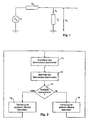
- Fig. 1 the electrical situation of a railway network is shown, as it represents (in a linearized approximation) for a rail vehicle.
- the voltage is supplied by a voltage source U with a fundamental frequency ⁇ o of 16 2/3 Hz, for example.
- the electrical properties of the network are represented by a (complex) network impedance Z N.
- the railway vehicle itself forms a load impedance Z L , and above the railway vehicle there is a voltage U L.
- the impedance values Z L and Z N are frequency-dependent.
- the value of the network impedance Z N depends in particular on the geometry of the rail network and the positions and operating states of the other railway vehicles.
- the load impedance Z L depends on the load with which the railway vehicle travels and how the converter of the railway vehicle is operated. Depending on the operating state, the argument of the load impedance Z L can be between -90 ° and 90 ° or between 90 ° and 270 °. In the former case, the vehicle for the corresponding frequency as "passive”, otherwise referred to as "active".
- the basic principle of the present invention is now the value of the load impedance Z L ( ⁇ ) for one or more frequencies o above the fundamental frequency ⁇ o depending on the network impedance Z N ( ⁇ ) to be chosen so that the stability of the system is guaranteed.
- the railway vehicle must determine the network impedance Z N ( ⁇ ), which is done in a manner described below.
- the system of FIG. 1 is then stable in electrical engineering when it automatically comes to rest after a temporarily applied fault.
- Techniques for testing or calculating the stability of a system according to FIG. 1 are known to the person skilled in the art and need not be discussed further here. For example, the stability criteria according to Hurwitz or Nyquist can be used.
- the value G O L Z N / Z L be calculated.
- the system is then considered unstable if the following two criteria are met: re ( G O L ) ⁇ - 1 .
- ⁇ is a predetermined limit. If conditions (2) and (3) are both satisfied, it is considered that the system may be unstable. In this case, the load impedance Z L ( ⁇ ) is changed by appropriate control of the inverter of the railway vehicle such that the value G OL does not satisfy at least one of the conditions (2) and (3).
- the railway vehicle thus repeatedly measures the impedance Z N of the rail network (step 10) and determines the stability of the system (steps 12, 14). If there is no sufficient stability for an "active" value of the load impedance Z L , the vehicle is operated in "passive" mode (step 16). For this purpose, the load impedance Z L is selected so that the stability criterion used is met. If it appears that sufficient stability is achieved, the vehicle can be operated in "active" mode (step 18). In this way, it is ensured that the instantaneous value of the load impedance Z L is always chosen such that the stability criterion is met, and that, as far as the state of the railway network permits, whenever possible the railway vehicle is operated in the more efficient active mode.
- the load jump can eg by switching on or off of a capacitor or resistor, ie by physical change of the load, or by interfering with the regulation of the locomotive can be achieved.
- the measurement according to equation (4) only leads to realistic results if Z N and Z L do not change during the measurements.
- the test according to FIG. 2 is preferably carried out only for a few harmonic upper frequencies of the network fundamental frequency ⁇ o , for example for the third and fifth harmonics. However, it is also conceivable to test a larger frequency range above the fundamental frequency ⁇ o of the railway network.
Landscapes
- Engineering & Computer Science (AREA)
- Life Sciences & Earth Sciences (AREA)
- Sustainable Development (AREA)
- Sustainable Energy (AREA)
- Power Engineering (AREA)
- Transportation (AREA)
- Mechanical Engineering (AREA)
- Electric Propulsion And Braking For Vehicles (AREA)
- Train Traffic Observation, Control, And Security (AREA)
- Automatic Cycles, And Cycles In General (AREA)
Description
- Die Erfindung betrifft ein Verfahren zum Betrieb eines elektrischen Bahnfahrzeugs gemäss Oberbegriff von Anspruch 1.
- Werden Bahnfahrzeuge mit Umrichter-Antriebstechnik auf einem Bahnnetz betrieben, so kann es zu Stabilitätsproblemen kommen. Ein Hauptgrund dafür ist die Eigenschaft der Bahnfahrzeuge, nicht nur auf der Grundfrequenz sondern auch auf harmonischen Frequenzen Energie in das Netz einzuspeisen. Dies ist dann problematisch, wenn das Netz bei einer dieser harmonischen Frequenzen zu Schwingungen neigt.
- Um Stabilitätsprobleme zu vermeiden, können die Umrichter so ausgestaltet werden, dass sich die Fahrzeuge für alle Frequenzen oberhalb der Grundfrequenz passiv verhalten. Dies führt jedoch zu einem wesentlichen Verlust an Leistungsfähigkeit.
- Zur Lösung dieses Problems wird in J. Holtz und J.O. Krah, "On-line identification of the resonance conditions in the overhead supply line of electric railways" und "Adaptive optimal pulsewidth modulation for the line-side converter of electric locomotives", Proceedings of EPE, Aachen, 1989, pp 385ff bzw. 567ff vorgeschlagen, das Bahnnetz rechnerisch durch ein kompliziertes Modell aus Schwingkreisen zu ersetzen und eine Transferfunktion zu berechnen, die dessen Resonanzen beschreibt. Dies ist jedoch sowohl numerisch als auch messtechnisch aufwendig.
- Es stellt sich deshalb die Aufgabe, ein Verfahren der eingangs genannten Art bereitzustellen, das Stabilitätsprobleme im Bahnnetz auf möglichst einfache Weise vermeidet, ohne dass die Leistungsfähigkeit des Bahnfahrzeugs stark beeinträchtigt wird.
- Diese Aufgabe wird vom Verfahren gemäss Anspruch 1 gelöst.
- Erfindungsgemäss wird also lediglich bei mindestens einer Frequenz die (komplexe) Impedanz des Bahnnetzes vom Bahnfahrzeug aus gemessen und sodann wird die Impedanz des Fahrzeugs nötigenfalls angepasst. Auf diese Weise kann das Fahrzeug zu einer passiven, dämpfenden Last werden, falls das Bahnnetz Gefahr läuft, auf der gegebenen Frequenz instabil zu werden.
- Vorzugsweise wird mit der Fahrzeug- und Netzimpedanz ein Stabilitätskriterium geprüft. Wenn dieses nicht erfüllt ist, so wird die Fahrzeugimpedanz so geändert, dass wieder ein stabiler Zustand erreicht wird. Insbesondere kann zur Stabilisierung des Netzes die Fahrzeugimpedanz derart gewählt werden, dass deren Argument zwischen -90° und 90° liegt.
- In einer besonders vorteilhaften Ausführung wird die Stabilität des Netzes nur für einige wenige Frequenzen, insbesondere für harmonische Frequenzen der Grundfrequenz, geprüft. Durch gezielte Überwachung dieser besonders gefährdeten Frequenzen kann in der Praxis mit geringem Aufwand eine ausreichende Stabilität sichergestellt werden.
- Zur Messung der Netzimpedanz werden vorzugsweise die Spannung und der Strom über dem bzw. durch das Fahrzeug bei unterschiedlichen Fahrzeugimpedanzen gemessen.
- Weitere Vorteile und Anwendungen der Erfindung ergeben sich aus den abhängigen Ansprüchen und aus der nun folgenden Beschreibung anhand der Figuren. Dabei zeigen:
- Fig. 1 ein Ersatzschaltbild für das Bahnnetz mit einem Schienenfahrzeug, und
- Fig. 2 den Entscheidungsablauf im Bahnfahrzeug zur Wahl der Lastimpedanz.
- In Fig. 1 wird die elektrische Situation eines Bahnnetzes gezeigt, wie sie sich (in linearisierter Näherung) für ein Schienenfahrzeug darstellt. Die Spannung wird von einer Spannungsquelle U mit einer Grundfrequenz ωo von z.B. 16 2/3 Hz geliefert. Die elektrischen Eigenschaften des Netzes werden durch eine (komplexe) Netzimpedanz ZN dargestellt. Das Bahnfahrzeug selbst bildet eine Lastimpedanz ZL, und über dem Bahnfahrzeug liegt eine Spannung UL. Die Impedanzwerte ZL und ZN sind frequenzabhängig.
- Der Wert der Netzimpedanz ZN hängt insbesondere von der Geometrie des Bahnnetzes und den Positionen und Betriebszuständen der übrigen Bahnfahrzeuge ab.
- Die Lastimpedanz ZL hängt davon ab, mit welcher Last das Bahnfahrzeug fährt und wie der Umrichter des Bahnfahrzeugs betrieben wird. Je nach Betriebszustand kann das Argument der Lastimpedanz ZL zwischen -90° und 90° oder zwischen 90° und 270° liegen. In ersterem Fall wird das Fahrzeug für die entsprechende Frequenz als "passiv", ansonsten als "aktiv" bezeichnet.
- Das Grundprinzip der vorliegenden Erfindung liegt nun darin, den Wert der Lastimpedanz ZL(ω) für eine oder mehrere Frequenzen o oberhalb der Grundfrequenz ωo abhängig von der Netzimpedanz ZN(ω) so zu wählen, dass die Stabilität des Systems gewährleistet bleibt. Hierzu muss das Bahnfahrzeug die Netzimpedanz ZN(ω) bestimmen, was in einer weiter unten beschriebenen Weise geschieht.
- Aus dem ermittelten Wert der Netzimpedanz ZN(ω) kann sodann ermittelt werden, ob eine gegebene Lastimpedanz ZL(ω) zu Instabilitäten führen kann. Das System nach Fig. 1 ist in elektrotechnischem Sinne dann stabil, wenn es nach einer vorübergehend angelegten Störung automatisch wieder in Ruhe kommt. Techniken zur Prüfung bzw. Berechnung der Stabilität eines Systems gemäss Fig. 1 sind dem Fachmann bekannt und brauchen hier nicht weiter diskutiert zu werden. Beispielsweise können die Stabilitätskriterien nach Hurwitz oder Nyquist beigezogen werden.
- In einer einfachsten Ausführung, welche in praktischen Fällen zu einer sehr konservativen Betriebsweise mit hoher Stabilität führt, kann z.B. der Wert


- Ein Verfahren zur Anpassung der Lastimpedanz ZL(ω) mittels geeigneter Umrichtersteuerung ist z.B. in J. Holtz und J.O. Krah, "Adaptive optimal pulsewidth modulation for the line-side converter of electric locomotives", Proceedings of EPE, Aachen 1989, pp 567 beschrieben.
- Wie aus Fig. 2 ersichtlich, misst das Bahnfahrzeug also wiederholt die Impedanz ZN des Bahnnetzes (Schritt 10) und bestimmt die Stabilität des Systems (Schritt 12, 14). Zeigt sich keine ausreichende Stabilität für einen "aktiven" Wert der Lastimpedanz ZL, so wird das Fahrzeug im "passiven" Modus betrieben (Schritt 16). Hierzu wird die Lastimpedanz ZL so gewählt, dass das verwendete Stabilitätskriterium erfüllt wird. Zeigt es sich, dass eine ausreichende Stabilität erreicht wird, so kann das Fahrzeug im "aktiven" Modus betrieben werden (Schritt 18). Auf diese Weise wird sichergestellt, dass der momentane Wert der Lastimpedanz ZL immer so gewählt ist, dass das Stabilitätskriterium erfüllt ist, und dass, soweit der Zustand des Bahnnetzes dies zulässt, wenn immer möglich das Bahnfahrzeug im effizienteren aktiven Modus betrieben wird.
- Zur Ausführung des Schritts 10 gemäss Fig. 2 muss das Bahnfahrzeug in der Lage sein, die Netzimpedanz ZN zu messen. Dies geschieht dadurch, dass die Spannung UL über dem Bahnfahrzeug und der Strom IL durch das Bahnfahrzeug für zwei verschiedene Werte der Lastimpedanz ZL gemessen werden. Hierzu kann der Umstand ausgenutzt werden, dass die Impedanz ZL auf unterschiedliche Werte eingestellt werden kann. Bezeichnet man die Ströme und Spannungen für einen ersten Wert der Lastimpedanz mit ILA und ULA, diejenigen für einen zweiten Wert der Lastimpedanz (nach einem Lastsprung) mit ILB und ULB, so ergibt sich die Netzimpedanz ZN aus

- Gemessen wird einmal vor und einmal nach dem Lastsprung. Der Lastsprung kann z.B. durch Zu- oder Abschalten eines Kondensators oder Widerstands, also durch physikalische Änderung der Last, oder durch Eingriffe in die Regelung der Lokomotive erreicht werden. Die Messung nach Gleichung (4) führt nur dann zu realistischen Resultaten, wenn sich ZN und ZL während der Messungen nicht verändern.
- Da nur der Zeitverlauf von UL und IL gemessen wird, werden diese Werte jeweils über mindestens eine Periode der Grundfrequenz hinweg abgetastet und gespeichert. Eine anschliessende Fourier-Transformation erlaubt sodann die Bestimmung von ZN(ω) bzw. der Phasen und Amplituden der Ströme und Spannungen.
- Wie eingangs erwähnt, wird die Prüfung gemäss Fig. 2 vorzugsweise nur für einige wenige harmonische Oberfrequenzen der Netz-Grundfrequenz ωo durchgeführt, z.B. für die dritte und fünfte Harmonische. Es ist jedoch auch denkbar, einen grösseren Frequenzbereich oberhalb der Grundfrequenz ωo des Bahnnetzes zu prüfen.
-
- 10 - 18:
- Schritte der Ablaufsteuerung
- GOL:
- open loop gain
- IL:
- Strom durch das Bahnfahrzeug
- ILA, ILB:
- Strom durch das Bahnfahrzeug vor und nach einem Lastsprung
- UL:
- Spannung über dem Bahnfahrzeug
- ULA, ULB:
- Spannung über dem Bahnfahrzeug vor und nach einem Lastsprung
- ZN:
- Netzimpedanz
- ZL:
- Lastimpedanz
- ω:
- Messfrequenz
- ωo:
- Netz-Grundfrequenz
Claims (6)
- Verfahren zum Betrieb eines elektrischen Bahnfahrzeugs mit Rekuperation an einem auf einer Grundfrequenz (ωo) betriebenen Bahnnetz, dadurch gekennzeichnet,
dass vom Bahnfahrzeug auf mindestens einer Frequenz (ω) oberhalb der Grundfrequenz eine Impedanz (ZN) des Bahnnetzes gemessen wird, und
dass die Impedanz (ZL) des Bahnfahrzeugs auf der mindestens einen Frequenz (ω) abhängig von der gemessenen Impedanz (ZN) des Bahnnetzes derart gewählt wird, dass Instabilitäten vermieden werden. - Verfahren nach Anspruch 1, dadurch gekennzeichnet, dass aus der gemessenen Impedanz (ZN) des Bahnnetzes und der momentanen Impedanz (ZL) des Bahnfahrzeugs bei der mindestens einen Frequenz (ω) ein Stabilitätskriterium geprüft wird, und dass, wenn das Stabilitätskriterium nicht erfüllt ist, die Impedanz (ZL) des Fahrzeugs derart geändert wird, dass das Stabilitätskriterium wieder erfüllt wird.
- Verfahren nach einem der vorangehenden Ansprüche, dadurch gekennzeichnet, dass bei drohender Instabilität die Impedanz (ZL) des Bahnfahrzeugs derart geändert wird, dass deren Argument zwischen -90° und 90° liegt.
- Verfahren nach einem der vorangehenden Ansprüche, dadurch gekennzeichnet, dass die Impedanz (ZN) des Bahnnetzes nur auf harmonischen Frequenzen der Grundfrequenz (ωo) gemessen wird.
- Verfahren nach einem der vorangehenden Ansprüche, dadurch gekennzeichnet, dass die Impedanz (ZN) des Bahnnetzes gemessen wird, indem die Spannung (UL) über dem Bahnfahrzeug und der Strom (IL) durch das Bahnfahrzeug für mindestens zwei verschiedene Impedanzen (ZL) des Bahnfahrzeugs gemessen werden.
- Verfahren nach Anspruch 5, dadurch gekennzeichnet, dass die Phase und Amplitude der Spannung (UL) und des Stroms (IL) bei der mindestens einen Frequenz aus einer Fouriertransformation des Zeitverlaufs der Spannung (UL) und des Stroms (IL) ermittelt werden.
Applications Claiming Priority (2)
| Application Number | Priority Date | Filing Date | Title |
|---|---|---|---|
| DE19830425A DE19830425A1 (de) | 1998-07-08 | 1998-07-08 | Verfahren zum Betrieb eines elektrischen Bahnfahrzeugs |
| DE19830425 | 1998-07-08 |
Publications (3)
| Publication Number | Publication Date |
|---|---|
| EP0970841A2 EP0970841A2 (de) | 2000-01-12 |
| EP0970841A3 EP0970841A3 (de) | 2001-12-05 |
| EP0970841B1 true EP0970841B1 (de) | 2006-04-05 |
Family
ID=7873286
Family Applications (1)
| Application Number | Title | Priority Date | Filing Date |
|---|---|---|---|
| EP99810563A Expired - Lifetime EP0970841B1 (de) | 1998-07-08 | 1999-06-28 | Verfahren zum Betrieb eines elektrischen Bahnfahrzeugs |
Country Status (4)
| Country | Link |
|---|---|
| EP (1) | EP0970841B1 (de) |
| AT (1) | ATE322400T1 (de) |
| DE (2) | DE19830425A1 (de) |
| ES (1) | ES2262301T3 (de) |
Family Cites Families (8)
| Publication number | Priority date | Publication date | Assignee | Title |
|---|---|---|---|---|
| AT337307B (de) * | 1973-11-29 | 1977-06-27 | Goerz Electro Gmbh | Schaltung zum messen des innenwiderstandes eines wechselstromnetzes |
| DE3600770A1 (de) * | 1986-01-14 | 1986-11-20 | Eckhard Dipl.-Ing. 7507 Pfinztal Hoffmann | Messverfahren zur ermittlung der betriebsfrequenten netzimpedanzen des hochspannungsnetzes mit hilfe einer transformatorzuschaltung |
| EP0404779B1 (de) * | 1988-03-15 | 1993-06-02 | Siemens Aktiengesellschaft | Verfahren zur stabilisierung eines schwingungsfähigen elektrischen versorgungsnetzes |
| DE3824202A1 (de) * | 1988-07-16 | 1990-01-18 | Asea Brown Boveri | Verfahren zur steuerung eines vierquadrantenstellers |
| DE58907196D1 (de) * | 1989-09-11 | 1994-04-14 | Siemens Ag | Vorrichtung und verfahren zum optimierten betrieb eines an ein netz angeschlossenen stromrichters. |
| US5300876A (en) * | 1990-05-11 | 1994-04-05 | Kabushiki Kaisha Toshiba | Power system stabilizer estimating a power system impedance |
| DE4100646C2 (de) * | 1991-01-11 | 1995-08-24 | Licentia Gmbh | Verfahren und Anordnung zum Schutz von Distantschutzeinrichtungen vor unerwünschter Auslösung während transierter Leistungspendelungen |
| DE4434378C1 (de) * | 1994-09-15 | 1996-05-09 | Aeg Schienenfahrzeuge | Verfahren zur Regelung eines als Netzstromrichter fungierenden Vierquadrantenstellers |
-
1998
- 1998-07-08 DE DE19830425A patent/DE19830425A1/de not_active Withdrawn
-
1999
- 1999-06-28 EP EP99810563A patent/EP0970841B1/de not_active Expired - Lifetime
- 1999-06-28 AT AT99810563T patent/ATE322400T1/de not_active IP Right Cessation
- 1999-06-28 DE DE59913293T patent/DE59913293D1/de not_active Expired - Fee Related
- 1999-06-28 ES ES99810563T patent/ES2262301T3/es not_active Expired - Lifetime
Also Published As
| Publication number | Publication date |
|---|---|
| EP0970841A3 (de) | 2001-12-05 |
| DE59913293D1 (de) | 2006-05-18 |
| ES2262301T3 (es) | 2006-11-16 |
| EP0970841A2 (de) | 2000-01-12 |
| ATE322400T1 (de) | 2006-04-15 |
| DE19830425A1 (de) | 2000-01-13 |
Similar Documents
| Publication | Publication Date | Title |
|---|---|---|
| EP2130294B1 (de) | Verfahren und vorrichtung zum betrieb einer doppeltgespeisten asynchronmaschine bei transienten netzspannungsänderungen | |
| WO2013083850A2 (de) | Prüfeinrichtung zur durchführung von funktionstests an energieerzeugern | |
| EP3375655A1 (de) | Technik zur isolationsüberwachung in fahrzeugen | |
| EP0491691B1 (de) | Verfahren und vorrichtung zur erfassung von resonanzmessgrössen eines an einem stromrichter angeschlossenen netzes | |
| EP2140278B1 (de) | Verfahren zum ermitteln elektrischer parameter eines streckenabschnitts einer magnetschwebebahn | |
| WO1996009685A1 (de) | Verfahren zur regelung eines als netzstromrichter fungierenden vierquadrantenstellers | |
| EP0970841B1 (de) | Verfahren zum Betrieb eines elektrischen Bahnfahrzeugs | |
| EP0596895A1 (de) | Verfahren und einrichtung zur elektrischen kurzschlussprüfung und -ortung für leitungen, insbesondere für fahrleitungen elektrischer bahnen. | |
| EP4005086B1 (de) | Steuereinrichtung, wechselrichter, anordnung mit einem wechselrichter und einer elektrischen maschine, verfahren zum betreiben eines wechselrichters sowie computerprogramm | |
| EP3696964A1 (de) | Prädikative wartung des eingangs- und zwischenkreises von umrichtern und einspeiseleistungsteilen | |
| EP4096079B1 (de) | Anordnung zur funktionsprüfung von kondensatoren einer filtereinrichtung eines fahrzeugs | |
| EP1541441B1 (de) | Verfahren zur Bestimmung der Wirkleistung eines Drehstrommotors und elektronische Weichensteuerung | |
| DE102022133309A1 (de) | Testanordnung und verfahren zur emulation der phasen-ströme eines elektromotors für ein prüfen eines leistungs-elektronischen steuergeräts | |
| EP2685581A1 (de) | Versorgung eines Schienenfahrzeugs mit elektrischer Energie über eine abgeschirmte Energieversorgungsleitung | |
| EP0494137B1 (de) | Verfahren und vorrichtung zum optimierten betrieb eines pulswechselrichters am netz | |
| WO1996008862A1 (de) | Verfahren zur regelung eines als netzstromrichter fungierenden vierquadrantenstellers | |
| EP1017157B1 (de) | Verfahren zur Regelung eines nichtharmonischen Anteils im Netzstrom eines netzseitigen Stromrichters und Vorrichtung zur Durchführung des Verfahrens | |
| DE102022210180A1 (de) | Überwachung der korrekten Funktion eines Hauptschalters eines Schienenfahrzeugs | |
| EP1079493B1 (de) | Verfahren zur Oberschwingungskompensation in elektrischen Versorgungsnetzen | |
| EP3442106A1 (de) | Oberspannungssensorfreie antriebsvorrichtung | |
| DE102019118562A1 (de) | Verfahren und Vorrichtung zur Kompensation von Störgrößen | |
| EP3741022A1 (de) | Verfahren und vorrichtung zum regeln einer elektrischen spannung | |
| DE102018215594A1 (de) | Verfahren zum Überwachen eines Saugkreises eines Stromrichtersystems | |
| DE102018251776A1 (de) | Fahrzeug | |
| DE102022210181A1 (de) | Selbsttestende Messeinrichtung |
Legal Events
| Date | Code | Title | Description |
|---|---|---|---|
| PUAI | Public reference made under article 153(3) epc to a published international application that has entered the european phase |
Free format text: ORIGINAL CODE: 0009012 |
|
| AK | Designated contracting states |
Kind code of ref document: A2 Designated state(s): AT BE CH CY DE DK ES FI FR GB GR IE IT LI LU MC NL PT SE |
|
| AX | Request for extension of the european patent |
Free format text: AL;LT;LV;MK;RO;SI |
|
| RAP1 | Party data changed (applicant data changed or rights of an application transferred) |
Owner name: DAIMLERCHRYSLER AG |
|
| RAP1 | Party data changed (applicant data changed or rights of an application transferred) |
Owner name: DAIMLERCHRYSLER RAIL SYSTEMS GMBH |
|
| PUAL | Search report despatched |
Free format text: ORIGINAL CODE: 0009013 |
|
| AK | Designated contracting states |
Kind code of ref document: A3 Designated state(s): AT BE CH CY DE DK ES FI FR GB GR IE IT LI LU MC NL PT SE |
|
| AX | Request for extension of the european patent |
Free format text: AL;LT;LV;MK;RO;SI |
|
| 17P | Request for examination filed |
Effective date: 20020604 |
|
| AKX | Designation fees paid |
Free format text: AT BE CH CY DE FR IT LI |
|
| RBV | Designated contracting states (corrected) |
Designated state(s): AT BE CH CY DE DK ES FI FR GB GR IE IT LI LU MC NL PT SE |
|
| GRAP | Despatch of communication of intention to grant a patent |
Free format text: ORIGINAL CODE: EPIDOSNIGR1 |
|
| RAP1 | Party data changed (applicant data changed or rights of an application transferred) |
Owner name: BOMBARDIER TRANSPORTATION GMBH |
|
| GRAS | Grant fee paid |
Free format text: ORIGINAL CODE: EPIDOSNIGR3 |
|
| GRAA | (expected) grant |
Free format text: ORIGINAL CODE: 0009210 |
|
| AK | Designated contracting states |
Kind code of ref document: B1 Designated state(s): AT BE CH CY DE DK ES FI FR GB GR IE IT LI LU MC NL PT SE |
|
| PG25 | Lapsed in a contracting state [announced via postgrant information from national office to epo] |
Ref country code: NL Free format text: LAPSE BECAUSE OF FAILURE TO SUBMIT A TRANSLATION OF THE DESCRIPTION OR TO PAY THE FEE WITHIN THE PRESCRIBED TIME-LIMIT Effective date: 20060405 Ref country code: IE Free format text: LAPSE BECAUSE OF FAILURE TO SUBMIT A TRANSLATION OF THE DESCRIPTION OR TO PAY THE FEE WITHIN THE PRESCRIBED TIME-LIMIT Effective date: 20060405 Ref country code: GB Free format text: LAPSE BECAUSE OF FAILURE TO SUBMIT A TRANSLATION OF THE DESCRIPTION OR TO PAY THE FEE WITHIN THE PRESCRIBED TIME-LIMIT Effective date: 20060405 Ref country code: FI Free format text: LAPSE BECAUSE OF FAILURE TO SUBMIT A TRANSLATION OF THE DESCRIPTION OR TO PAY THE FEE WITHIN THE PRESCRIBED TIME-LIMIT Effective date: 20060405 |
|
| REG | Reference to a national code |
Ref country code: GB Ref legal event code: FG4D Free format text: NOT ENGLISH |
|
| REG | Reference to a national code |
Ref country code: CH Ref legal event code: EP |
|
| REG | Reference to a national code |
Ref country code: IE Ref legal event code: FG4D Free format text: LANGUAGE OF EP DOCUMENT: GERMAN |
|
| REF | Corresponds to: |
Ref document number: 59913293 Country of ref document: DE Date of ref document: 20060518 Kind code of ref document: P |
|
| PG25 | Lapsed in a contracting state [announced via postgrant information from national office to epo] |
Ref country code: MC Free format text: LAPSE BECAUSE OF NON-PAYMENT OF DUE FEES Effective date: 20060630 Ref country code: BE Free format text: LAPSE BECAUSE OF NON-PAYMENT OF DUE FEES Effective date: 20060630 |
|
| PG25 | Lapsed in a contracting state [announced via postgrant information from national office to epo] |
Ref country code: SE Free format text: LAPSE BECAUSE OF FAILURE TO SUBMIT A TRANSLATION OF THE DESCRIPTION OR TO PAY THE FEE WITHIN THE PRESCRIBED TIME-LIMIT Effective date: 20060705 Ref country code: DK Free format text: LAPSE BECAUSE OF FAILURE TO SUBMIT A TRANSLATION OF THE DESCRIPTION OR TO PAY THE FEE WITHIN THE PRESCRIBED TIME-LIMIT Effective date: 20060705 |
|
| PG25 | Lapsed in a contracting state [announced via postgrant information from national office to epo] |
Ref country code: PT Free format text: LAPSE BECAUSE OF FAILURE TO SUBMIT A TRANSLATION OF THE DESCRIPTION OR TO PAY THE FEE WITHIN THE PRESCRIBED TIME-LIMIT Effective date: 20060905 |
|
| NLV1 | Nl: lapsed or annulled due to failure to fulfill the requirements of art. 29p and 29m of the patents act | ||
| GBV | Gb: ep patent (uk) treated as always having been void in accordance with gb section 77(7)/1977 [no translation filed] |
Effective date: 20060405 |
|
| ET | Fr: translation filed | ||
| REG | Reference to a national code |
Ref country code: IE Ref legal event code: FD4D |
|
| REG | Reference to a national code |
Ref country code: ES Ref legal event code: FG2A Ref document number: 2262301 Country of ref document: ES Kind code of ref document: T3 |
|
| PLBE | No opposition filed within time limit |
Free format text: ORIGINAL CODE: 0009261 |
|
| STAA | Information on the status of an ep patent application or granted ep patent |
Free format text: STATUS: NO OPPOSITION FILED WITHIN TIME LIMIT |
|
| 26N | No opposition filed |
Effective date: 20070108 |
|
| PG25 | Lapsed in a contracting state [announced via postgrant information from national office to epo] |
Ref country code: AT Free format text: LAPSE BECAUSE OF NON-PAYMENT OF DUE FEES Effective date: 20060628 |
|
| BERE | Be: lapsed |
Owner name: BOMBARDIER TRANSPORTATION G.M.B.H. Effective date: 20060630 |
|
| PG25 | Lapsed in a contracting state [announced via postgrant information from national office to epo] |
Ref country code: GR Free format text: LAPSE BECAUSE OF FAILURE TO SUBMIT A TRANSLATION OF THE DESCRIPTION OR TO PAY THE FEE WITHIN THE PRESCRIBED TIME-LIMIT Effective date: 20060706 |
|
| PG25 | Lapsed in a contracting state [announced via postgrant information from national office to epo] |
Ref country code: LU Free format text: LAPSE BECAUSE OF NON-PAYMENT OF DUE FEES Effective date: 20060628 |
|
| PG25 | Lapsed in a contracting state [announced via postgrant information from national office to epo] |
Ref country code: CY Free format text: LAPSE BECAUSE OF FAILURE TO SUBMIT A TRANSLATION OF THE DESCRIPTION OR TO PAY THE FEE WITHIN THE PRESCRIBED TIME-LIMIT Effective date: 20060405 |
|
| PGFP | Annual fee paid to national office [announced via postgrant information from national office to epo] |
Ref country code: ES Payment date: 20090623 Year of fee payment: 11 |
|
| PGFP | Annual fee paid to national office [announced via postgrant information from national office to epo] |
Ref country code: IT Payment date: 20090624 Year of fee payment: 11 Ref country code: FR Payment date: 20090615 Year of fee payment: 11 |
|
| PGFP | Annual fee paid to national office [announced via postgrant information from national office to epo] |
Ref country code: CH Payment date: 20090617 Year of fee payment: 11 |
|
| PGFP | Annual fee paid to national office [announced via postgrant information from national office to epo] |
Ref country code: DE Payment date: 20090622 Year of fee payment: 11 |
|
| REG | Reference to a national code |
Ref country code: CH Ref legal event code: PL |
|
| REG | Reference to a national code |
Ref country code: FR Ref legal event code: ST Effective date: 20110228 |
|
| PG25 | Lapsed in a contracting state [announced via postgrant information from national office to epo] |
Ref country code: IT Free format text: LAPSE BECAUSE OF NON-PAYMENT OF DUE FEES Effective date: 20100628 |
|
| PG25 | Lapsed in a contracting state [announced via postgrant information from national office to epo] |
Ref country code: DE Free format text: LAPSE BECAUSE OF NON-PAYMENT OF DUE FEES Effective date: 20110101 Ref country code: LI Free format text: LAPSE BECAUSE OF NON-PAYMENT OF DUE FEES Effective date: 20100630 Ref country code: CH Free format text: LAPSE BECAUSE OF NON-PAYMENT OF DUE FEES Effective date: 20100630 |
|
| PG25 | Lapsed in a contracting state [announced via postgrant information from national office to epo] |
Ref country code: FR Free format text: LAPSE BECAUSE OF NON-PAYMENT OF DUE FEES Effective date: 20100630 |
|
| REG | Reference to a national code |
Ref country code: ES Ref legal event code: FD2A Effective date: 20110718 |
|
| PG25 | Lapsed in a contracting state [announced via postgrant information from national office to epo] |
Ref country code: ES Free format text: LAPSE BECAUSE OF NON-PAYMENT OF DUE FEES Effective date: 20110706 |
|
| PG25 | Lapsed in a contracting state [announced via postgrant information from national office to epo] |
Ref country code: ES Free format text: LAPSE BECAUSE OF NON-PAYMENT OF DUE FEES Effective date: 20100629 |