EP0970632B1 - Reissverschluss - Google Patents
Reissverschluss Download PDFInfo
- Publication number
- EP0970632B1 EP0970632B1 EP99304231A EP99304231A EP0970632B1 EP 0970632 B1 EP0970632 B1 EP 0970632B1 EP 99304231 A EP99304231 A EP 99304231A EP 99304231 A EP99304231 A EP 99304231A EP 0970632 B1 EP0970632 B1 EP 0970632B1
- Authority
- EP
- European Patent Office
- Prior art keywords
- ribbon
- web
- interlocking member
- profile
- slider
- Prior art date
- Legal status (The legal status is an assumption and is not a legal conclusion. Google has not performed a legal analysis and makes no representation as to the accuracy of the status listed.)
- Expired - Lifetime
Links
- 229920003023 plastic Polymers 0.000 claims description 11
- 239000004033 plastic Substances 0.000 claims description 11
- 238000004519 manufacturing process Methods 0.000 claims description 9
- 238000000034 method Methods 0.000 claims description 5
- 239000004698 Polyethylene Substances 0.000 description 3
- -1 polyethylene Polymers 0.000 description 3
- 229920000573 polyethylene Polymers 0.000 description 3
- 238000010586 diagram Methods 0.000 description 2
- 239000000463 material Substances 0.000 description 2
- 238000007789 sealing Methods 0.000 description 2
- 230000008878 coupling Effects 0.000 description 1
- 238000010168 coupling process Methods 0.000 description 1
- 238000005859 coupling reaction Methods 0.000 description 1
- 238000004806 packaging method and process Methods 0.000 description 1
Images


Classifications
-
- B—PERFORMING OPERATIONS; TRANSPORTING
- B65—CONVEYING; PACKING; STORING; HANDLING THIN OR FILAMENTARY MATERIAL
- B65D—CONTAINERS FOR STORAGE OR TRANSPORT OF ARTICLES OR MATERIALS, e.g. BAGS, BARRELS, BOTTLES, BOXES, CANS, CARTONS, CRATES, DRUMS, JARS, TANKS, HOPPERS, FORWARDING CONTAINERS; ACCESSORIES, CLOSURES, OR FITTINGS THEREFOR; PACKAGING ELEMENTS; PACKAGES
- B65D33/00—Details of, or accessories for, sacks or bags
- B65D33/16—End- or aperture-closing arrangements or devices
- B65D33/25—Riveting; Dovetailing; Screwing; using press buttons or slide fasteners
- B65D33/2508—Riveting; Dovetailing; Screwing; using press buttons or slide fasteners using slide fasteners with interlocking members having a substantially uniform section throughout the length of the fastener; Sliders therefor
- B65D33/2541—Riveting; Dovetailing; Screwing; using press buttons or slide fasteners using slide fasteners with interlocking members having a substantially uniform section throughout the length of the fastener; Sliders therefor characterised by the slide fastener, e.g. adapted to interlock with a sheet between the interlocking members having sections of particular shape
-
- A—HUMAN NECESSITIES
- A44—HABERDASHERY; JEWELLERY
- A44B—BUTTONS, PINS, BUCKLES, SLIDE FASTENERS, OR THE LIKE
- A44B19/00—Slide fasteners
- A44B19/10—Slide fasteners with a one-piece interlocking member on each stringer tape
- A44B19/16—Interlocking member having uniform section throughout the length of the stringer
-
- A—HUMAN NECESSITIES
- A44—HABERDASHERY; JEWELLERY
- A44B—BUTTONS, PINS, BUCKLES, SLIDE FASTENERS, OR THE LIKE
- A44B19/00—Slide fasteners
- A44B19/24—Details
- A44B19/26—Sliders
- A44B19/267—Sliders for slide fasteners with edges of stringers having uniform section throughout the length thereof
-
- Y—GENERAL TAGGING OF NEW TECHNOLOGICAL DEVELOPMENTS; GENERAL TAGGING OF CROSS-SECTIONAL TECHNOLOGIES SPANNING OVER SEVERAL SECTIONS OF THE IPC; TECHNICAL SUBJECTS COVERED BY FORMER USPC CROSS-REFERENCE ART COLLECTIONS [XRACs] AND DIGESTS
- Y10—TECHNICAL SUBJECTS COVERED BY FORMER USPC
- Y10T—TECHNICAL SUBJECTS COVERED BY FORMER US CLASSIFICATION
- Y10T156/00—Adhesive bonding and miscellaneous chemical manufacture
- Y10T156/10—Methods of surface bonding and/or assembly therefor
- Y10T156/1052—Methods of surface bonding and/or assembly therefor with cutting, punching, tearing or severing
- Y10T156/1084—Methods of surface bonding and/or assembly therefor with cutting, punching, tearing or severing of continuous or running length bonded web
- Y10T156/1087—Continuous longitudinal slitting
Definitions
- Slide zippers have different requirements than traditional interlocking zippers which are opened and closed directly by the hands of the user.
- Slide zippers for use with plastic bags are well known in the reclosable fastener art. Examples of conventional slide zippers can be found in US-A-5,007,143, US-A-5,008,971, US-A-5,131,121 and US-A-5,664,299.
- FR-A-1564039 shows a slide zipper assembly in which an inverted-shaped slider is mounted directly on interlocking members including integral depending flanges to which opposite sides of a bag are attached.
- US-A-2916197 shows a bag which is divided into separate compartments by either sealing its opposite sides together or by coupling them together with interlocking members. Finger gripping tabs are provided on the outside of the bags to enable a user to grip opposite sides of the bag and thereby open the seal or the interlocked members to mix components in the separate compartments together.
- a slide zipper assembly comprising: an interlocking zipper having a first profile a second profile and a slider disposed for movement along the zipper; said first profile including a ribbon, a web attached to said ribbon, and an interlocking member attached to said web, said ribbon having a free edge unattached to said web; said second profile including a ribbon, a web attached to said ribbon, and an interlocking member attached to said web engageable with said first profile interlocking member, said ribbon having a free edge unattached to said web; said slider including a top and first and second arms depending from said top, each of said arms having a hooked end directed towards the other arm; wherein said slider is positioned on said zipper so that said first and second slider arms enclose said first and second profile ribbons, respectively, and so that said first and second slider arm hooked ends hook around said first and second profile ribbon free edges, respectively, so that each of said hooked ends is positioned between a ribbon and its attached web.
- the hooked end of the slider hold the slider in place and prevent the slider from being pulled off the zipper.
- the profiles are sealed together at either end so that when the slider reaches the ends of the zipper the hooked ends of the slider arms will contact the sealed area and be prevented from moving any further.
- the slider has an opening end and a closing end. At the closing end the slider arm inner walls are sufficiently close to one another to press the two profiles into engagement when the slider is moved in the closing direction (i.e. opposite to the closing end).
- the interlocking members each have a pair of hooked arms.
- the hooks on the first interlocking member are oriented outwardly with respect to each other and are adapted to engage the hooks of the second interlocking member, which are oriented inwardly with respect to each other.
- there is a contoured separator blade which extends downwardly from the top of the slider and which is engageable with the top hooked arm of the first interlocking member.
- the separator blade When the slider is moved in the opening direction, the separator blade disengages the top hooked arms of the interlocking members and a force component on the top hooked arm of the first interlocking member urges the top of the f irst profile away from the second profile.
- the inner walls of the slider arms are further apart than at the closing end such that the slider arms do not force the profiles into engagement.
- the opening end of the slider may also be provided with a cavity or recess to facilitate lateral movement of the first profile.
- the hooked end on the first slider arm may engage the bottom of the ribbon portion of the first profile and lift the same so that the bottom hooked arms of the two interlocking members also disengage.
- the combined actions of the separator blade and the hooked end on the first slider arm thus serve to first disengage the top hooked arm of the first interlocking member from the top hooked arm of the second interlocking member, then move the first profile away from the second profile, and then lift the bottom hooked arm of the first interlocking member out of engagement with the bottom hooked arm of the second interlocking member to thereby free second slider arm could force the second profile downwardly out of engagement with the first profile.
- an interlocking zipper comprising:
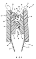
- FIG 1 shows a cross sectional view of a zipper 10 in accordance with the present invention.
- the zipper 10 is comprised of a first profile 12 and a second profile 14.
- the zipper 10 is disposable along the opening of a plastic bag 82, as shown in Figures 5 and 6.
- the bag 82 will be assumed to be oriented with its opening on top, as depicted in Figures 5 and 6.
- the first profile 12 includes a ribbon 16, a web 18 attached to the ribbon 16, and an interlocking member 20 attached to the web 18.
- the ribbon 16 has a free end 17 which is not attached to the web 18 and an end 19 which is attached to the web.
- the second profile 14 includes a ribbon 22, a web 24 attached to the ribbon 22, and an interlocking member 26 attached to the web 24 which mates with the interlocking member 20 of the first profile 12.
- the ribbon 22 has a free end 23 which is not attached to the web 24 and an end 27 which is attached to the web.
- the interlocking members, ribbons and webs of each profile are separately extruded from a plastic commonly used in the reclosable packaging industry, such as polyethylene, and then fused together to form the integrated zipper 10.
- the profile webs 18, 24 provide a means by which the zipper may be sealed to a plastic bag and also provide a means by which the zipper may be guided in an machine.
- the profile ribbons interact with the slider to hold the slider on the zipper and provide a path along which the slider may slide.
- the first interlocking member 20 has a base 25 and top and bottom hooked arms 28, 30 extending from the base 25 toward the second profile 14.
- the top hooked arm 28 and the bottom hooked arm 30 of the first interlocking member 20 have hooked ends 32 and 34 which are directed away from each other.
- the hooked end 32 of the top hooked arm 28 is oriented upwardly while the hooked end 34 of the bottom hooked arm 30 is oriented downwardly.
- the top hooked arm 28 is longer and thinner than the bottom hooked arm 30.
- the top hooked arm 28 is thus more flexible than the bottom hooked arm 30, thereby providing for ease of opening of the zipper 10 from the outside of a bag employing the zipper 10.
- the bottom hooked arm 30 is shorter and thicker than top hooked arm 28, and thus less flexible, the internal opening force will be greater.
- the second interlocking member 26 likewise has a base 36 and top and b6ttom hooked arms 38, 40.
- the top hooked arm 38 and bottom hooked arm 40 have hooked ends 42, 44 which are directed towards each other and positioned and sized to engage the hooked ends 32, 34 of the first profile hooked arms.
- the top hooked arm 38 has a downwardly oriented hooked end 42 which is engageable with the hooked end 32 of the top hooked arm 28 of the first interlocking member 20 and the bottom hooked arm 40 has an upwardly oriented hooked end 44 which is engageable with the hooked end 34 of the bottom hooked arm 30 of the first interlocking member 20.
- This two-arm configuration of the zipper 10 provides a relatively leak proof seal.
- the second interlocking member 26 may also have an inwardly directed wedge or bump 46 which is located between the top hooked arm 38 and the bottom hooked arm 40 and which aids in guiding the interlocking members into and out of engagement.
- a first apparatus 50 for manufacturing the zipper is shown in Figure 2.
- the first apparatus 50 comprises three rolls 52, 54, 56 driven by a belt 58, two pinch rolls 60, 62, and three extruders 64, 66, 68.
- the first extruder 64 extrudes a ribbon of material 70, such as polyethylene, into a groove on the belt 58.
- the first pinch roll 60 fits into the belt groove and ensures that the ribbon 70 is extruded into the groove. While no specific dimension for the ribbon 70 is required, dimensions of approximately 0.020" thick by 0.375" wide (0.5 by 9.4 mm) is preferred.
- the second extruder 66 extrudes a web of material 72, such as polyethylene, having preferred dimensions of approximately 0.002" thick by 1.375" wide (0.05 by 34 mm) on top of the second roll 54 and the ribbon 70.
- the ribbon 70 is recessed in the belt groove, and the second pinch roll 62 deflects the web 72 into the groove and onto the center of the ribbon 70, causing the ribbon 70 and the web to become fused together.
- the width of the second pinch roll 62 is less than the width of the ribbon 70 such that the ribbon 70 does not become fused to the web 72 at its edges.
- the third extruder 68 then extrudes the interlocking members 20, 26 in an uninterlocked condition onto the portion of the web 72 which was fused to the ribbon 70.
- the result of this process is shown in Figure 3.
- the ribbon 70 is centrally fused to the web 72, and the interlocking member 20, 26 are fused to the portion of the web 72 which is fused to the ribbon 70.
- the ribbon 70 is not fused to the web 72 at its edges 74. This will aid in keeping the slider on the zipper, as discussed more fully below.
- the-ribbon 70 and web 72 are slit along the centerline to form the two separate profiles 12, 14, which may then be interlocked as shown in Figure 1.
- a second apparatus 76 for manufacturing the zipper is shown in Figure 4.
- the second apparatus 76 differs from the first apparatus 50 in that a single roll 78 is used, instead of a belt in combination with three rolls.
- the ribbon 70 is extruded into a groove in the roll 78. This is facilitated by pinch roll 60.
- the web 72 is then extruded onto-the roll 76 and the ribbon 70, the second pinch roll 62 fusing the two together.
- the interlocking members 20, 26 are extruded onto the web portion 72 fused to the ribbon 70, resulting in the zipper of Figure 3.
- the zipper is then slit to arrive at the zipper of Figure 1.
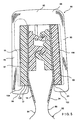
- Figures 5 and 6 illustrate how the zipper 10 cooperates with a slider 80.
- the zipper 10 is attached to a plastic bag 82 by sealing the zipper webs 18, 24 to opposing bag walls 84, 86.
- the slider 80 straddles the zipper 10 enclosing the profile ribbons 16, 22.
- the slider 80 has a closing end 88 and an opening end 90.
- the slider closing end is shown in Figure 5 and the slider opening end is shown in Figure 6.
- the interlocking members 20, 26 are engaged by the slider.
- the interlocking members are disengaged by the slider.
- the profiles are sealed to each other at both ends to ensure that the slider cannot be pulled off the zipper in a slidewardly direction.
- the slider 80 has a top portion 92 , a first arm 94 and a second arm 96. Enough clearance is provided between the slider top 92 and the zipper so that the slider can be inserted over the zipper and seated thereupon as shown in Figures 5 and 6.
- the first arm 94 has an inner side 97 and an inwardly directed hooked end 98.
- the second arm 96 has an inner side 100 and an inwardly directed hooked end 102.
- the inner sides 97, 100 of the slider arms are tapered from the opening end 90 towards the closing end 88 so that at the closing end 88 the arms are sufficiently close to press the profiles into engagement with each other.
- the hooked ends 98, 102 of the slider arms hook around the free ends 17, 23 of the profile ribbons 16, 22 such that they become positioned between the ribbons 16, 22 and webs 18, 24. In this manner the slider 80 is held in place on the zipper 10 and cannot be pulled off the zipper 10 without destroying the zipper 10. It is for this reason that during the zipper manufacturing process the ribbon edges 74 are not sealed to the web 72.
- a top surface 104 of first slider arm hooked end 98 mates with a bottom surface 106 of the first profile ribbon 16, imparting a generally upward force thereto. This force, as discussed below, plays a role in the opening and closing action of the slider 80.
- the zipper 10 is captured between the inner sides 97, 100 of the slider arms 94, 96.
- the slider arm hooked ends 98, 102 hold the slider in place and ensure that it cannot be pulled off the zipper.
- the inner sides 97, 100 of the slider arms 94, 96 are sufficiently close at the closing end so that when the slider 80 is moved in the closing direction, the inner sides 97, 100 of the slider arms 94, 96 press against the profile ribbons 16, 22, thereby effecting engagement of the profiles 12, 14.
- Figure 6 shows the opening end 90 of the slider 80.
- the inner sides 97, 100 of the slider arms 94, 96 are sufficiently far apart so as to not impart a closing force to the profiles 12, 14 and to allow for disengagement of the profiles 12, 14.
- a separator blade 108 extends downwardly from the slider top 92 as shown.
- the inner side 97 of first slider arm 94 is contoured to define a cavity 110 which extends upwardly into the top 92.
- the separator blade 108 is positioned so that when the slider 80 is moved in the opening direction, the separator blade 108 will deflect the top hooked arm 28 of the first interlocking member 20 downwardly and out of engagement With the top hooked arm 38 of the second interlocking member 26. A component of the force on the top hooked arm 28 of the first interlocking member 20 will also direct the now disengaged first profile 12 sideways and into the cavity 110.
- the separator blade 108 deflects the top hooked arm 28 of the first interlocking member 20 downwardly and out of engagement with the top hooked arm 38 of the second interlocking member 26 until the top hooked arm 28 engages the bump 46.
- the bump 46 provides a camming surface for the top hooked arm 28 as a component of the force exerted by the separator blade 108 acts on the top hooked arm 28 to urge the first profile 12 away from the second profile 14. Simultaneously, the top surface 104 of the first slider arm hooked end 98 pushes the first ribbon bottom surface 106 upwardly.
- This upward deflection in combination with the outward deflection of the first profile 12 by the separator blade 108 disengages the bottom hooked arm 30 of the first interlocking member 20 from the bottom hooked arm 40 of the second interlocking member 26 and moves the first profile 12 up and into the cavity 110.
- means could be provided to force the second profile downwardly out of engagement with the first profile, as opposed to forcing the first profile upwardly.
- the-combined action of the separator blade 108 and first slider arm hooked end 98 on the first profile serves to open the zipper as the slider is moved in the opening direction. Movement of the slider in the closing direction causes the slider arms to force the profiles into engagement.
Landscapes
- Engineering & Computer Science (AREA)
- Mechanical Engineering (AREA)
- Slide Fasteners (AREA)
- Making Paper Articles (AREA)
- Bag Frames (AREA)
- Two-Way Televisions, Distribution Of Moving Picture Or The Like (AREA)
Claims (10)
- Gleitreißverschlußvorrichtung (10) mit: einem verriegelnden Reißverschluß mit einem ersten Profil (12), einem zweiten Profil (14) und einem zwecks Bewegung längs dem Reißverschluß angeordneten Schieber (80); wobei das erste Profil (12) ein Band (16), eine an dem Band (16) befestigte Rippe (18) und ein an der Rippe (18) befestigtes Verriegelungselement (20) umfaßt, wobei das Band (16) einen freien, nicht an der Rippe (18) befestigten Rand (17) aufweist; das zweite Profil (14) ein Band (22), eine an dem Band (22) befestigte Rippe (24) und ein Verriegelungselement (26) umfaßt, das an der mit dem ersten profilierten Verriegelungselement (20) in Eingriff bringbaren Rippe (24) befestigt ist, wobei das Band (22) einen freien, nicht an der Rippe (24) befestigten Rand (23) aufweist; der Schieber (80) ein Oberteil (92) und von dem Oberteil (92) herabhängende erste und zweite Arme (94, 96) umfaßt,
wobei jeder der Arme (94, 96) ein zu dem anderen Arm hin gerichtetes, hakenförmiges Ende (98, 102) aufweist; wobei der Schieber (80) so an dem Reißverschluß positioniert ist, daß die ersten und zweiten Schieberarme (94, 96) die ersten und zweiten profilierten Bänder (16, 22) jeweils so umschließen, daß sich die hakenförmi-gen Enden (98, 102) der ersten und zweiten Schieberarme jeweils um die ersten und zweiten freien Ränder (17, 23) der profilierten Bänder herum verhaken, so daß jedes der hakenförmigen Enden (98, 102) zwischen einem Band (16, 22) und seiner befestigten Rippe (18, 24) positioniert wird. - Gleitreißverschlußvorrichtung nach Anspruch 1, wobei jede der Rippen (18, 24) über den freien Rand ihres befestigten Bandes (16, 22) hinausragt.
- Gleitreißverschlußvorrichtung nach Anspruch 1 oder 2, wobei das erste profilierte Verriegelungselement (20) eine Basis (25) mit einem oberen Arm (28) und einem unteren Arm (30) umfaßt, die von der Basis (25) ausgehen, wobei jeder der Arme (28, 30) ein von dem anderen Arm weg gerichtetes hakenförmiges Ende (32, 34) aufweist;
wobei das zweite profilierte Verriegelungselement (26) eine Basis (36) mit einem oberen Arm (38) und einem unteren Arm (40) umfaßt, die von der Basis (36) ausgehen, wobei jeder der zweiten profilierten Verriegelungarme (38, 40) ein zu dem anderen Arm hin gerichtetes hakenförmiges Ende (42, 44) aufweist; und
wobei sich die Arme (28, 30) des ersten profilierten Verriegelungselementes (26) zwischen den Armen (38, 40) des zweiten profilierten Verriegelungselementes (26) positionieren, wobei die hakenförmigen Enden (32, 34, 42, 44) der Arme des ersten und des zweiten profilierten Verriegelungselements in Eingriff stehen, wenn sich der Reißverschluß in geschlossener Position befindet. - Gleitreißverschlußvorrichtung nach Anspruch 3, wobei der Schieber (80) weiter eine sich von dem Oberteil (92) des Schiebers nach unten erstreckende Trennvorrichtung (108) umfaßt, wobei die Trennvorrichtung (108) so angeordnet ist, daß sie mit dem oberen Arm (28) des ersten profilierten Verriegelungselementes in Eingriff kommt, um ihn zu dem unteren Arm (30) des ersten profilierten Verriegelungselementes hin zu biegen, wodurch das hakenförmige Ende (32) des oberen Arms (28) des ersten profilierten Verriegelungselementes außer Eingriff mit dem hakenförmigen Ende (42) des oberen Arms (38) des zweiten profilierten Verriegelungselementes kommt.
- Gleitreißverschlußvorrichtung nach einem der vorhergehenden Ansprüche,
wobei die Rippe (18) dünner als das Band (16) ist. - Verriegelnder Reißverschluß, mit:wobei das zweite Verriegelungselement (26) mit dem ersten Verriegelungselement (20) in Eingriff bringbar ist.einem Band (70) mit einander gegenüberliegenden Rändern;einer Rippe (72), die dünner als das Band (70) ist und nur an einem Bereich zwischen den Bandrändern an dem Band (70) befestigt ist, um die freien Ränder des Bandes (70) zwecks Zusammenwirken mit einem Schieber an der Rippe (72) unbefestigt zu belassen;einem ersten Verriegelungselement (20), das an einer ersten Seite der Rippe (72) befestigt ist; undeinem zweiten Verriegelungselement (26), das an einer zweiten Seite der Rippe (72) gegenüber der ersten Seite befestigt ist;
- Gleitreißverschlußvorrichtung nach Anspruch 6, wobei die Rippe (72) seitlich über jeden Bandrand hinausragt.
- Verfahren zur Herstellung eines verriegelnden Reißverschlusses mit den folgenden Schritten:dem Extrudieren eines Stücks eines Kunststoffbandes (70) mit zwei einander gegenüberliegenden Rändern;dem Extrudieren eines Stücks einer Kunststoffrippe (72), die dünner als das Band (70) ist, auf das Band, so daß die Rippe (72) mit dem Band (70) nur an einem Bereich zwischen den Bandrändern verschmolzen wird, um die freien Ränder des Bandes (70) zwecks Zusammenwirken mit einem Schieber an der Rippe (72) unbefestigt zu belassen;dem Extrudieren eines Stücks des ersten Verriegelungselementes (20) auf eine erste Seite der Rippe (72), so daß das erste Verriegelungselement (20) mit der ersten Seite der Rippe verschmolzen wird; unddem Extrudieren eines Stücks des zweiten Verriegelungselementes (26) auf eine zweite Seite der Rippe (72) gegenüber der ersten Seite, so daß das zweite Verriegelungselement (26) mit der zweiten Seite der Rippe verschmolzen wird, wobei das zweite Verriegelungselement (26) mit dem ersten Verriegelungselement (20) verriegelbar ist.
- Verfahren nach Anspruch 8 mit dem zusätzlichen Schritt des Zerschneidens des Bandes (70) und der Rippe (72) längs ihrer Stücklängen zwischen den Verriegelungselementen (20, 26), um erste und zweite Verriegelungsprofile zu erhalten.
- Verfahren nach Anspruch 8 oder 9, wobei die Rippe (72) breiter als das Band (70) ist, so daß die Rippe (72) seitlich über jeden Bandrand hinausragt.
Applications Claiming Priority (4)
| Application Number | Priority Date | Filing Date | Title |
|---|---|---|---|
| US93111 | 1998-06-08 | ||
| US09/093,111 US5953796A (en) | 1998-06-08 | 1998-06-08 | Slide zipper assembly |
| US09/128,858 US6112374A (en) | 1998-06-08 | 1998-08-04 | Zipper for slider package |
| US128858 | 1998-08-04 |
Publications (2)
| Publication Number | Publication Date |
|---|---|
| EP0970632A1 EP0970632A1 (de) | 2000-01-12 |
| EP0970632B1 true EP0970632B1 (de) | 2004-01-28 |
Family
ID=26787123
Family Applications (1)
| Application Number | Title | Priority Date | Filing Date |
|---|---|---|---|
| EP99304231A Expired - Lifetime EP0970632B1 (de) | 1998-06-08 | 1999-06-01 | Reissverschluss |
Country Status (8)
| Country | Link |
|---|---|
| US (1) | US6299720B1 (de) |
| EP (1) | EP0970632B1 (de) |
| AT (1) | ATE258395T1 (de) |
| AU (1) | AU713895B1 (de) |
| BR (1) | BR9902416A (de) |
| CA (1) | CA2272675A1 (de) |
| DE (1) | DE69914410D1 (de) |
| NZ (1) | NZ336059A (de) |
Families Citing this family (18)
| Publication number | Priority date | Publication date | Assignee | Title |
|---|---|---|---|---|
| US7067037B2 (en) | 1999-10-12 | 2006-06-27 | Com-Pac International, Inc | Modular reciprocating heat seal jaw assembly |
| US6439771B1 (en) | 2000-03-15 | 2002-08-27 | Webster Industries Division Chelsea Industries, Inc. | Zippered resealable closure |
| ATE315995T1 (de) * | 2001-07-17 | 2006-02-15 | Japan Patent Man Co Ltd | Verfahren zur herstellung eines ineinandergreifenden profilleistenverschluss für einen beutel |
| US20040001651A1 (en) * | 2002-06-27 | 2004-01-01 | Pawloski James C. | Closure device for a reclosable pouch |
| US6994535B2 (en) * | 2002-06-27 | 2006-02-07 | S.C. Johnson Home Storage, Inc. | Method and apparatus for forming a guide rib on a section of plastic film |
| US7137736B2 (en) | 2003-05-19 | 2006-11-21 | S.C. Johnson Home Storage, Inc. | Closure device for a reclosable pouch |
| US7850368B2 (en) * | 2004-06-04 | 2010-12-14 | S.C. Johnson & Son, Inc. | Closure device for a reclosable pouch |
| US7494333B2 (en) | 2004-06-04 | 2009-02-24 | S.C. Johnson Home Storage, Inc. | Apparatus for forming multiple closure elements |
| US7419300B2 (en) | 2004-06-16 | 2008-09-02 | S.C. Johnson Home Storage, Inc. | Pouch having fold-up handles |
| US7600300B2 (en) * | 2007-01-24 | 2009-10-13 | Illinois Tool Works Inc. | Slider zipper with wide track profile for powder and granulated products |
| US7886412B2 (en) | 2007-03-16 | 2011-02-15 | S.C. Johnson Home Storage, Inc. | Pouch and airtight resealable closure mechanism therefor |
| US7784160B2 (en) | 2007-03-16 | 2010-08-31 | S.C. Johnson & Son, Inc. | Pouch and airtight resealable closure mechanism therefor |
| US7946766B2 (en) | 2007-06-15 | 2011-05-24 | S.C. Johnson & Son, Inc. | Offset closure mechanism for a reclosable pouch |
| US7967509B2 (en) | 2007-06-15 | 2011-06-28 | S.C. Johnson & Son, Inc. | Pouch with a valve |
| US7874731B2 (en) | 2007-06-15 | 2011-01-25 | S.C. Johnson Home Storage, Inc. | Valve for a recloseable container |
| US7887238B2 (en) | 2007-06-15 | 2011-02-15 | S.C. Johnson Home Storage, Inc. | Flow channels for a pouch |
| US7857515B2 (en) | 2007-06-15 | 2010-12-28 | S.C. Johnson Home Storage, Inc. | Airtight closure mechanism for a reclosable pouch |
| US8438706B2 (en) | 2008-03-31 | 2013-05-14 | Subzipper, Inc. | Vacuum press fit zipper assembly |
Family Cites Families (15)
| Publication number | Priority date | Publication date | Assignee | Title |
|---|---|---|---|---|
| US2916197A (en) * | 1957-05-06 | 1959-12-08 | Douglas Aircraft Co Inc | Compartmented container |
| FR1564039A (de) * | 1968-03-07 | 1969-04-18 | ||
| US3685562A (en) * | 1971-03-03 | 1972-08-22 | Steven Ausnit | Flexible pilfer proof closure construction for bags |
| US4428788A (en) * | 1982-05-14 | 1984-01-31 | Union Carbide Corporation | Film-tape-closure device slot cast integrated interlocking structure and extrusion method |
| CA1268650A (en) * | 1985-08-30 | 1990-05-08 | Steven Ausnit | Apparatus for and method of making bag material |
| US4817188A (en) * | 1988-03-07 | 1989-03-28 | Minigrip, Inc. | Bag with separate attached zipper and method of making |
| US5017021A (en) * | 1989-05-19 | 1991-05-21 | Reynolds Consumer Products, Inc. | Reclosable profile having improved closure members |
| US5008971A (en) | 1989-10-20 | 1991-04-23 | United Technologies Electro Systems, Inc. | Windshield wiper arm |
| US5007143A (en) | 1990-03-07 | 1991-04-16 | Mobil Oil Corp. | Rolling action zipper profile and slipper therefor |
| US5131121A (en) | 1991-03-22 | 1992-07-21 | Mobil Oil Corporation | Protruding end stops for plastic reclosable fastener |
| US5609420A (en) * | 1994-06-01 | 1997-03-11 | Minigrip, Inc. | Reclosable bag closure with tear containing strips |
| US5520463A (en) * | 1995-05-30 | 1996-05-28 | Minigrip, Inc. | Foamed zipper |
| US5664299A (en) | 1996-09-10 | 1997-09-09 | Dowbrands L.P. | Reclosable fastener assembly |
| US5956815A (en) * | 1997-05-19 | 1999-09-28 | Kcl Corporation | Slider zipper recloseable fastener |
| US6080252A (en) * | 1997-10-06 | 2000-06-27 | Illinois Tool Works Inc. | Zipper component and method for forming same |
-
1999
- 1999-05-25 CA CA002272675A patent/CA2272675A1/en not_active Abandoned
- 1999-06-01 AT AT99304231T patent/ATE258395T1/de not_active IP Right Cessation
- 1999-06-01 NZ NZ336059A patent/NZ336059A/en unknown
- 1999-06-01 EP EP99304231A patent/EP0970632B1/de not_active Expired - Lifetime
- 1999-06-01 DE DE69914410T patent/DE69914410D1/de not_active Expired - Lifetime
- 1999-06-08 BR BR9902416-0A patent/BR9902416A/pt not_active Application Discontinuation
- 1999-06-08 AU AU33915/99A patent/AU713895B1/en not_active Ceased
- 1999-11-09 US US09/436,021 patent/US6299720B1/en not_active Expired - Fee Related
Also Published As
| Publication number | Publication date |
|---|---|
| CA2272675A1 (en) | 1999-12-08 |
| AU713895B1 (en) | 1999-12-16 |
| ATE258395T1 (de) | 2004-02-15 |
| BR9902416A (pt) | 2000-01-18 |
| NZ336059A (en) | 2000-02-28 |
| EP0970632A1 (de) | 2000-01-12 |
| DE69914410D1 (de) | 2004-03-04 |
| US6299720B1 (en) | 2001-10-09 |
Similar Documents
| Publication | Publication Date | Title |
|---|---|---|
| US6112374A (en) | Zipper for slider package | |
| EP0970632B1 (de) | Reissverschluss | |
| US7182514B2 (en) | Resealable closure mechanism having a slider device and methods | |
| US6698925B2 (en) | Reclosable packaging having zipper with means for maintaining closure | |
| EP0518992B1 (de) | Leckfreier reissverschluss mit schieber | |
| EP0518981B1 (de) | Reissverschlussprofil mit rollender schliessbewegung und entsprechender schieber | |
| EP0505057B1 (de) | Vorstehende Endstoppteile für wiederverschliessbare Verschlüsse aus Kunststoff | |
| US6491432B2 (en) | Resealable closure mechanism having a slider device and methods | |
| US20020012479A1 (en) | Slider device, packages, and methods | |
| EP1447338A1 (de) | Reissverschluss mit Schieber | |
| EP1364590B1 (de) | Reissverschluss mit Endanschläge für Schieber | |
| US6899461B2 (en) | Slider of plastic chuck, bag body with slider, and method of manufacturing the bag body | |
| EP1858361B1 (de) | Kindersicherer wiederverschliessbarer beutel | |
| CA2403083C (en) | Zippered resealable closure | |
| CA2502651A1 (en) | Closure device for a reclosable pouch | |
| JP2004008802A (ja) | スライダ−ジッパ組立体および該組立体を備えた包装材料並びにそれらの製造方法 | |
| EP1487709B1 (de) | Beutel mit angequetschtem teil zum halten eines schiebers | |
| US20160052677A1 (en) | Vertical action reclosable fastener and reclosable bag having same | |
| EP1661817A2 (de) | Reissverschlussausführungen für wiederverschliessbare Verpackungen | |
| EP1139810B1 (de) | Wiederverschliessbarer reissverschluss mit schieber und deren verfahren | |
| AU776194B2 (en) | Closure device | |
| CA2503220A1 (en) | Closure device for a reclosable pouch | |
| HK1179590B (en) | Fastener strip, slider and reclosable container comprising same |
Legal Events
| Date | Code | Title | Description |
|---|---|---|---|
| PUAI | Public reference made under article 153(3) epc to a published international application that has entered the european phase |
Free format text: ORIGINAL CODE: 0009012 |
|
| AK | Designated contracting states |
Kind code of ref document: A1 Designated state(s): AT BE CH DE DK ES FI FR GB GR IE IT LI LU NL PT SE |
|
| AX | Request for extension of the european patent |
Free format text: AL;LT;LV;MK;RO;SI |
|
| 17P | Request for examination filed |
Effective date: 20000712 |
|
| AKX | Designation fees paid |
Free format text: AT BE CH DE DK ES FI FR GB GR IE IT LI LU NL PT SE |
|
| 17Q | First examination report despatched |
Effective date: 20021029 |
|
| GRAP | Despatch of communication of intention to grant a patent |
Free format text: ORIGINAL CODE: EPIDOSNIGR1 |
|
| GRAS | Grant fee paid |
Free format text: ORIGINAL CODE: EPIDOSNIGR3 |
|
| GRAA | (expected) grant |
Free format text: ORIGINAL CODE: 0009210 |
|
| AK | Designated contracting states |
Kind code of ref document: B1 Designated state(s): AT BE CH DE DK ES FI FR GB GR IE IT LI LU NL PT SE |
|
| PG25 | Lapsed in a contracting state [announced via postgrant information from national office to epo] |
Ref country code: NL Free format text: LAPSE BECAUSE OF FAILURE TO SUBMIT A TRANSLATION OF THE DESCRIPTION OR TO PAY THE FEE WITHIN THE PRESCRIBED TIME-LIMIT Effective date: 20040128 Ref country code: LI Free format text: LAPSE BECAUSE OF FAILURE TO SUBMIT A TRANSLATION OF THE DESCRIPTION OR TO PAY THE FEE WITHIN THE PRESCRIBED TIME-LIMIT Effective date: 20040128 Ref country code: IT Free format text: LAPSE BECAUSE OF FAILURE TO SUBMIT A TRANSLATION OF THE DESCRIPTION OR TO PAY THE FEE WITHIN THE PRESCRIBED TIME-LIMIT;WARNING: LAPSES OF ITALIAN PATENTS WITH EFFECTIVE DATE BEFORE 2007 MAY HAVE OCCURRED AT ANY TIME BEFORE 2007. THE CORRECT EFFECTIVE DATE MAY BE DIFFERENT FROM THE ONE RECORDED. Effective date: 20040128 Ref country code: FI Free format text: LAPSE BECAUSE OF FAILURE TO SUBMIT A TRANSLATION OF THE DESCRIPTION OR TO PAY THE FEE WITHIN THE PRESCRIBED TIME-LIMIT Effective date: 20040128 Ref country code: CH Free format text: LAPSE BECAUSE OF FAILURE TO SUBMIT A TRANSLATION OF THE DESCRIPTION OR TO PAY THE FEE WITHIN THE PRESCRIBED TIME-LIMIT Effective date: 20040128 Ref country code: BE Free format text: LAPSE BECAUSE OF FAILURE TO SUBMIT A TRANSLATION OF THE DESCRIPTION OR TO PAY THE FEE WITHIN THE PRESCRIBED TIME-LIMIT Effective date: 20040128 Ref country code: AT Free format text: LAPSE BECAUSE OF FAILURE TO SUBMIT A TRANSLATION OF THE DESCRIPTION OR TO PAY THE FEE WITHIN THE PRESCRIBED TIME-LIMIT Effective date: 20040128 |
|
| REG | Reference to a national code |
Ref country code: GB Ref legal event code: FG4D |
|
| REG | Reference to a national code |
Ref country code: CH Ref legal event code: EP |
|
| REG | Reference to a national code |
Ref country code: IE Ref legal event code: FG4D |
|
| REF | Corresponds to: |
Ref document number: 69914410 Country of ref document: DE Date of ref document: 20040304 Kind code of ref document: P |
|
| PG25 | Lapsed in a contracting state [announced via postgrant information from national office to epo] |
Ref country code: SE Free format text: LAPSE BECAUSE OF FAILURE TO SUBMIT A TRANSLATION OF THE DESCRIPTION OR TO PAY THE FEE WITHIN THE PRESCRIBED TIME-LIMIT Effective date: 20040428 Ref country code: GR Free format text: LAPSE BECAUSE OF FAILURE TO SUBMIT A TRANSLATION OF THE DESCRIPTION OR TO PAY THE FEE WITHIN THE PRESCRIBED TIME-LIMIT Effective date: 20040428 Ref country code: DK Free format text: LAPSE BECAUSE OF FAILURE TO SUBMIT A TRANSLATION OF THE DESCRIPTION OR TO PAY THE FEE WITHIN THE PRESCRIBED TIME-LIMIT Effective date: 20040428 |
|
| PG25 | Lapsed in a contracting state [announced via postgrant information from national office to epo] |
Ref country code: DE Free format text: LAPSE BECAUSE OF FAILURE TO SUBMIT A TRANSLATION OF THE DESCRIPTION OR TO PAY THE FEE WITHIN THE PRESCRIBED TIME-LIMIT Effective date: 20040429 |
|
| PG25 | Lapsed in a contracting state [announced via postgrant information from national office to epo] |
Ref country code: ES Free format text: LAPSE BECAUSE OF FAILURE TO SUBMIT A TRANSLATION OF THE DESCRIPTION OR TO PAY THE FEE WITHIN THE PRESCRIBED TIME-LIMIT Effective date: 20040509 |
|
| PG25 | Lapsed in a contracting state [announced via postgrant information from national office to epo] |
Ref country code: LU Free format text: LAPSE BECAUSE OF NON-PAYMENT OF DUE FEES Effective date: 20040601 Ref country code: IE Free format text: LAPSE BECAUSE OF NON-PAYMENT OF DUE FEES Effective date: 20040601 |
|
| NLV1 | Nl: lapsed or annulled due to failure to fulfill the requirements of art. 29p and 29m of the patents act | ||
| REG | Reference to a national code |
Ref country code: CH Ref legal event code: PL |
|
| ET | Fr: translation filed | ||
| PLBE | No opposition filed within time limit |
Free format text: ORIGINAL CODE: 0009261 |
|
| STAA | Information on the status of an ep patent application or granted ep patent |
Free format text: STATUS: NO OPPOSITION FILED WITHIN TIME LIMIT |
|
| 26N | No opposition filed |
Effective date: 20041029 |
|
| REG | Reference to a national code |
Ref country code: IE Ref legal event code: MM4A |
|
| PGFP | Annual fee paid to national office [announced via postgrant information from national office to epo] |
Ref country code: GB Payment date: 20050525 Year of fee payment: 7 |
|
| PGFP | Annual fee paid to national office [announced via postgrant information from national office to epo] |
Ref country code: FR Payment date: 20050617 Year of fee payment: 7 |
|
| PG25 | Lapsed in a contracting state [announced via postgrant information from national office to epo] |
Ref country code: GB Free format text: LAPSE BECAUSE OF NON-PAYMENT OF DUE FEES Effective date: 20060601 |
|
| GBPC | Gb: european patent ceased through non-payment of renewal fee |
Effective date: 20060601 |
|
| REG | Reference to a national code |
Ref country code: FR Ref legal event code: ST Effective date: 20070228 |
|
| PG25 | Lapsed in a contracting state [announced via postgrant information from national office to epo] |
Ref country code: PT Free format text: LAPSE BECAUSE OF NON-PAYMENT OF DUE FEES Effective date: 20040628 |
|
| PG25 | Lapsed in a contracting state [announced via postgrant information from national office to epo] |
Ref country code: FR Free format text: LAPSE BECAUSE OF NON-PAYMENT OF DUE FEES Effective date: 20060630 |