EP0970311B1 - Joint forming device - Google Patents
Joint forming device Download PDFInfo
- Publication number
- EP0970311B1 EP0970311B1 EP98910861A EP98910861A EP0970311B1 EP 0970311 B1 EP0970311 B1 EP 0970311B1 EP 98910861 A EP98910861 A EP 98910861A EP 98910861 A EP98910861 A EP 98910861A EP 0970311 B1 EP0970311 B1 EP 0970311B1
- Authority
- EP
- European Patent Office
- Prior art keywords
- sleeve
- rotation
- tightening element
- tightening
- fastening element
- Prior art date
- Legal status (The legal status is an assumption and is not a legal conclusion. Google has not performed a legal analysis and makes no representation as to the accuracy of the status listed.)
- Expired - Lifetime
Links
Images



Classifications
-
- F—MECHANICAL ENGINEERING; LIGHTING; HEATING; WEAPONS; BLASTING
- F16—ENGINEERING ELEMENTS AND UNITS; GENERAL MEASURES FOR PRODUCING AND MAINTAINING EFFECTIVE FUNCTIONING OF MACHINES OR INSTALLATIONS; THERMAL INSULATION IN GENERAL
- F16B—DEVICES FOR FASTENING OR SECURING CONSTRUCTIONAL ELEMENTS OR MACHINE PARTS TOGETHER, e.g. NAILS, BOLTS, CIRCLIPS, CLAMPS, CLIPS OR WEDGES; JOINTS OR JOINTING
- F16B12/00—Jointing of furniture or the like, e.g. hidden from exterior
- F16B12/10—Jointing of furniture or the like, e.g. hidden from exterior using pegs, bolts, tenons, clamps, clips, or the like
- F16B12/12—Jointing of furniture or the like, e.g. hidden from exterior using pegs, bolts, tenons, clamps, clips, or the like for non-metal furniture parts, e.g. made of wood, of plastics
- F16B12/20—Jointing of furniture or the like, e.g. hidden from exterior using pegs, bolts, tenons, clamps, clips, or the like for non-metal furniture parts, e.g. made of wood, of plastics using clamps, clips, wedges, sliding bolts, or the like
- F16B12/2009—Jointing of furniture or the like, e.g. hidden from exterior using pegs, bolts, tenons, clamps, clips, or the like for non-metal furniture parts, e.g. made of wood, of plastics using clamps, clips, wedges, sliding bolts, or the like actuated by rotary motion
-
- F—MECHANICAL ENGINEERING; LIGHTING; HEATING; WEAPONS; BLASTING
- F16—ENGINEERING ELEMENTS AND UNITS; GENERAL MEASURES FOR PRODUCING AND MAINTAINING EFFECTIVE FUNCTIONING OF MACHINES OR INSTALLATIONS; THERMAL INSULATION IN GENERAL
- F16B—DEVICES FOR FASTENING OR SECURING CONSTRUCTIONAL ELEMENTS OR MACHINE PARTS TOGETHER, e.g. NAILS, BOLTS, CIRCLIPS, CLAMPS, CLIPS OR WEDGES; JOINTS OR JOINTING
- F16B12/00—Jointing of furniture or the like, e.g. hidden from exterior
- F16B12/10—Jointing of furniture or the like, e.g. hidden from exterior using pegs, bolts, tenons, clamps, clips, or the like
- F16B12/12—Jointing of furniture or the like, e.g. hidden from exterior using pegs, bolts, tenons, clamps, clips, or the like for non-metal furniture parts, e.g. made of wood, of plastics
- F16B12/20—Jointing of furniture or the like, e.g. hidden from exterior using pegs, bolts, tenons, clamps, clips, or the like for non-metal furniture parts, e.g. made of wood, of plastics using clamps, clips, wedges, sliding bolts, or the like
- F16B12/2009—Jointing of furniture or the like, e.g. hidden from exterior using pegs, bolts, tenons, clamps, clips, or the like for non-metal furniture parts, e.g. made of wood, of plastics using clamps, clips, wedges, sliding bolts, or the like actuated by rotary motion
- F16B12/2027—Jointing of furniture or the like, e.g. hidden from exterior using pegs, bolts, tenons, clamps, clips, or the like for non-metal furniture parts, e.g. made of wood, of plastics using clamps, clips, wedges, sliding bolts, or the like actuated by rotary motion with rotating excenters or wedges
- F16B12/2036—Jointing of furniture or the like, e.g. hidden from exterior using pegs, bolts, tenons, clamps, clips, or the like for non-metal furniture parts, e.g. made of wood, of plastics using clamps, clips, wedges, sliding bolts, or the like actuated by rotary motion with rotating excenters or wedges with rotating excenters or wedges acting on a head of a pin or screw
-
- A—HUMAN NECESSITIES
- A47—FURNITURE; DOMESTIC ARTICLES OR APPLIANCES; COFFEE MILLS; SPICE MILLS; SUCTION CLEANERS IN GENERAL
- A47B—TABLES; DESKS; OFFICE FURNITURE; CABINETS; DRAWERS; GENERAL DETAILS OF FURNITURE
- A47B2230/00—Furniture jointing; Furniture with such jointing
- A47B2230/0029—Dowels
- A47B2230/0033—Expansible dowels or dowel-pins
-
- Y—GENERAL TAGGING OF NEW TECHNOLOGICAL DEVELOPMENTS; GENERAL TAGGING OF CROSS-SECTIONAL TECHNOLOGIES SPANNING OVER SEVERAL SECTIONS OF THE IPC; TECHNICAL SUBJECTS COVERED BY FORMER USPC CROSS-REFERENCE ART COLLECTIONS [XRACs] AND DIGESTS
- Y10—TECHNICAL SUBJECTS COVERED BY FORMER USPC
- Y10T—TECHNICAL SUBJECTS COVERED BY FORMER US CLASSIFICATION
- Y10T403/00—Joints and connections
- Y10T403/46—Rod end to transverse side of member
- Y10T403/4602—Corner joint
-
- Y—GENERAL TAGGING OF NEW TECHNOLOGICAL DEVELOPMENTS; GENERAL TAGGING OF CROSS-SECTIONAL TECHNOLOGIES SPANNING OVER SEVERAL SECTIONS OF THE IPC; TECHNICAL SUBJECTS COVERED BY FORMER USPC CROSS-REFERENCE ART COLLECTIONS [XRACs] AND DIGESTS
- Y10—TECHNICAL SUBJECTS COVERED BY FORMER USPC
- Y10T—TECHNICAL SUBJECTS COVERED BY FORMER US CLASSIFICATION
- Y10T403/00—Joints and connections
- Y10T403/76—Joints and connections having a cam, wedge, or tapered portion
Definitions
- the invention relates to joint forming devices and particularly, but not exclusively, to joint forming devices for forming a joint between two members of an item of knock-down furniture.
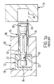
- the known joint forming device comprises an elongate fastening element 10 and a rotatable tightening element 12.
- the fastening element 10 is fixable to a first (14) of the joint members such that at least a head portion 16 thereof protrudes from the joint member.
- the tightening element 12 is rotatably mounted in a recess 18 in the second 20 of the joint members and has two arcuate camming surfaces 22 which are engageable with the head portion 16 of the fastening element.
- the joint forming device further comprises a sleeve 24 for the fastening element 10.
- One end of the sleeve 24 is fittable into a recess 26 in the first joint member 14.
- the fastening element 12 has a multi-tapered end portion 28 which is arranged to cause the sleeve to expand and forcibly engage a wall 30 of the recess 26 when the fastening element is moved axially relative to the sleeve.
- the sleeve 24 is fitted to the fastening element 10 and then inserted into a bore 32 in the second joint member 20.
- the bore 32 extends at right angles to and intersects the recess 18.
- the head portion 16 of the fastening element is received in a hollow central region of the tightening element so as to be engageable by the camming surfaces 22. This essentially is the position of the fastening element, sleeve and tightening element shown in Figure 1a.
- the end of the sleeve 24 which is not received in the bore 32 is inserted into the recess 26 in the first joint member 14.
- the tightening element is then rotated about its axis of rotation which axis is perpendicular to the longitudinal axis of the fastening element.
- the action of the camming surfaces 22 is to pull the fastening element axially away from the first joint member 14.
- the sleeve is prevented from moving with the fastening element by a sleeve collar 34 which abuts an end face 36 of the second joint member.
- the multi-tapered end portion 28 is drawn inwardly of the sleeve causing it to expand and forcibly engage the wall 30 of the recess 26. Further rotation of the tightening element causes the joint members to be pulled tightly together so that the joint members are in a state of compression and the fastening element is in a state of tension.
- FIG. 1b is a graph illustrating the relationship between rotation of the camming element and axial movement of the fastening element in a conventional joint forming device and showing the two-phase tightening action.
- Axial movement in mm is indicated along the vertical axis and rotation in degrees is indicated along the horizontal axis.
- a relatively "coarse movement" of the pin is provided by portions of the camming surfaces having a relatively steep, or tight, curve, i.e. a curvature adapted to provide a relatively large amount of axial movement of the fastening element for a relatively small amount of rotation of the camming element.
- the relationship between the rotation of the camming element and the axial movement caused is non-linear and is typically in excess of 0.5mm for each 10° of rotation.
- This "coarse movement” is provided for closing a gap between the two panels and causing them to be tightly pressed together, a movement often referred to as pull-up.
- the second phase of pin movement is caused by portions of the camming surfaces having a relatively flatter curve. The second-phase movement increases the compressive force on the joint and the reduced curvature of the camming surfaces imparts a degree of self-locking, often referred to as lock-up, to the joint forming device.
- camming elements designed to provide the above-mentioned two-phase pin movement are intended to be rotated sufficiently during tightening of the joint to ensure engagement between the head portion of the pin and the flatter portions of the camming surfaces to obtain so-called lock-up.
- the camming element which is the subject of Figure 1b, the camming element is rotated approximately 50 degrees from the position in which the head portion of the pin is inserted into the hollow region before the camming surfaces engage the head portion. The camming element must then be rotated a further 75 degrees before effective locking of the joint is obtained.
- a further problem associated with this design is that in order to cope with the relatively high forces acting on it, the camming element must be heavily built. If the camming element is not made strong, it may burst under the loads imposed on it; the phenomenon of cam bursting will be familiar to those skilled in the art.
- camming elements are produced in vast quantities usually by means of diecasting techniques. Diecasting metals are relatively expensive and it is therefore desirable to reduce the weight of metal required for each camming element as much as possible without significantly reducing the strength thereof.
- a further disadvantage of known joint forming devices is that they lack tolerance. That is, if the recesses and bores in which the device parts are fitted are not made accurately, it may not be possible to form a reliable joint.
- the camming element in use is usually fitted into a recess in a major surface of a first joint member.
- This recess either breaks an edge of the panel or is communicated with the edge by means of a bore which extends from the recess to the edge.
- This arrangement allows the head portion of the pin to be inserted into the camming element so that it can be engaged by the camming surfaces on rotation of the camming element.
- the camming element is located too far away from the edge of the joint member, unless an undue amount of force is applied, it is only possible to obtain a small amount of rotation of the camming element in the tightening direction. In this case it is not usually possible to rotate the camming element sufficiently for the head portion to engage the portion of the cam which provides lock-up and if rotation is continued, bursting of the cam can result. The result is that there is no effective locking action and the camming element will tend to back-off if the joint is loaded which results in a weak joint.
- US-A-5 567 081 provides a device for forming a joint between two members, said device comprising an elongate fastening element, a rotatable tightening element and a sleeve for said fastening element, said tightening element comprising at least one arcuate camming surface engageable with a head portion of said fastening element such that rotation of said tightening element about an axis of rotation thereof pulls said fastening element generally towards said axis of rotation, said sleeve being adapted such that, in use, a leading end thereof remains in a fixed position relative to said axis of rotation and said sleeve having an opposite end portion adapted to be radially expandable by said fastening element when so pulled for fixing said fastening element to one such joint member.
- the device according to the present invention is characterised in that the leading end of the sleeve is arranged to bear against a surface such as the outer peripheral surface of the tightening element in use of the device to hold said leading end in said fired position, and in that the sleeve has a collapsible zone adjacent its leading end which partially collapses in the lengthwise direction thereof under a compression force between the leading end of the sleeve and said opposite end upon rotation of the tightening element.
- the collapsible zone is provided in a wall of the sleeve.
- the device may comprise a plurality of collapsible zones at spaced apart locations along the length of the wall of the sleeve.
- the or each collapsible zone may comprise at least one portion of reduced thickness defined in said wall. Said portion or at least one of said portions of reduced thickness may define a groove extending in said lengthwise direction.
- the collapsible zone may comprise at least one aperture defined in said wall. Said aperture or at least one of said apertures may extend between said leading end and the opposite end portion of the sleeve. Said aperture or at least one of said apertures may be a cruciate aperture.
- the outer peripheral surface of the tightening element is disposed at a substantially constant radial distance from said axis of rotation of the tightening element.
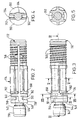
- a joint forming device comprises a tightening element in the form of a rotatable drum 110, a fastening element in the form of an elongate pin 112 and a sleeve 114 for the pin 112.
- the rotatable drum 110 which is shown in Figure 8 has an opening 116 through which a head portion 118 of the pin can be inserted into a hollow area at the centre of the drum.
- a slot 120 extends from the opening 116 partially circumferentially about the drum.
- the drum defines two arcuate camming surfaces 122, 124 which are separated one from the other by the slot 120.
- Suitable means are provided in the upper surface 126 of the drum to allow the drum to be rotated by means of a hand tool such as a screwdriver or hexagonal wrench.
- the pin 112 and drum 110 are so designed that the head portion 118 engages the camming surface 122 upon initial insertion in order to locate the pin in its correct position. This may occur in combination with the leading end 148 of the sleeve 114 engaging the outer peripheral surface 166 of the drum.
- the pin 12 which is preferably a diecast moulding, comprises the head portion 118, an expander portion disposed at the end of the pin opposite to the head portion and a shank 134 which extends between and interconnects the head and expander portions.
- the shank 134 is a plain cylinder whereas the expander portion comprises three frusto-conical portions 136, 138, 140 disposed in end-to-end relationship.
- the head portion 118 comprises a convex engaging surface 142 for cooperably engaging with the camming surfaces 122, 124 when the head portion 118 is received in the hollow interior of the rotatable drum 110.
- the head portion 118 is toroidal in shape.
- the engaging surface 142 may be provided with a plurality of circumferentially spaced apart protrusions 144 which are engageable with the camming surfaces 122, 124 or, more preferably, with depressions (not shown) provided in the camming surfaces. These protrusions and depressions, if provided, serve as a locking mechanism. For a more detailed description of the locking mechanism feature, attention is directed to the applicant's United Kingdom Patent No. 2246826.
- the sleeve 114 comprises a generally annular wall which defines a through-hole extending axially between the opposed ends of the sleeve.
- the through-hole is configured at one end to mate with the frusto-conical portions 136, 138, 140 of the pin 112.
- the remainder of the through-hole is configured to fit closely around the shank 134 of the pin.
- the leading end and expander portions of the pin 112 are somewhat larger in diameter than the portion of the through-hole which surrounds the shank 134.
- the sleeve will be made of a plastics material moulded directly onto the pin by a process known as insert moulding.
- the sleeve may comprise two parts which snap together about the pin in which case the parts of the sleeve may be hingeably connected.
- a helically extending barb 146 is provided on the outer surface of the sleeve for improving the grip between the sleeve and the joint member in which the barbed end is received.
- the barb 146 need not be helical and all manner of protrusions may be provided on the sleeve for the same purpose as is well known to those skilled in the art.
- the sleeve 114 is provided with collapsing means whereby the sleeve is partially collapsible in the lengthwise direction thereof.
- the collapsing means are adapted such that the strength of the sleeve in compression is selectively reduced.
- the collapsing means takes the form of two opposed apertures 150 each of which extends partially circumferentially of the sleeve and two cruciate apertures 152.
- the cruciate apertures 152 are disposed at opposite sides of the sleeve and have respective lengthwise extending portions which extend substantially over the entire length of the sleeve.
- the apertures 150 are disposed at the lefthand end (as viewed in Figures, 2, 3 and 6) of the sleeve and together with the lefthand ends of the lengthwise extending portions of the cruciate apertures 152 define four ribs 154 which connect a ring-like leading end portion 156 of the sleeve to the remainder of the sleeve.
- the transverse portions 158 of the cruciate slots 152 are arranged to define two opposed ribs 160 which are radially offset from the ribs 154 and in the radial direction extend generally perpendicular thereto.
- the apertures 150 and cruciate apertures 152 additionally define therebetween two arcuate segments 162.
- the ribs 160 connect the arcuate segments 162, the ribs 154 and the ring-like leading end portion 156 to the remainder of the sleeve. It will be appreciated that this arrangement of apertures, interconnecting ribs and arcuate segments defines a collapsible zone adjacent the leading end 156 of the sleeve.
- portions of the cruciate apertures 152 extending lengthwise of the sleeve from the transverse portions 160 to the barbed end of the sleeve also contribute, albeit to a lesser extent, to the collapsibility of the sleeve.
- the rotatable drum 110, pin 112 and sleeve 114 are fitted together in suitable recesses and bores provided in the joint members in the same general way as the fastening element 10, tightening element 12 and sleeve 24 of the known joint forming device shown in Figure 1a.
- the tightening procedure is likewise essentially the same. Accordingly, in the description which follows, use of the embodiment to form a joint between two members will be described with reference to the joint members shown in Figure 1a and like reference numerals will be used to specify the joint members together with their associated bores and recesses.
- the additional rotation of the drum made possible by the collapse of the sleeve provides two benefits. Firstly, if there is any gap between second joint member 14 and the end face 36 of the first joint member, as the pin is pulled inwardly of the drum, the gap is closed. Secondly, the collapse of the sleeve allows the two joint members when in abutting relationship to be tightly pulled together putting the joint members into compression in the region of the joint.
- collapsing means is not limited to the form shown in the embodiment.
- single apertures or groups of apertures may be provided at intervals along the sleeve to define a plurality of spaced apart collapsible zones.
- the collapsing means is not limited to apertures provided in the sleeve wall.
- recesses defining portions of reduced thickness may be provided in the sleeve wall thereby increasing the collapsibility of the sleeve.
- the position of the leading end portion 156 of the sleeve remains fixed relative to the axis of rotation of the drum 110. Because the sleeve remains fixed relative to the drum, the fastening element is able to move relative to the sleeve for expanding same. It will be understood that it is not essential for the leading end of the sleeve to engage the periphery of the drum in order for the position of the sleeve to be fixed relative to the axis of rotation of the drum.
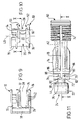
- a joint forming device for forming a joint between two members comprises a tightening element 10, a fastening element in the form of a pin 12 and a sleeve 14 for the pin.
- the tightening element 10 has a cylindrical drum-like body which comprises two generally cylindrical portions 15, 16 which are interconnected by means of a web 18.
- the drum-like body defines a centrally disposed cavity 20 for receiving a head portion 22 of the pin 12, a generally oblong opening 26 through which the head portion 22 can be inserted into the cavity 20 and a slot 28 which extends circumferentially about the body.
- the slot 28 is sized to receive a neck portion 30 of the pin 12 when, in use, the tightening element is rotated anticlockwise (as viewed in Figures 12 and 13) with the head portion 22 received in the cavity 20.
- a suitable aperture is provided in the uppermost surface (as viewed in Figures 9 and 10) of the body portion 15 to permit rotation of the tightening element by means of a suitable tool such as a screwdriver or the like.
- the drum-like body further defines two camming surfaces 32, 34 disposed one on each side of the slot 28.
- the camming surfaces 32, 34 are adapted for engaging an engaging surface 36 of the head portion 22.
- the camming surfaces In the lengthwise direction thereof, the camming surfaces have an arcuate profile which is configured such that when the tightening element is rotated anticlockwise whilst head portion 22 is engaged with the camming surfaces 32, 34, the pin 12 is caused to move in the axial direction thereof towards the axis of rotation 40 of the tightening element.
- the curvature of the arcuate profile of the camming surfaces is adapted to provide a substantially linear relationship between the amount of rotation of the tightening element and the amount of axial movement of the pin 12 over a substantial portion of the range of such movement as described in more detail hereinbelow and as shown in Figure 14.
- the camming surfaces 32, 34 are concave so as to provide extensive surface contact with a convex, preferably toroidal engaging surface 36 of the pin 12.
- a plurality of depressions 42 are provided in the camming surfaces 32, 34 at spaced apart locations along the length of the surfaces.
- the depressions 42 are configured to mate with conical protrusions 44 provided at substantially spaced apart locations on the engaging surface 36.
- the inter-engagement of the depressions 42 and protrusions 44 provides a ratchet-like locking mechanism which provides resistance to rotation of the tightening element in both the clockwise and anticlockwise directions.
- the web 18 has a generally U-shaped cross-section and is defined by relatively thin walls.
- the walls have a thickness in the range of 0.4 to 1.0mm. This configuration considerably reduces the weight of metal in the web and at the same time provides the necessary strength to maintain the body portions 15, 16 in a fixed spaced apart relationship.
- the cylindrical body portions 15, 16 are thinned in regions 50, 52 located to the rear of the tightening element diametrically opposite to the opening 26 such that the camming surfaces are defined on respective ribs 54, 56 which project from the body portions 15, 16.
- the web 18 defines the limit of the tightening element in the tightening direction as shown by Figure 13.
- the web is arranged such that the tightening element can be rotated about its axis of rotation 40 through an angle ⁇ of 225 degrees from the position in which the pin is inserted into the opening.
- the tightening element is formed by diecasting using a suitable zinc diecasting alloy.
- the pin 12 is preferably a diecast moulding and comprises the head portion 22, an expander portion 60 and a shank 62 which connects the head and expander portions.
- the shank 62 is a plain cylinder whereas the expander portion 60 comprises three frusto-conical portions 64, 66, 68 disposed in end-to-end relationship.
- the sleeve 14 for the pin 12 comprises a generally annular wall which defines a through-hole extending axially between the opposed ends of the sleeve.
- the through-hole is configured at one end to mate with the frusto-conical portions 64, 66, 68 of the pin 12.
- the remainder of the through-hole is configured to fit closely around the shank 62 of the pin.
- the head portion and expander portions of the pin 12 are somewhat larger in diameter than the portion of the through-hole which surrounds the shank 62.
- the sleeve will be made of a plastics material moulded directly onto the pin by a process known as insert moulding.
- the sleeve may comprise two parts which snap together about the pin in which case the parts of the sleeve may be hingeably connected.
- a helically extending barb 74 is provided on the outer surface of the sleeve for improving the grip between the sleeve and the joint member in which, in use, the barbed end is received.
- the barb 74 need not be helical and all manner of protrusions may be provided on the sleeve for the same purpose as is well known to those skilled in the art.
- the sleeve 14 is provided with collapsing means whereby the sleeve is partially collapsible in the lengthwise direction thereof.
- the collapsing means are adapted such that the strength of the sleeve in compression is selectively reduced.
- the collapsing means is defined by two opposed apertures 76 each of which extends partially circumferentially of the sleeve and two cruciate apertures 78.
- the cruciate apertures 78 are disposed at opposite sides of the sleeve and have respective lengthwise extending portions which extend substantially over the entire length of the sleeve.
- the apertures 76 are disposed at the lefthand end (as viewed in Figure 11) of the sleeve and together with the lefthand ends of the lengthwise extending portions of the cruciate apertures 78 define four ribs 80 which connect a ring-like leading end portion 82 of the sleeve to the remainder of the sleeve.
- the transverse portions 84 of the cruciate slots 78 are arranged to define two opposed ribs 86 which are radially offset from the ribs 80 and in the radial direction extend generally perpendicular thereto.
- the apertures 76 and cruciate apertures 78 additionally define therebetween two arcuate segments 88.
- the ribs 86 connect the arcuate segments 88, the ribs 80 and the ring-like leading end portion 82 to the remainder of the sleeve. It will be appreciated that this arrangement of apertures, interconnecting ribs and arcuate segments defines a collapsible zone adjacent the end 72 of the sleeve.
- portions of the cruciate apertures 78 extending lengthwise of the sleeve from the transverse portions 84 to the barbed end of the sleeve also contribute, albeit to a lesser extent, to the collapsibility of the sleeve.
- the tightening element 10, pin 12 and sleeve 14 are fitted together in suitable bores and recesses provided in the joint members.
- the tightening element is fitted into a recess formed in a major face of one edge of a first joint member and spaced a predetermined distance from an edge of the joint member.
- the recess housing the tightening element communicates with the edge of the first joint member by means of a bore extending perpendicular to the axis of the recess.
- the head portion 22 of the pin 12 can be inserted into the cavity 20 of the tightening element by aligning the oblong opening 26 with the bore in the first joint member and inserting the pin 12 and sleeve 14 into that bore.
- the tightening element 10 is rotated about its axis of rotation 40 to bring the camming surfaces 32, 34 into engagement with the engaging surface 36 of the pin 12.
- the neck 30 enters the slot 28 and the end face 72 of the sleeve 14 bears against the periphery of the tightening element on either side of the slot.
- the engagement between the sleeve 14 and the tightening element prevents axial movement of the sleeve relative to the tightening element so that as the tightening element causes the pin to move toward the axis of rotation 40, there is relative movement between the sleeve 14 and the pin 12.
- the additional rotation of the drum made possible by the collapse of the sleeve 14 provides two benefits. Firstly, if there is any gap between the joint members once the barbed end of the sleeve is expanded into its recess in the second joint member, the gap is closed. Secondly, the collapse of the sleeve allows the two joint members to be pulled together putting the joint members into compression in the region of the joint.
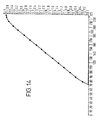
- Figure 14 shows the relationship between the amount of rotation of the tightening element 10 and the axial movement of the pin 12 caused by such rotation.
- the amount of rotation in mm is indicated along the vertical axis of the graph and the amount of rotation in degrees is indicated along the horizontal axis.
- the relationship between rotation and axial movement is substantially linear throughout the range of the axial movement of the pin. In the embodiment the relationship is that for each 10 degrees of rotation of the tightening element in the tightening direction, approximately 0.25mm of axial movement of the pin is caused.
- a further benefit of the relatively shallow curve of the arcuate camming surfaces is that lock-up can be achieved at substantially any point of engagement of the engaging surface and the camming surfaces.
- this lock-up is augmented by the locking mechanism provided by interengagement of the depressions 42 and protrusions 44 in order to provide a secure joint.
- the linear relationship between tightening element rotation and axial pin movement exists substantially throughout the range of pin movement.
- the linear relationship between tightening element rotation and axial pin movement exists substantially throughout the range of pin movement.
- at positions of maximum rotation it may be necessary to vary the curvature of the camming surfaces due to problems with coring in the moulding process.
- At the opposite end of the camming surfaces where engagement with the head portion 22 first occurs it may be necessary to provide a steeper curve to prevent the ribs which define the tightening surfaces becoming too thin at the periphery of the drum. It is, however, preferred that there is a linear relationship between camming element rotation and pin movement over at least 75 per cent of the range of said pin movement.
- the tightening elements must be rotated through an angle of 50 to 70 degrees before engagement of the camming surfaces and the head portion of the pin occurs.
- the extent of this pre-engagement rotation is determined by the dimensions of the opening through which the head portion is inserted into the tightening element central cavity and the position of the camming surfaces relative to the periphery of the tightening element.
- the tightening element 10 is able to provide linear camming action requiring low torque input with a range of axial movement of the pin comparable to that obtained using a conventional tightening element. This is particularly useful where the tightening element is used with a collapsible sleeve such as the sleeve of the embodiment. This allows the tightening element to be configured to provide sufficient axial movement of the pin to expand the barbed end of the sleeve and collapse the opposite end of the sleeve.
- the tightening element 10 and the joint forming device described herein will function to form a satisfactory joint even where there is a relatively wide degree of inaccuracy of the positioning of the recess for the tightening element relative to the edge of the joint member.
- the tightening element and the joint forming device can therefore be characterised as more tolerant than conventional tightening elements and joint forming devices.
Landscapes
- Engineering & Computer Science (AREA)
- General Engineering & Computer Science (AREA)
- Mechanical Engineering (AREA)
- Clamps And Clips (AREA)
- Coupling Device And Connection With Printed Circuit (AREA)
- Furniture Connections (AREA)
- Mechanical Coupling Of Light Guides (AREA)
- Molding Of Porous Articles (AREA)
- Seal Device For Vehicle (AREA)
- Surgical Instruments (AREA)
- Confectionery (AREA)
- Lining And Supports For Tunnels (AREA)
- Monitoring And Testing Of Exchanges (AREA)
- Manufacturing Of Electric Cables (AREA)
- Mutual Connection Of Rods And Tubes (AREA)
- Details Of Connecting Devices For Male And Female Coupling (AREA)
- Exchange Systems With Centralized Control (AREA)
Abstract
Description
Claims (26)
- A device for forming a joint between two members, said device comprising an elongate fastening element (112), a rotatable tightening element (110) and a sleeve (114) for said fastening element, said tightening element comprising at least one arcuate camming surface (122, 124) engageable with a head portion (118) of said fastening element such that rotation of said tightening element about an axis of rotation thereof pulls said fastening element generally towards said axis of rotation, said sleeve being adapted such that, in use, a leading end thereof remains in a fixed position relative to said axis of rotation and said sleeve having an opposite end portion adapted to be radially expandable by said fastening element when so pulled for fixing said fastening element to one such joint member, characterised in that the leading end (156) of the sleeve (114) is arranged to bear against a surface such as the outer peripheral surface of the tightening element (110) in use of the device to hold said leading end in said fixed position, and in that the sleeve has a collapsible zone (150, 152, 162) adjacent its leading end which partially collapses in the lengthwise direction thereof under a compression force between the leading end of the sleeve and said opposite end upon said rotation of the tightening element (110).
- A device as claimed in claim 1, wherein said collapsible zone (150, 152, 162) is provided in a wall of the sleeve.
- A device as claimed in claim 2, and comprising a plurality of collapsible zones (150, 152, 162) at spaced apart locations along the length of the wall of the sleeve (114).
- A device as claimed in claim 2 or 3, wherein the or each collapsible zone (150, 152, 162) comprises at least one portion of reduced thickness defined in said wall.
- A device as claimed in claim 4, wherein said portion or at least one of said portions of reduced thickness defines a groove extending in said lengthwise direction.
- A device as claimed in any one of claims 2 to 5, wherein said collapsible zone (150, 152, 162) comprises at least one aperture defined in said wall.
- A device as claimed in claim 5, wherein said aperture or at least one of said apertures extends between said leading end and the opposite end portion of the sleeve (114).
- A device as claimed in claim 6 or 7, wherein said aperture or at least one of said apertures is a cruciate aperture.
- A device as claimed in any preceding claim wherein the leading end of the sleeve (114) remains in said fixed position by virtue of its engagement with the outer peripheral surface of the tightening element (110).
- A device as claimed in claim 9, wherein said outer peripheral surface of the tightening element (110) is disposed at a substantially constant radial distance from said axis of rotation thereof.
- A device as claimed in any one of the preceding claims wherein the tightening element (110) comprises a body which has an axis of rotation and defines a generally centrally disposed cavity for receiving said head portion (118) of the fastening element (112), an opening through which said head portion can be inserted into said cavity and a slot extending from said opening about said body for receiving a neck portion of the fastening element when, in use, the tightening element is rotated in one direction about said axis of rotation with said head portion received in the cavity, the slot being adapted to permit rotation of the tightening element in said one direction through an angle of at least 190 degrees.
- A device as claimed in claim 11, wherein said slot is adapted to permit said rotation in said one direction through a maximum angle in the range 190 to 225 degrees.
- A device as claimed in claim 11 or 12, wherein the profile of the or each said camming surface (122, 124) is such that the relation between the amount of said axial movement of the fastening element (112) and the amount of rotation of the tightening element (110) in said one direction is substantially constant over at least 75 per cent of the range of said axial movement.
- A device as claimed in claim 13, wherein said camming surface profile is adapted to cause less than 0.3mm said axial movement for each 10 degrees of rotation of the tightening element (110) in said one direction.
- A device as claimed in claim 14, wherein said camming surface profile is adapted to cause approximately 0.25mm said axial movement for each 10 degrees of rotation of the tightening element (110) in said one direction.
- A device as claimed in claim 13, 14 or 15, wherein the relation between the amount of said axial movement of the fastening element (112) and the amount of rotation of the tightening element (110) in said one direction is substantially constant substantially throughout the range of said axial movement.
- A device as claimed in any one of the preceding claims, wherein in directions transverse the arcuate length thereof, the or each camming surface (122, 124) is concave.
- A device as claimed in any one of claims 11 to 17, wherein said body is generally cylindrical.
- A device as claimed in claim 18, wherein said body comprises a first cylindrical portion and a second cylindrical portion interconnected by web means.
- A device as claimed in claim 19, wherein said web means comprises a generally U-shaped section.
- A device as claimed in claim 19 or 20, wherein said web means defines the limit of said rotation in said one direction.
- A device as claimed in claim 19, 20 or 21, wherein the or at least one said camming surface (122, 124) is defined by a rib projecting from one of said cylindrical portions.
- A device as claimed in any one of claims 11 to 22, wherein said body has a diameter of approximately 15mm or less.
- A device as claimed in any one of the preceding claims, wherein said tightening element (110) comprises formations adapted to cooperate with said head portion (118) of the fastening element (112) for facilitating interlocking engagement therewith.
- A device as claimed in claim 24, wherein said formations comprise a plurality of depressions disposed in said tightening element (110).
- A device as claimed in any one of claims 17 to 25, wherein said head portion (118) of the fastening element (112) defines a convex engaging surface for engaging the or each said camming surface (122, 124).
Applications Claiming Priority (5)
| Application Number | Priority Date | Filing Date | Title |
|---|---|---|---|
| GBGB9704985.2A GB9704985D0 (en) | 1997-03-11 | 1997-03-11 | Joint forming devices |
| GB9704985 | 1997-03-11 | ||
| GBGB9708955.1A GB9708955D0 (en) | 1997-03-11 | 1997-05-01 | Camming element for joint forming devices |
| GB9708955 | 1997-05-01 | ||
| PCT/GB1998/000723 WO1998040634A1 (en) | 1997-03-11 | 1998-03-05 | Joint forming device |
Publications (2)
| Publication Number | Publication Date |
|---|---|
| EP0970311A1 EP0970311A1 (en) | 2000-01-12 |
| EP0970311B1 true EP0970311B1 (en) | 2003-09-17 |
Family
ID=26311159
Family Applications (1)
| Application Number | Title | Priority Date | Filing Date |
|---|---|---|---|
| EP98910861A Expired - Lifetime EP0970311B1 (en) | 1997-03-11 | 1998-03-05 | Joint forming device |
Country Status (11)
| Country | Link |
|---|---|
| US (1) | US6276868B1 (en) |
| EP (1) | EP0970311B1 (en) |
| JP (1) | JP4339932B2 (en) |
| CN (1) | CN1123702C (en) |
| AT (1) | ATE250187T1 (en) |
| AU (1) | AU6508798A (en) |
| BR (1) | BR9806695A (en) |
| DE (2) | DE19881663C2 (en) |
| DK (1) | DK0970311T3 (en) |
| ES (1) | ES2206902T3 (en) |
| WO (1) | WO1998040634A1 (en) |
Families Citing this family (24)
| Publication number | Priority date | Publication date | Assignee | Title |
|---|---|---|---|---|
| US6886286B2 (en) * | 2001-08-10 | 2005-05-03 | Samuel F. Dowding | Method of attaching the stock of a firearm to a frame |
| WO2003027510A2 (en) * | 2001-09-26 | 2003-04-03 | Agostino Ferrari S.P.A. | Device and method for detachably connecting abutting structural parts and tie member for use to form said device |
| DE20118279U1 (en) | 2001-11-09 | 2002-01-31 | Häfele GmbH & Co., 72202 Nagold | Link between two components |
| DE20120256U1 (en) * | 2001-12-14 | 2002-03-07 | Häfele GmbH & Co., 72202 Nagold | fitting |
| GB2383392B (en) * | 2001-12-18 | 2004-09-15 | Titus Int Plc | Improvements in fastening devices |
| US6946715B2 (en) * | 2003-02-19 | 2005-09-20 | Micron Technology, Inc. | CMOS image sensor and method of fabrication |
| CN100491750C (en) * | 2004-03-03 | 2009-05-27 | 快连有限公司 | Improvements to clamping components |
| GB2430991B (en) * | 2005-10-07 | 2008-09-10 | Titus Int Plc | Improvements in joint forming devices |
| US20070113495A1 (en) * | 2005-11-23 | 2007-05-24 | Roberts John F | Modular assembly system |
| US20070113484A1 (en) * | 2005-11-23 | 2007-05-24 | Mcgregor Jean T | Modular assembly system |
| DE102006024265B3 (en) * | 2006-05-24 | 2008-01-10 | Festool Gmbh | Fitting device for connecting two furniture parts |
| US20080075528A1 (en) * | 2006-09-22 | 2008-03-27 | Michael Marzetta | Construction system |
| GB2443425B (en) * | 2006-11-01 | 2010-11-03 | Titus Int Plc | Improvements in fasteners |
| GB2443424B (en) * | 2006-11-01 | 2010-10-27 | Titus Int Plc | Improvements in fasteners |
| US7824141B2 (en) * | 2007-08-03 | 2010-11-02 | Newfrey Llc | Blind rivet |
| CN201162746Y (en) * | 2007-09-21 | 2008-12-10 | 深圳何群家具有限公司 | Eccentric combiner (1) |
| JP5650547B2 (en) * | 2008-03-14 | 2015-01-07 | ラム リサーチ コーポレーションLam Research Corporation | Cam lock electrode clamp |
| USD725796S1 (en) | 2013-05-23 | 2015-03-31 | Endura Products, Inc. | Door jamb extension assembly |
| CN107407310B (en) * | 2014-12-12 | 2020-09-11 | 拉玛德卡尼股份公司 | Improvement of connection forming equipment |
| ITUA20162145A1 (en) * | 2016-03-31 | 2017-10-01 | Effegi Brevetti Srl | JUNCTION DEVICE PERFORMED FOR FURNITURE PARTS AND FURNISHINGS |
| US10722029B2 (en) | 2017-04-20 | 2020-07-28 | David O. Boone Revocable Trust | Framed full access cabinet |
| GB2564080A (en) * | 2017-04-25 | 2019-01-09 | Titus D O O Dekani | Improvements in joint forming devices |
| DE202019101077U1 (en) * | 2019-02-25 | 2019-04-02 | Häfele Berlin Gmbh & Co Kg | spreading connectors |
| USD1074417S1 (en) * | 2023-09-25 | 2025-05-13 | Yangjiang Yugongfang Home Furnishings Co., Ltd | Furniture connector |
Family Cites Families (10)
| Publication number | Priority date | Publication date | Assignee | Title |
|---|---|---|---|---|
| DE2625182C3 (en) * | 1976-03-11 | 1980-06-19 | Richard Heinze Gmbh & Co Kg, 4900 Herford | Fitting for the detachable connection of two components, in particular panel-shaped components for furniture |
| GB2246826B (en) * | 1990-08-07 | 1993-08-04 | Titus Int Ltd | Fastening devices |
| DE9216182U1 (en) * | 1992-11-27 | 1993-01-21 | Häfele GmbH & Co., 7270 Nagold | fitting |
| GB2305226B (en) * | 1993-12-23 | 1997-07-16 | Titus Int Plc | Joint forming device |
| ATE168172T1 (en) * | 1994-11-04 | 1998-07-15 | Lautenschlaeger Mepla Werke | CONNECTION FITTING |
| GB2301644B (en) * | 1995-05-31 | 1999-03-10 | Titus Int Plc | Joint forming devices |
| GB2301412B (en) * | 1995-05-31 | 1999-03-10 | Titus Int Plc | A housing for joint forming devices |
| GB2301413B (en) * | 1995-05-31 | 1999-03-10 | Titus Int Plc | Joint forming devices |
| GB2301643B (en) * | 1995-05-31 | 1999-06-23 | Titus Int Plc | Joint forming devices |
| US5823700A (en) * | 1996-09-18 | 1998-10-20 | Bush Industries, Inc. | Drawer front fastener |
-
1998
- 1998-03-05 US US09/308,138 patent/US6276868B1/en not_active Expired - Lifetime
- 1998-03-05 CN CN98801383.5A patent/CN1123702C/en not_active Expired - Fee Related
- 1998-03-05 JP JP53935598A patent/JP4339932B2/en not_active Expired - Fee Related
- 1998-03-05 AT AT98910861T patent/ATE250187T1/en not_active IP Right Cessation
- 1998-03-05 ES ES98910861T patent/ES2206902T3/en not_active Expired - Lifetime
- 1998-03-05 WO PCT/GB1998/000723 patent/WO1998040634A1/en not_active Ceased
- 1998-03-05 DK DK98910861T patent/DK0970311T3/en active
- 1998-03-05 EP EP98910861A patent/EP0970311B1/en not_active Expired - Lifetime
- 1998-03-05 BR BR9806695-1A patent/BR9806695A/en not_active IP Right Cessation
- 1998-03-05 DE DE19881663T patent/DE19881663C2/en not_active Expired - Fee Related
- 1998-03-05 DE DE69818237T patent/DE69818237D1/en not_active Expired - Lifetime
- 1998-03-05 AU AU65087/98A patent/AU6508798A/en not_active Abandoned
Also Published As
| Publication number | Publication date |
|---|---|
| AU6508798A (en) | 1998-09-29 |
| ES2206902T3 (en) | 2004-05-16 |
| JP2001524185A (en) | 2001-11-27 |
| JP4339932B2 (en) | 2009-10-07 |
| DK0970311T3 (en) | 2004-01-26 |
| ATE250187T1 (en) | 2003-10-15 |
| DE19881663T1 (en) | 1999-11-18 |
| DE69818237D1 (en) | 2003-10-23 |
| WO1998040634A1 (en) | 1998-09-17 |
| CN1254400A (en) | 2000-05-24 |
| BR9806695A (en) | 2000-02-29 |
| CN1123702C (en) | 2003-10-08 |
| EP0970311A1 (en) | 2000-01-12 |
| US6276868B1 (en) | 2001-08-21 |
| DE19881663C2 (en) | 2003-04-10 |
Similar Documents
| Publication | Publication Date | Title |
|---|---|---|
| US6276868B1 (en) | Joint forming device | |
| EP0736143B1 (en) | Joint forming device | |
| CN1322243C (en) | Device and method for detachably connecting abutting structural parts and tie member for use to form said device | |
| CA1250159A (en) | Expansion dowel assembly | |
| EP0611002B1 (en) | Quick removable fasteners in particular for furniture | |
| US6547477B1 (en) | Connecting fitting | |
| US20030223840A1 (en) | Panel fastener | |
| EP1015775B1 (en) | Joint forming devices | |
| CA1237005A (en) | Expansion dowel assembly | |
| EP0560518B1 (en) | Universal plug | |
| US20220265075A1 (en) | Adjustable Rod Features | |
| US20020076298A1 (en) | Anchor with an expansible sleeve for hard material | |
| US20050002750A1 (en) | Fastening devices | |
| US6142700A (en) | Joint forming devices | |
| US5401131A (en) | Expansion anchor | |
| US4566832A (en) | Sleeve-shaped expansion dowel | |
| US4080081A (en) | Method of joining a rattan pole to a member | |
| US5836713A (en) | Coupling mechanism for establishing an involute spline connection | |
| GB2598400A (en) | Assembly | |
| US20040013491A1 (en) | Anchor and nut assembly | |
| GB2129899A (en) | Expansible anchor | |
| JPH10110475A (en) | Anchor metal fixture | |
| CA1153916A (en) | Hollow wall fastener | |
| JPH0656172B2 (en) | Driving anchor | |
| GB2215420A (en) | Wall anchors |
Legal Events
| Date | Code | Title | Description |
|---|---|---|---|
| PUAI | Public reference made under article 153(3) epc to a published international application that has entered the european phase |
Free format text: ORIGINAL CODE: 0009012 |
|
| 17P | Request for examination filed |
Effective date: 19990702 |
|
| AK | Designated contracting states |
Kind code of ref document: A1 Designated state(s): AT BE CH DE DK ES FI FR GB GR IE IT LI LU MC NL PT SE |
|
| 17Q | First examination report despatched |
Effective date: 20000516 |
|
| GRAH | Despatch of communication of intention to grant a patent |
Free format text: ORIGINAL CODE: EPIDOS IGRA |
|
| GRAS | Grant fee paid |
Free format text: ORIGINAL CODE: EPIDOSNIGR3 |
|
| GRAA | (expected) grant |
Free format text: ORIGINAL CODE: 0009210 |
|
| AK | Designated contracting states |
Kind code of ref document: B1 Designated state(s): AT BE CH DE DK ES FI FR GB GR IE IT LI LU MC NL PT SE |
|
| PG25 | Lapsed in a contracting state [announced via postgrant information from national office to epo] |
Ref country code: NL Free format text: LAPSE BECAUSE OF FAILURE TO SUBMIT A TRANSLATION OF THE DESCRIPTION OR TO PAY THE FEE WITHIN THE PRESCRIBED TIME-LIMIT Effective date: 20030917 Ref country code: LI Free format text: LAPSE BECAUSE OF FAILURE TO SUBMIT A TRANSLATION OF THE DESCRIPTION OR TO PAY THE FEE WITHIN THE PRESCRIBED TIME-LIMIT Effective date: 20030917 Ref country code: FI Free format text: LAPSE BECAUSE OF FAILURE TO SUBMIT A TRANSLATION OF THE DESCRIPTION OR TO PAY THE FEE WITHIN THE PRESCRIBED TIME-LIMIT Effective date: 20030917 Ref country code: CH Free format text: LAPSE BECAUSE OF FAILURE TO SUBMIT A TRANSLATION OF THE DESCRIPTION OR TO PAY THE FEE WITHIN THE PRESCRIBED TIME-LIMIT Effective date: 20030917 Ref country code: BE Free format text: LAPSE BECAUSE OF FAILURE TO SUBMIT A TRANSLATION OF THE DESCRIPTION OR TO PAY THE FEE WITHIN THE PRESCRIBED TIME-LIMIT Effective date: 20030917 Ref country code: AT Free format text: LAPSE BECAUSE OF FAILURE TO SUBMIT A TRANSLATION OF THE DESCRIPTION OR TO PAY THE FEE WITHIN THE PRESCRIBED TIME-LIMIT Effective date: 20030917 |
|
| REG | Reference to a national code |
Ref country code: GB Ref legal event code: FG4D |
|
| REG | Reference to a national code |
Ref country code: CH Ref legal event code: EP |
|
| REF | Corresponds to: |
Ref document number: 69818237 Country of ref document: DE Date of ref document: 20031023 Kind code of ref document: P |
|
| REG | Reference to a national code |
Ref country code: IE Ref legal event code: FG4D |
|
| RBV | Designated contracting states (corrected) |
Designated state(s): AT BE CH DK ES FI FR GR IE IT LI LU MC NL PT SE |
|
| PG25 | Lapsed in a contracting state [announced via postgrant information from national office to epo] |
Ref country code: SE Free format text: LAPSE BECAUSE OF FAILURE TO SUBMIT A TRANSLATION OF THE DESCRIPTION OR TO PAY THE FEE WITHIN THE PRESCRIBED TIME-LIMIT Effective date: 20031217 Ref country code: GR Free format text: LAPSE BECAUSE OF FAILURE TO SUBMIT A TRANSLATION OF THE DESCRIPTION OR TO PAY THE FEE WITHIN THE PRESCRIBED TIME-LIMIT Effective date: 20031217 |
|
| PG25 | Lapsed in a contracting state [announced via postgrant information from national office to epo] |
Ref country code: PT Free format text: LAPSE BECAUSE OF FAILURE TO SUBMIT A TRANSLATION OF THE DESCRIPTION OR TO PAY THE FEE WITHIN THE PRESCRIBED TIME-LIMIT Effective date: 20031226 |
|
| REG | Reference to a national code |
Ref country code: DK Ref legal event code: T3 |
|
| NLV1 | Nl: lapsed or annulled due to failure to fulfill the requirements of art. 29p and 29m of the patents act | ||
| PG25 | Lapsed in a contracting state [announced via postgrant information from national office to epo] |
Ref country code: LU Free format text: LAPSE BECAUSE OF NON-PAYMENT OF DUE FEES Effective date: 20040305 Ref country code: IE Free format text: LAPSE BECAUSE OF NON-PAYMENT OF DUE FEES Effective date: 20040305 |
|
| PG25 | Lapsed in a contracting state [announced via postgrant information from national office to epo] |
Ref country code: MC Free format text: LAPSE BECAUSE OF NON-PAYMENT OF DUE FEES Effective date: 20040331 |
|
| REG | Reference to a national code |
Ref country code: CH Ref legal event code: PL |
|
| REG | Reference to a national code |
Ref country code: ES Ref legal event code: FG2A Ref document number: 2206902 Country of ref document: ES Kind code of ref document: T3 |
|
| ET | Fr: translation filed | ||
| PLBE | No opposition filed within time limit |
Free format text: ORIGINAL CODE: 0009261 |
|
| STAA | Information on the status of an ep patent application or granted ep patent |
Free format text: STATUS: NO OPPOSITION FILED WITHIN TIME LIMIT |
|
| 26N | No opposition filed |
Effective date: 20040618 |
|
| REG | Reference to a national code |
Ref country code: IE Ref legal event code: MM4A |
|
| PG25 | Lapsed in a contracting state [announced via postgrant information from national office to epo] |
Ref country code: IT Free format text: LAPSE BECAUSE OF NON-PAYMENT OF DUE FEES Effective date: 20050305 |
|
| PGFP | Annual fee paid to national office [announced via postgrant information from national office to epo] |
Ref country code: DK Payment date: 20090313 Year of fee payment: 12 |
|
| PGFP | Annual fee paid to national office [announced via postgrant information from national office to epo] |
Ref country code: FR Payment date: 20090316 Year of fee payment: 12 |
|
| PGRI | Patent reinstated in contracting state [announced from national office to epo] |
Ref country code: IT Effective date: 20091201 |
|
| REG | Reference to a national code |
Ref country code: DK Ref legal event code: EBP |
|
| REG | Reference to a national code |
Ref country code: FR Ref legal event code: ST Effective date: 20101130 |
|
| PG25 | Lapsed in a contracting state [announced via postgrant information from national office to epo] |
Ref country code: FR Free format text: LAPSE BECAUSE OF NON-PAYMENT OF DUE FEES Effective date: 20100331 |
|
| PG25 | Lapsed in a contracting state [announced via postgrant information from national office to epo] |
Ref country code: DK Free format text: LAPSE BECAUSE OF NON-PAYMENT OF DUE FEES Effective date: 20100331 |
|
| PGFP | Annual fee paid to national office [announced via postgrant information from national office to epo] |
Ref country code: ES Payment date: 20120731 Year of fee payment: 15 Ref country code: IT Payment date: 20120814 Year of fee payment: 15 |
|
| PG25 | Lapsed in a contracting state [announced via postgrant information from national office to epo] |
Ref country code: IT Free format text: LAPSE BECAUSE OF NON-PAYMENT OF DUE FEES Effective date: 20130305 |
|
| REG | Reference to a national code |
Ref country code: DE Ref legal event code: R107 Ref document number: 69818237 Country of ref document: DE Effective date: 20140424 |
|
| REG | Reference to a national code |
Ref country code: ES Ref legal event code: FD2A Effective date: 20140606 |
|
| PG25 | Lapsed in a contracting state [announced via postgrant information from national office to epo] |
Ref country code: ES Free format text: LAPSE BECAUSE OF NON-PAYMENT OF DUE FEES Effective date: 20130306 |