EP0969641B1 - Téléphone mobile avec écran tactile et clavier - Google Patents
Téléphone mobile avec écran tactile et clavier Download PDFInfo
- Publication number
- EP0969641B1 EP0969641B1 EP19990401255 EP99401255A EP0969641B1 EP 0969641 B1 EP0969641 B1 EP 0969641B1 EP 19990401255 EP19990401255 EP 19990401255 EP 99401255 A EP99401255 A EP 99401255A EP 0969641 B1 EP0969641 B1 EP 0969641B1
- Authority
- EP
- European Patent Office
- Prior art keywords
- screen
- telephone according
- panel
- mobile telephone
- action
- Prior art date
- Legal status (The legal status is an assumption and is not a legal conclusion. Google has not performed a legal analysis and makes no representation as to the accuracy of the status listed.)
- Expired - Lifetime
Links
- 230000006870 function Effects 0.000 claims description 13
- 230000003287 optical effect Effects 0.000 claims description 7
- 230000005540 biological transmission Effects 0.000 claims description 4
- 229920001971 elastomer Polymers 0.000 claims description 2
- 239000000806 elastomer Substances 0.000 claims description 2
- 239000004417 polycarbonate Substances 0.000 claims description 2
- 229920000515 polycarbonate Polymers 0.000 claims description 2
- 230000004048 modification Effects 0.000 claims 1
- 238000012986 modification Methods 0.000 claims 1
- 230000035807 sensation Effects 0.000 claims 1
- 239000008188 pellet Substances 0.000 description 7
- 238000001514 detection method Methods 0.000 description 5
- 238000005516 engineering process Methods 0.000 description 5
- 230000000875 corresponding effect Effects 0.000 description 3
- 239000012528 membrane Substances 0.000 description 3
- 239000002184 metal Substances 0.000 description 3
- 230000000873 masking effect Effects 0.000 description 2
- 230000015654 memory Effects 0.000 description 2
- 230000008447 perception Effects 0.000 description 2
- 238000010521 absorption reaction Methods 0.000 description 1
- 229910021417 amorphous silicon Inorganic materials 0.000 description 1
- 238000013459 approach Methods 0.000 description 1
- 239000011248 coating agent Substances 0.000 description 1
- 238000000576 coating method Methods 0.000 description 1
- 238000004891 communication Methods 0.000 description 1
- 230000006835 compression Effects 0.000 description 1
- 238000007906 compression Methods 0.000 description 1
- 238000012790 confirmation Methods 0.000 description 1
- 230000007423 decrease Effects 0.000 description 1
- 230000001419 dependent effect Effects 0.000 description 1
- 230000006866 deterioration Effects 0.000 description 1
- 238000011161 development Methods 0.000 description 1
- 239000011521 glass Substances 0.000 description 1
- 239000011159 matrix material Substances 0.000 description 1
- 238000005259 measurement Methods 0.000 description 1
- 235000010603 pastilles Nutrition 0.000 description 1
- 229920001296 polysiloxane Polymers 0.000 description 1
- 125000006850 spacer group Chemical group 0.000 description 1
- 230000003936 working memory Effects 0.000 description 1
Images
Classifications
-
- H—ELECTRICITY
- H04—ELECTRIC COMMUNICATION TECHNIQUE
- H04M—TELEPHONIC COMMUNICATION
- H04M1/00—Substation equipment, e.g. for use by subscribers
- H04M1/02—Constructional features of telephone sets
- H04M1/0202—Portable telephone sets, e.g. cordless phones, mobile phones or bar type handsets
- H04M1/0206—Portable telephones comprising a plurality of mechanically joined movable body parts, e.g. hinged housings
- H04M1/0208—Portable telephones comprising a plurality of mechanically joined movable body parts, e.g. hinged housings characterized by the relative motions of the body parts
- H04M1/0214—Foldable telephones, i.e. with body parts pivoting to an open position around an axis parallel to the plane they define in closed position
-
- H—ELECTRICITY
- H04—ELECTRIC COMMUNICATION TECHNIQUE
- H04M—TELEPHONIC COMMUNICATION
- H04M1/00—Substation equipment, e.g. for use by subscribers
- H04M1/02—Constructional features of telephone sets
- H04M1/0202—Portable telephone sets, e.g. cordless phones, mobile phones or bar type handsets
- H04M1/0206—Portable telephones comprising a plurality of mechanically joined movable body parts, e.g. hinged housings
- H04M1/0241—Portable telephones comprising a plurality of mechanically joined movable body parts, e.g. hinged housings using relative motion of the body parts to change the operational status of the telephone set, e.g. switching on/off, answering incoming call
- H04M1/0245—Portable telephones comprising a plurality of mechanically joined movable body parts, e.g. hinged housings using relative motion of the body parts to change the operational status of the telephone set, e.g. switching on/off, answering incoming call using open/close detection
-
- H—ELECTRICITY
- H04—ELECTRIC COMMUNICATION TECHNIQUE
- H04M—TELEPHONIC COMMUNICATION
- H04M2250/00—Details of telephonic subscriber devices
- H04M2250/22—Details of telephonic subscriber devices including a touch pad, a touch sensor or a touch detector
Definitions
- the present invention relates to a mobile phone with a touch screen and a mechanical keyboard. It aims to simplify the realization of this mobile phone while retaining the interest of both technologies.
- optical detection screens including infrared, comprise a matrix of optical switches comprising a light emitting diode in connection with a phototransistor. A stylus comes to cut, at a point of contact with the screen, the light beam. The absence of light is detected by the phototransistor. A detection signal in relation to the coordinates of the phototransistor designates an area of the screen.
- Acoustic detection screens have a generation of one acoustic wave. When a stylus comes into contact with the screen, it changes the acoustic impedance here. It absorbs some of the energy of this wave. This absorption is detected by an electronic control device which designates in correspondence a zone of the screen.
- Capacitive-sensing screens have a dielectric slab, made of glass, covered with a thin metal coating through which a weak current flows. The contact of a conductive stylus causes a slight increase in the current. The coordinates of the contact are measured from the measurement of this current at the four corners of this device.
- Resistive sensing screens have two transparent membranes covered with a thin metal film and separated by insulating spacers. Both membranes are energized in turn by a constant DC voltage. At the points of contact, a connection is established between the two membranes. Its detection makes it possible to determine the coordinates of the contact zone.
- the existing mobile phone solutions consist either of placing the keys on the keyboard on the back of the devices or to provide them with a shutter and to install the keys on the shutter.
- the shutter slips or folds normally on the screen to protect it and to reduce the size of the mobile phone.
- the keys can be selected either closed or open. In which case, the keys appear respectively outside or inside the pane, the parts of this pane which are visible to the user when this pane is respectively closed or open.
- the shutter is closed, it may mask all or only part of the screen, so that some of the indications mentioned by it remains legible for the user.
- the closed shutter solution preferably with partial masking of the screen, is particularly useful and well suited to use.
- the realization of a mobile phone arranged in this way presents difficulties. Indeed, the keypad installed in the shutter can be connected to the mobile phone only by a sheet of son who pass in the folding hinge of the shutter safe mobile phone.
- the object of the invention is to provide a solution to this problem of reliability in a definitive manner.
- the principle of the invention is simply to remove the web of electrical connections since it is she who is the seat of failures.
- the screen is a touch screen and is used as the sole functional control unit of the mobile phone.
- the shutter of the mobile phone of the invention is then provided with passages, including flexible passages, to transmit through it actions, pressure forces or presentations, to sensitive areas of the touch screen located opposite.
- a telephone according to the invention also comprises an opening / closing position detector of the shutter.
- Such detectors are known from WO 98/15094 and GB 2297662. These detectors however require mechanical arrangements, which reduces the reliability of the telephone.
- the subject of the invention is therefore a mobile telephone provided with a screen, a shutter and a computer system controlled by a program, comprising a detector for opening or closing the shutter, functions of the telephone being dependent on the open or closed state of the shutter, characterized in that the shutter opening and closing detector is an optical detector mounted in the screen.
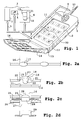
- Figure 1 shows a mobile phone 1 with a screen 2.
- the screen 2 is a touch screen.
- the screen 2 occupies almost the entire front of the mobile phone 1, the one that is in contact with the user when he talks with the mobile phone.
- the mobile telephone 1 furthermore comprises a computer system 3 equipped with a microprocessor 4 connected by a bus 5 to a program memory 6, a working memory 7, a microphone 8, a loudspeaker 9 and receiving transmission means 10.
- the touch screen 2 allows pressing keys such as 11 to 12 to select functions of the mobile phone and in particular to enter into communication with a distant party and exchange words with him.
- a program 13 contained in the memory 6 manages both the devices 6 to 12 of the mobile phone and the various possible uses.
- the mobile phone of the invention also comprises a flap 14.
- the flap 14 can be operated by sliding, or by rotation around a hinge 15, to mask the screen 2. Especially if the screen is touch, the flap 14 is intended to protect the screen 2.
- the invention applies to both the sliding shutters and flaps folded. Preferably when masking the screen only a lower portion of the screen is hidden.
- the flap 14 when the flap 14 hides the screen 2, it has passages 16 to allow the transmission of an action, for example a pressure force, on sensitive areas of the touch screen.
- an action for example a pressure force
- the flap 14 may have holes 16 facing each one of one or more of the sensitive areas 11 to 12 of the screen 2.
- transmission passages that facing part of the screen areas 2.
- each hole 16 may be provided with a silicone pellet.
- a pellet 17, seen in section has an elliptical shape for protruding on the outer face of the flap 14 (so that the user recognizes the relief), and under an internal face of the flap 14 (in order to approach as much as possible to zones 11-12 and reduce the distance needed during a support).
- Plan view the pastilles can have all the desired shapes given a sought aesthetic presentation: be square, rectangular, round, oval and so on.
- the pellets 17 for closing the holes will nevertheless have rather the shape 18 represented on the FIG. 2.
- the shape 18 of these pellets then consists of a cup 19 which bears on both sides 20 and 21 on the edges of the holes 16 and a boss 22 located inside the cup, substantially in the middle.
- the shape of the cup 19 naturally tends to pull the hump 22 in a direction 23 away from the underlying touch screen 2.
- In the closed position of the shutter there is a gap, for example 1/10 th of millimeters, between the boss 22 and the screen 2.
- the boss 22 presses on an area 11 of the screen 2.
- the circuits 4 to 12 of the mobile phone then detect this pressure or presence near the hump 22 and cause a corresponding action.
- FIG. 2c shows a preferred embodiment of the flexible shutters placed in the passages 16.
- These comprise, in stacking, vertically above the passages 16, a key 23 superimposed on a boss 24, made in a flexible sheet 25 , and a semi-rigid sheet 26 provided with holes 27.
- the key 23 has a cup shape.
- the cup 23 may be hollow and have a hole 28. It is itself flexible as the cup 19 of the pellet 18. This cup 23 is pressed on the boss 24.
- the boss 24 will then pass through the hole 27 of the sheet 26 to come to press or appear on an area of the touch screen (not shown).
- the surface of the hump 24 is flush with the sheet 26 and the top of the cup 23 protrudes from the outer face of the flap 14.
- the movable key 23 is made of metal, the bump 24 and the sheet flexible 25 are elastomer, the semi-rigid sheet 26 is polycarbonate.
- the sheet 26 is glued from place to place, or on its edges, to the flap 14 to hold all of these parts. If necessary the cups 23 are also carried by a sheet placed in an intermediate position in the stack.
- the key 23 may be replaced by a button 29 whose upper portion is intended to pass through the holes 16.
- the flexibility of the closure is only caused by the flexibility of the boss 24.
- the solution with the cup 18 or the cup 23 may be preferred because it causes a particular feeling to the sink. Indeed with such a cup, the driving force is applied to a portion of the driving stroke before, because of the overturning of the cup, the resistance of the latter decreases substantially. This variation of resistance is perceived by the user as a confirmation of the realization of the support.
- this perception either does not exist or must be created by other means.
- FIGS. 2b and 2c particularly in the case of FIG. 2c, it is possible to obtain the emission of a natural noise (plop) only with the compression tilting of the cup.
- these devices are further improved by disposing in the mobile phone an opening detector of the flap 14.
- This detector may be a limit-of-travel detector mounted in the hinge 15. It may also be an optical detector 30 mounted in the screen 2 and detecting by the presence of light the opening of the flap 14.
- the detector 30 can be produced using an infrared diode located in the screen and a reflective surface placed facing this diode 30 on the inside face of the cover 14.
- the infrared diode can emit and receive infrared. When the cover is closed the reflective surface returns to the diode the infrared beam it emitted. The diode then detects that the lid 14 is closed. If the cover 14 is open, there is no reflection of the infrared beam, the diode 30 therefore does not receive a signal following the emission of an infrared beam.
- the detector 30 comprises a phototransistor integrated in amorphous silicon used in LCD screen technologies.
- the detector 30 When the screen is open the light arriving on the detector 30 makes the transistor passing which indicates to the microprocessor 4 that the lid is open. Indeed the detector 30 is connected to the bus 5, a change in its state can therefore trigger an interrupt routine for example. When the screen is closed the transistor changes state again.
- a phototransistor In the case of an embodiment with a phototransistor, one can improve the invention by providing two phototransistors placed at different locations of the screen, in order to overcome the obscurations due to the fingers of the user.
- the program 13 will include a portion 31 or 32 which will be implemented by the microprocessor 4 to define the functions of the sensitive areas 11 to 12.
- the flap 14 when the flap 14 is open these functions can be very varied.
- This function can be limited to that corresponding to an indication carried elsewhere on each of the pellets 17, 18 or buttons 23 or 29.
- the screen 2 is sufficiently bright, even closed, so that the pellets 17 or 23, translucent , let pass information imposed by the screen 2. In the latter case the functions thereof are not limited.
Landscapes
- Engineering & Computer Science (AREA)
- Signal Processing (AREA)
- Telephone Set Structure (AREA)
Description
- La présente invention a pour objet un téléphone mobile muni d'un écran tactile et d'un clavier mécanique. Elle a pour objet de simplifier la réalisation de ce téléphone mobile tout en lui conservant l'intérêt des deux technologies.
- Dans le domaine des téléphones mobiles, notamment domestiques, on a d'abord eu affaire à des appareils munis d'une manière élémentaire d'un microphone et d'un haut-parleur. L'adjonction d'un clavier disposé sur une face avant (celle qui est en regard de l'utilisateur quand il parle dans le téléphone mobile) ou sur une face arrière n'a été réalisée que par la suite notamment pour des utilisations avec un réseau public de téléphonie mobile. Les perfectionnements constants et les requêtes des utilisateurs ont amené les concepteurs à prévoir par ailleurs des téléphones mobiles avec écran. Ces écrans permettent d'afficher des messages reçus de même que de guider l'utilisateur dans la sélection de toutes les fonctions envisageables avec son téléphone mobile. Une dernière évolution a consisté à munir les téléphones mobiles d'un écran tactile. L'utilisation d'un écran tactile est bien plus puissante que l'utilisation d'un clavier mécanique, même assisté d'un écran, car la perception intuitive des actions à entreprendre par l'utilisateur est immédiate avec un écran tactile. On appuie là où est signalée la fonction à choisir. La différence d'ergonomie est du même type que celles qu'on perçoit entre l'utilisation d'une souris sur un écran d'un micro-ordinateur et l'utilisation des flèches de défilement ou de tabulations.
- Il existe plusieurs technologies d'écrans tactiles. L'invention s'applique indifféremment à toutes les technologies.
- On distingue en particulier les écrans à détection optique, acoustique, capacitive ou résistive. Les écrans à détection optique notamment infrarouge, comportent une matrice d'interrupteurs optiques comportant une diode électroluminescente en relation avec un phototransistor. Un stylet vient couper, à un point de contact avec l'écran, le faisceau lumineux. L'absence de lumière est détectée par le phototransistor. Un signal de détection, en relation avec les coordonnées du phototransistor désigne une zone de l'écran.
- Les écrans à détection acoustique comportent une génération d'une onde acoustique. Lorsqu'un stylet vient au contact de l'écran, il modifie à cet endroit l'impédance acoustique. Il absorbe une partie de l'énergie de cette onde. Cette absorption est détectée par un dispositif de contrôle électronique qui désigne en correspondance une zone de l'écran.
- Les écrans à détection capacitive comporte une dalle diélectrique, en verre, recouverte d'un revêtement métallique mince à travers lequel circule un courant faible. Le contact d'un stylet conducteur entraîne une légère augmentation du courant. Les coordonnées du contact sont mesurées à partir de la mesure de ce courant aux quatre coins de ce dispositif.
- Les écrans à détection résistive comportent deux membranes transparentes recouvertes d'un film mince métallique et séparées par des cales d'espacement isolantes. Les deux membranes sont alimentées tour à tour par une tension continue constante. Aux points de contact, une connexion s'établit entre les deux membranes. Sa détection permet de déterminer les coordonnées de la zone de contact.
- On distingue ainsi pour ces différentes technologies d'écran, celles dans lesquelles l'action détectée est la présentation devant l'écran d'un obstacle, modifiant une impédance (acoustique, électrique ou électromagnétique), et celles dans lesquelles l'action détectée est un effort mécanique de déformation, si petit soit-il, de l'écran.
- Il apparaît maintenant nécessaire de produire des équipements mixtes, c'est-à-dire possédant à la fois un écran tactile et un clavier mécanique. Ce type d'utilisation est par exemple demandé quand, en certaines occasions, on ne veut pas ou on ne peut pas voir l'écran, par exemple pour les aveugles. A cet effet, les solutions existantes de téléphone mobile consistent soit à placer les touches du clavier sur le dos des appareils soit à les munir d'un volet et à installer les touches sur le volet. Le volet se glisse ou se rabat normalement sur l'écran pour le protéger et pour diminuer l'encombrement du téléphone mobile. Dans cette demière solution, la sélection des touches peut se faire soit volet fermé soit volet ouvert. Auquel cas, les touches apparaissent respectivement à l'extérieur ou à l'intérieur du volet, les parties de ce volet qui sont visibles de l'utilisateur lorsque ce volet est respectivement fermé ou ouvert. Dans le cas où le volet serait fermé, celui-ci peut masquer en totalité ou en partie seulement l'écran, de telle façon qu'une partie des indications mentionnées par celui-ci reste lisible pour l'utilisateur.
- La solution volet fermé, de préférence avec masquage partiel de l'écran, est particulièrement utile et bien adaptée à l'utilisation. La réalisation d'un téléphone mobile aménagé de cette façon présente cependant des difficultés. En effet, le clavier installé dans le volet ne peut être relié au téléphone mobile que par une nappe de fils qui passent dans la charnière de rabattement du volet sûr le téléphone mobile. Or l'expérience montre qu'un nombre important d'ouvertures et de fermetures de ce volet conduit à une détérioration de cette nappe et que cette solution n'est donc pas fiable.
- Le but de l'invention est d'apporter une solution à ce problème de fiabilité d'une manière définitive. Le principe de l'invention consiste tout simplement à supprimer la nappe de connexions électriques puisque c'est elle qui est le siège des pannes. Dans l'invention on utilise le fait que l'écran soit un écran tactile et on s'en sert comme unique organe de commandes fonctionnelles du téléphone mobile. Le volet du téléphone mobile de l'invention est alors muni de passages, notamment de passages souples, pour transmettre à travers lui des actions, efforts de pression ou présentations, à des zones sensibles de l'écran tactile situées en regard. Lorsqu'on appuie en particulier sur les passages souples, l'effort ou la présence se transmettent à l'écran tactile qui exécute les fonctions correspondant à l'action entreprise. Un téléphone selon l'invention comporte aussi un détecteur de position ouverture/fermeture du volet. De tels détecteurs sont connus des documents WO 98/15094 et GB 2297662. Ces détecteurs nécessite cependant des aménagement mécanique, ce qui réduit la fiabilité du téléphone.
- L'invention a donc pour objet un téléphone mobile muni d'un écran, d'un volet et d'un système informatique commandé par un programme, comportant un détecteur d'ouverture ou de fermeture du volet, des fonctions du téléphone étant dépendantes de l'état ouvert ou de fermé du volet, caractérisé en ce que le détecteur d'ouverture et de fermeture du volet est un détecteur optique monté dans l'écran.
- L'invention sera mieux comprise à la lecture de la description qui suit et à l'examen des figures qui l'accompagnent. Celles-ci ne sont données qu'à titre indicatif et nullement limitatif de l'invention. Les figures montrent :
- Figure 1 : la représentation en perspective d'un téléphone mobile selon l'invention ;
- Figures 2a à 2d : des particularités de réalisations des passages souples du volet du téléphone mobile de l'invention.
- La figure 1 montre un téléphone mobile 1 muni d'un écran 2. L'écran 2 est un écran tactile. Dans un exemple préféré l'écran 2 occupe presque toute la face avant du téléphone mobile 1, celle qui est au contact de l'utilisateur quand il parle avec le téléphone mobile. Le téléphone mobile 1 comporte par ailleurs un système informatique 3 muni d'un microprocesseur 4 relié par un bus 5 à une mémoire programme 6, une mémoire de travail 7, un microphone 8, un haut-parleur 9 et des moyens d'émission réception 10. L'écran tactile 2 permet en appuyant sur des touches telles que 11 à 12 de sélectionner des fonctions du téléphone mobile et notamment d'entrer en communication avec un interlocuteur distant et d'échanger des paroles avec lui. Pour ce faire un programme 13 contenu dans la mémoire 6 gère à la fois les périphériques 6 à 12 du téléphone mobile et les différentes utilisations possibles.
- Le téléphone mobile de l'invention comporte également un volet 14. Le volet 14 peut être manoeuvré par coulissement, ou par rotation autour d'une charnière 15, pour venir masquer l'écran 2. Notamment si l'écran est tactile, le volet 14 a pour objet de protéger l'écran 2. L'invention s'applique tant aux volets coulissants qu'aux volets rabattus. De préférence lors du masquage de l'écran seul une partie inférieure de l'écran est masquée.
- Selon une caractéristique essentielle de l'invention, lorsque le volet 14 masque l'écran 2, il possède des passages 16 pour permettre la transmission d'une action, par exemple un effort de pression, sur des zones sensibles de l'écran tactile. Par exemple d'une manière très simple le volet 14 peut posséder des trous 16 situés en regard chacun d'une ou de certaines des zones sensibles 11 à 12 de l'écran 2. Il peut ainsi n'y avoir des passages de transmission que face à une partie des zones de l'écran 2.
- Dans une variante préférée de réalisation, les trous seront équipés avec des obturateurs, notamment avec des dispositifs souples comme montrés dans les figures 2a à 2d. Sur les figures 2a et 2b, chaque trou 16 peut être muni d'une pastille en silicone. Sur la figure 2a, une pastille 17, vue en coupe a une forme elliptique pour dépasser sur la face exteme du volet 14 (afin que l'utilisateur en reconnaisse le relief), et sous une face interne du volet 14 (afin de s'approcher le plus possible des zones 11-12 et réduire la course nécessaire lors d'un appui). Vue en plan les pastilles peuvent avoir toutes les formes désirées compte tenu d'une présentation esthétique recherchée : être carrées, rectangulaires, rondes, ovales et ainsi de suite.
- En utilisant cette réalisation particulièrement simple, les pastilles 17 d'obturation des trous auront néanmoins plutôt la forme 18 représentée sur la figure 2. La forme 18 de ces pastilles est alors constituée d'une coupelle 19 qui prend appui de part et d'autre 20 et 21 sur les chants des trous 16 et une bosse 22 située, à l'intérieur de la coupelle, sensiblement à son milieu. La forme de la coupelle 19 tend naturellement à tirer la bosse 22 dans une direction 23 qui l'écarte de l'écran tactile sous-jacent 2. Dans la position fermée du volet il existe un écart, par exemple de 1/10ème de millimètres, entre la bosse 22 et l'écran 2. Lorsqu'on appuie sur la coupelle 19 dans le sens inverse à la direction 23, la bosse 22 vient appuyer sur une zone 11 de l'écran 2. Les circuits 4 à 12 du téléphone mobile détectent alors cette pression ou cette présence proche de la bosse 22 et provoquent une action correspondante.
- Sur la figure 2c on a montré une réalisation préférée des obturateurs souples placés dans les passages 16. Ceux-ci comportent, en empilage, à l'aplomb des passages 16, une touche 23 superposée à une bosse 24, réalisée dans une feuille souple 25, et une feuille semi-rigide 26 munie de trous 27. Par exemple la touche 23 a une forme de coupelle. La coupelle 23 peut être creuse et posséder un orifice 28. Elle est elle-même souple comme la coupelle 19 de la pastille 18. Cette coupelle 23 vient appuyer sur la bosse 24. La bosse 24 va alors passer au travers du trou 27 de la feuille 26 pour venir appuyer ou se présenter sur une zone de l'écran tactile (non représentée). En absence d'appui, la surface de la bosse 24 affleure la feuille 26 et le sommet de la coupelle 23 dépasse de la face externe du volet 14. Dans un exemple, la touche mobile 23 est en métal, la bosse 24 et la feuille souple 25 sont en élastomère, la feuille semi-rigide 26 est en polycarbonate. La feuille 26 est collée de place en place, ou sur ses bords, au volet 14 pour maintenir l'ensemble de ces pièces. Au besoin les coupelles 23 sont aussi portées par une feuille placée en position intermédiaire dans l'empilage.
- En variante, figure 2d, la touche 23 peut être remplacée par un bouton 29 dont la partie supérieure est destinée à passer au travers des trous 16. Dans ce cas la souplesse de l'obturation est uniquement provoquée par la souplesse de la bosse 24. La solution avec la coupelle 18 ou la coupelle 23 peut être préférée parce qu'elle provoque une sensation particulière à l'enfoncement. En effet avec une telle coupelle, l'effort d'enfoncement est appliqué sur une partie de la course d'enfoncement avant que, du fait du retournement de la coupelle, la résistance de celle-ci baisse sensiblement. Cette variation de résistance est perçue par l'utilisateur comme une confirmation de la réalisation de l'appui.
- Par contre dans le cas de la figure 2a, ou de la figure 2b, cette perception soit n'existe pas soit doit être créée par d'autres moyens. Par exemple, on peut afficher sur une partie qui reste visible de l'écran 2 après que le volet ait été rabattu un numéro ou un symbole alphanumérique représentatif de la fonction appuyée. Au besoin on peut provoquer avec le haut-parleur 19 l'émission d'un court signal sonore (bip). Avec les solutions des figures 2b et 2c, notamment dans le cas de la figure 2c, on peut obtenir l'émission d'un bruit naturel (plop) rien qu'avec le basculement de compression de la coupelle.
- Selon l'invention, on perfectionne encore ces dispositifs en disposant dans le téléphone mobile un détecteur d'ouverture du volet 14. Ce détecteur peut être un détecteur de type fin de course, monté dans la charnière 15. Il peut être également un détecteur optique 30 monté dans l'écran 2 et détectant par la présence de lumière l'ouverture du volet 14.
- Dans la pratique le détecteur 30 peut être réalisé à l'aide d'une diode 30 infrarouge située dans l'écran et d'une surface réfléchissante placée en vis à vis de cette diode 30 sur la face interne du couvercle 14. La diode infrarouge peut émettre et recevoir des infrarouge. Lorsque le couvercle est fermé la surface réfléchissante renvoie à la diode le faisceau infrarouge qu'elle a émis. La diode détecte alors que le couvercle 14 est fermé. Si le couvercle 14 est ouvert, il n'y a pas réflexion du faisceau infrarouge, la diode 30 ne reçoit donc pas de signal suite à l'émission d'un faisceau infrarouge. Dans une variante de l'invention le détecteur 30 comporte un phototransistor intégré dans du silicium amorphe utilisé dans les technologies d'écran LCD. Lorsque l'écran est ouvert la lumière arrivant sur le détecteur 30 rend le transistor passant ce qui indique au microprocesseur 4 que le couvercle est ouvert. En effet le détecteur 30 est connecté au bus 5, un changement de son état peut donc déclencher une routine d'interruption par exemple. Lorsque l'écran est fermé le transistor change à nouveau d'état. Dans le cas d'une réalisation avec un phototransistor, on peut améliorer l'invention en prévoyant deux phototransistors placés à des endroits différents de l'écran, ceci afin de palier aux obscurcissements dus aux doigts de l'utilisateur.
- Selon que le volet sera ouvert ou fermé, en fonction du signal du détecteur d'ouverture, le programme 13 comportera une partie 31 ou 32 qui sera mise en oeuvre par le microprocesseur 4 pour définir les fonctions des zones sensibles 11 à 12. Par exemple, lorsque le volet 14 est ouvert ces fonctions peuvent être très variées. Par contre lorsque le volet sera fermé ces fonctions peuvent être plus limitées à une seule fonction par touche. Cette fonction peut être limitée à celle correspondant à une indication portée par ailleurs sur chacune des pastilles 17, 18 ou boutons 23 ou 29. En variante, l'écran 2 est suffisamment lumineux, même fermé, pour que les pastilles 17 ou 23, translucides, laissent passer une information imposée par l'écran 2. Dans ce dernier cas les fonctions de celles-ci ne sont pas limitées.
Claims (13)
- Téléphone mobile (1) muni d'un écran (2), d'un volet (14) et d'un système (3) informatique commandé par un programme, comportant un détecteur optique (30) d'ouverture ou de fermeture du volet, des fonctions du téléphone (31, 32) étant dépendantes de l'état ouvert ou fermé du volet, caractérisé en ce que le détecteur d'ouverture et de fermeture du volet est monté dans l'écran.
- Téléphone selon la revendication 1, caractérisé en ce que l'écran est tactile, et en ce que le volet comporte des passages (16) pour transmettre une action sur des zones (11, 12) sensible de l'écran tactile, les zones sensibles de l'écran étant dépendantes de l'état ouvert ou fermé du volet.
- Téléphone selon la revendication 2, caractérisé en ce que l'écran tactile est du type mécanique et en ce que l'action est une pression.
- - Téléphone selon la revendication 2, caractérisé en ce que l'écran tactile est du type électromagnétique et en ce que l'action est une présentation d'une impédance électrique ou électromagnétique.
- Téléphone selon la revendication 2, caractérisé en ce que l'écran tactile est du type acoustique et en ce que l'action est une présentation d'une impédance acoustique.
- Téléphone selon la revendication 2, caractérisé en ce que l'écran tactile est du type optique et en ce que l'action est une modification de la transmission d'une onde lumineuse.
- Téléphone mobile selon l'une des revendications 1 à 6, caractérisé en ce que le volet est rotatif (15).
- Téléphone mobile selon l'une des revendications 1 à 7, caractérisé en ce que le volet est coulissant
- Téléphone mobile selon l'une des revendications 1 à 8, caractérisé en ce que les passages comportent chacun un obturateur souple à variation de sensation d'enfoncement (18, 23).
- Téléphone mobile selon la revendication 9, caractérisé en ce qu'un obturateur souple comporte un empilage d'une touche mobile (23, 29), d'une bosse (24) dans une feuille (25) souple et d'un trou (27) dans une feuille (26) semi-rigide.
- Téléphone mobile selon la revendication 10, caractérisé en ce que la feuille souple est en élastomère.
- Téléphone selon l'une des revendications 10 ou 11, caractérisé en ce que la feuille semi-rigide est en polycarbonate.
- Téléphone mobile selon l'une des revendications 9 à 12, caractérisé en ce que l'obturateur est bruyant quand on le manoeuvre.
Applications Claiming Priority (2)
| Application Number | Priority Date | Filing Date | Title |
|---|---|---|---|
| FR9808586 | 1998-07-01 | ||
| FR9808586A FR2841727B1 (fr) | 1998-07-01 | 1998-07-01 | Telephone mobile avec ecran tactile et clavier |
Publications (2)
| Publication Number | Publication Date |
|---|---|
| EP0969641A1 EP0969641A1 (fr) | 2000-01-05 |
| EP0969641B1 true EP0969641B1 (fr) | 2006-07-26 |
Family
ID=9528276
Family Applications (1)
| Application Number | Title | Priority Date | Filing Date |
|---|---|---|---|
| EP19990401255 Expired - Lifetime EP0969641B1 (fr) | 1998-07-01 | 1999-05-26 | Téléphone mobile avec écran tactile et clavier |
Country Status (3)
| Country | Link |
|---|---|
| EP (1) | EP0969641B1 (fr) |
| DE (1) | DE69932473T2 (fr) |
| FR (1) | FR2841727B1 (fr) |
Families Citing this family (4)
| Publication number | Priority date | Publication date | Assignee | Title |
|---|---|---|---|---|
| US6751487B1 (en) * | 2000-02-08 | 2004-06-15 | Ericsson, Inc. | Turn around cellular telephone |
| AU2001247930A1 (en) * | 2000-04-04 | 2001-10-15 | Nokia Mobile Phones Limited | A method and apparatus for a dynamic keypad display |
| US7054441B2 (en) | 2000-12-12 | 2006-05-30 | Research In Motion Limited | Mobile device having a protective user interface cover |
| KR101066736B1 (ko) * | 2007-06-12 | 2011-09-21 | 엘지전자 주식회사 | 휴대용 단말기 |
Family Cites Families (9)
| Publication number | Priority date | Publication date | Assignee | Title |
|---|---|---|---|---|
| GB2059653B (en) * | 1979-07-17 | 1982-11-24 | Standard Telephones Cables Ltd | Pushbutton set |
| JP2602001B2 (ja) * | 1993-11-01 | 1997-04-23 | インターナショナル・ビジネス・マシーンズ・コーポレイション | 縮小可能キーボード付パーソナル通信機 |
| US5584054A (en) * | 1994-07-18 | 1996-12-10 | Motorola, Inc. | Communication device having a movable front cover for exposing a touch sensitive display |
| JPH0863437A (ja) * | 1994-08-23 | 1996-03-08 | Mitsubishi Electric Corp | 携帯型情報端末機 |
| CA2166928A1 (fr) * | 1995-02-06 | 1996-08-07 | Shrirang Nilkanth Jambhekar | Dispositif de radiocommunication a element de boitier mobile a clavier annexe |
| US5719936A (en) * | 1995-03-07 | 1998-02-17 | Siemens Aktiengesellschaft | Communication device for mobile operation having a telephone and notebook with display |
| US6046730A (en) * | 1996-03-15 | 2000-04-04 | At&T Corp | Backlighting scheme for a multimedia terminal keypad |
| AU2437497A (en) * | 1996-04-03 | 1997-11-19 | Ericsson Inc. | Tactile keypad for touch sensitive screen |
| US5918188A (en) * | 1996-09-30 | 1999-06-29 | Ericsson Inc. | Flip on/off detector |
-
1998
- 1998-07-01 FR FR9808586A patent/FR2841727B1/fr not_active Expired - Fee Related
-
1999
- 1999-05-26 DE DE69932473T patent/DE69932473T2/de not_active Expired - Fee Related
- 1999-05-26 EP EP19990401255 patent/EP0969641B1/fr not_active Expired - Lifetime
Also Published As
| Publication number | Publication date |
|---|---|
| DE69932473D1 (de) | 2006-09-07 |
| FR2841727B1 (fr) | 2005-08-19 |
| DE69932473T2 (de) | 2007-02-01 |
| EP0969641A1 (fr) | 2000-01-05 |
| FR2841727A1 (fr) | 2004-01-02 |
Similar Documents
| Publication | Publication Date | Title |
|---|---|---|
| TWI501124B (zh) | 包含軟鍵之顯示面板 | |
| CN106850898B (zh) | 一种移动终端 | |
| TWI432003B (zh) | 攜帶機器 | |
| EP2194491B1 (fr) | Carte électronique ayant des moyens de commande | |
| US8493364B2 (en) | Dual sided transparent display module and portable electronic device incorporating the same | |
| TW200944892A (en) | Portable terminal | |
| FR2697935A1 (fr) | Terminal de communication compact et ergonomique muni de surfaces de détection de proximité. | |
| EP1051012A2 (fr) | Un appareil électronique muni d'un élément coulissant | |
| WO2006029974A2 (fr) | Dalle tactile comportant des moyens pour produire une impulsion mecanique en reponse a une action de commande, et agencement pour le montage de cette dalle | |
| CN109510885B (zh) | 电子装置 | |
| JP2010157513A (ja) | 近接センサーを用いた感知装置及び携帯端末機の近接センサー利用方法 | |
| CA2584922A1 (fr) | Dispositif de communication mobile | |
| FR2905552A1 (fr) | Dispositif de conversion de mode de fonctionnement, terminal de communication mobile ayant le dispositif de conversion de mode de fonctionnement et procede de conversion de mode de fonctionnement utilisant ce dispositif | |
| KR20140119538A (ko) | 터치패널 및 터치패널의 제조방법 | |
| CN103379199A (zh) | 移动终端 | |
| CN108600418B (zh) | 电子装置及其制造方法 | |
| FR2921774A1 (fr) | Dispositif a touche sensitive par effet capacitif eclaire et clavier de commande comprenant un tel dispositif | |
| EP0942445A1 (fr) | Dispositif de détection de contact,appareil pour mettre en oeuvre un tel dispositif et radiotéléphone comprenant un tel appareil | |
| EP0969641A1 (fr) | Téléphone mobile avec écran tactile et clavier | |
| EP2831690A2 (fr) | Sélecteur de commande à molette rotative | |
| EP1759333B1 (fr) | Dispositif optique de capture biometrique par contact et installation mettant en oeuvre un tel dispositif | |
| EP1032180A1 (fr) | Appareil électronique combiné à afficheur variable | |
| FR2806492A1 (fr) | Ecran a sensibilite tactile | |
| US20120262890A1 (en) | Electronic device with depressible and rotatable wheel | |
| EP3379389B1 (fr) | Clavier sécurisé pour dispositif électronique de saisie de données |
Legal Events
| Date | Code | Title | Description |
|---|---|---|---|
| PUAI | Public reference made under article 153(3) epc to a published international application that has entered the european phase |
Free format text: ORIGINAL CODE: 0009012 |
|
| 17P | Request for examination filed |
Effective date: 19991026 |
|
| AK | Designated contracting states |
Kind code of ref document: A1 Designated state(s): DE FI FR GB SE |
|
| AX | Request for extension of the european patent |
Free format text: AL;LT;LV;MK;RO;SI |
|
| AKX | Designation fees paid |
Free format text: DE FI FR GB SE |
|
| RAP1 | Party data changed (applicant data changed or rights of an application transferred) |
Owner name: SAGEM S.A. |
|
| 17Q | First examination report despatched |
Effective date: 20031031 |
|
| RAP1 | Party data changed (applicant data changed or rights of an application transferred) |
Owner name: SAGEM COMMUNICATION |
|
| GRAP | Despatch of communication of intention to grant a patent |
Free format text: ORIGINAL CODE: EPIDOSNIGR1 |
|
| GRAS | Grant fee paid |
Free format text: ORIGINAL CODE: EPIDOSNIGR3 |
|
| GRAA | (expected) grant |
Free format text: ORIGINAL CODE: 0009210 |
|
| AK | Designated contracting states |
Kind code of ref document: B1 Designated state(s): DE GB |
|
| REG | Reference to a national code |
Ref country code: GB Ref legal event code: FG4D Free format text: NOT ENGLISH |
|
| REF | Corresponds to: |
Ref document number: 69932473 Country of ref document: DE Date of ref document: 20060907 Kind code of ref document: P |
|
| GBT | Gb: translation of ep patent filed (gb section 77(6)(a)/1977) |
Effective date: 20060923 |
|
| PLBE | No opposition filed within time limit |
Free format text: ORIGINAL CODE: 0009261 |
|
| STAA | Information on the status of an ep patent application or granted ep patent |
Free format text: STATUS: NO OPPOSITION FILED WITHIN TIME LIMIT |
|
| 26N | No opposition filed |
Effective date: 20070427 |
|
| PGFP | Annual fee paid to national office [announced via postgrant information from national office to epo] |
Ref country code: DE Payment date: 20090603 Year of fee payment: 11 |
|
| PGFP | Annual fee paid to national office [announced via postgrant information from national office to epo] |
Ref country code: GB Payment date: 20090427 Year of fee payment: 11 |
|
| GBPC | Gb: european patent ceased through non-payment of renewal fee |
Effective date: 20100526 |
|
| PG25 | Lapsed in a contracting state [announced via postgrant information from national office to epo] |
Ref country code: DE Free format text: LAPSE BECAUSE OF NON-PAYMENT OF DUE FEES Effective date: 20101201 |
|
| PG25 | Lapsed in a contracting state [announced via postgrant information from national office to epo] |
Ref country code: GB Free format text: LAPSE BECAUSE OF NON-PAYMENT OF DUE FEES Effective date: 20100526 |