EP0969611B1 - Appareil permettant de communiquer des signaux en diversité par un milieu de transmission - Google Patents
Appareil permettant de communiquer des signaux en diversité par un milieu de transmission Download PDFInfo
- Publication number
- EP0969611B1 EP0969611B1 EP99440141A EP99440141A EP0969611B1 EP 0969611 B1 EP0969611 B1 EP 0969611B1 EP 99440141 A EP99440141 A EP 99440141A EP 99440141 A EP99440141 A EP 99440141A EP 0969611 B1 EP0969611 B1 EP 0969611B1
- Authority
- EP
- European Patent Office
- Prior art keywords
- signal
- frequency
- arriving
- shifted
- mixing
- Prior art date
- Legal status (The legal status is an assumption and is not a legal conclusion. Google has not performed a legal analysis and makes no representation as to the accuracy of the status listed.)
- Expired - Lifetime
Links
Images

Classifications
-
- H—ELECTRICITY
- H04—ELECTRIC COMMUNICATION TECHNIQUE
- H04B—TRANSMISSION
- H04B7/00—Radio transmission systems, i.e. using radiation field
- H04B7/02—Diversity systems; Multi-antenna system, i.e. transmission or reception using multiple antennas
- H04B7/12—Frequency diversity
-
- H—ELECTRICITY
- H04—ELECTRIC COMMUNICATION TECHNIQUE
- H04B—TRANSMISSION
- H04B10/00—Transmission systems employing electromagnetic waves other than radio-waves, e.g. infrared, visible or ultraviolet light, or employing corpuscular radiation, e.g. quantum communication
- H04B10/25—Arrangements specific to fibre transmission
- H04B10/2575—Radio-over-fibre, e.g. radio frequency signal modulated onto an optical carrier
- H04B10/25752—Optical arrangements for wireless networks
- H04B10/25758—Optical arrangements for wireless networks between a central unit and a single remote unit by means of an optical fibre
Definitions
- the present invention pertains to simultaneously transmitting multiple signals, and in particular, to transmitting multiple signals at substantially the same center frequency over a single transmission medium.
- a microbase station in a cellular communication system might use a diversity antenna system located anywhere from several meters to several hundred meters away from the microbase station.
- the diversity antenna system would include an antenna element for receiving a main RF signal and another element for receiving a diversity RF signal corresponding to the main signal.
- the two RF signals would have the same center frequency.
- the two signals could be provided by, for example, a polarization diversity antenna system in which a horizontally polarized and a vertically polarized signal are both received and provided to the microbase station.
- the two signals could also be provided by a spatial diversity antenna system, located away from a microbase station, in which two antennas are physically separated, each receiving a signal traveling from the source by a different path, and both signals are to be provided to the microbase station.
- both RF signals must be transmitted from the remote antenna system to the microbase station. It is often desirable to do this using optical fiber as the transmission medium; this of course requires that the RF signals modulate an optical carrier signal.
- the main signal and diversity signal of either a spatial diversity antenna system or a polarization diversity antenna system are essentially indistinguishable, because the two signals have the same center frequency and the features that provide diveristy for propagation in air, polarization or path taken, are not available within the optical fiber. Therefore, measures must be taken to keep the two signals distinct.
- One way to keep the signals distinct is to shift one or both signals in RF frequency before modulating the optical carrier. Then after demodulating the optical carrier, the shifted RF signal or signals are converted back to their original RF frequency. In doing this back conversion, however, the back-converted signal is often distorted.
- Document EP-A-0492851 discloses a system wherein one of two arriving diversity signals is frequency skifted and combined with the other signal for transmission via optical fiber.
- What is needed is a way to transmit a main signal and its diversity signal, at essentially the same center frequency as the main signal, along a single optical fiber in a way that does not cause distortion, and can be implemented without unduly complex hardware.
- the present invention has as an object transmitting over a single optical fiber leading to a target destination, two RF signals f 1 and f 1 ' at a same center frequency f 1 , and recovering the two RF signals at the target destination so that the signals are provided reasonably free of distortion. It is a further object of the present invention to provide this reasonably distortion free communication using relatively little hardware.
- the present invention achieves these objects by an apparatus that shifts in frequency one or both of the two RF signals f 1 and f 1 ' by mixing one or both of the signals with a signal f LO provided by a local oscillator, and, by modulating an optical carrier, transmitting along the optical fiber not merely the two RF signals f 1 and f 1 ', one shifted in frequency, but also the signal f LO provided by the local oscillator. Then, at the other end of the optical fiber, the optical carrier is demodulated and the result provided to three filters each tuned to a different one of the three frequencies of the signals transmitted on the optical fiber. One of these three filters extracts the signal f LO provided by the local oscillator.
- the extracted signal f LO is then used to down-convert, by mixing and filtering, the one or more frequency-shifted RF signals.
- frequency errors are avoided because the receiving end filters provide, precisely, the same local oscillator signal used to shift the frequency of one or both of the two original RF signals f 1 and f 1 '.
- one of the original RF signals is down-shifted in frequency, instead of shifted up in frequency, subsequent filtering of the down-shifted signal by a narrow band filter, such as a surface acoustic wave (SAW) filter, can be more selective because of filtering at a lower frequency.
- a narrow band filter such as a surface acoustic wave (SAW) filter
- the present invention is not restricted to transmitting only two same center frequency signals along a single optical fiber.
- the present invention can also be used to transmit multiple signals on different frequencies. For example, if the second signal is on frequency f 2 along with a corresponding diversity signal f 2 ', hardware can be provided including a second oscillator so that instead of multiplexing three signals, six signals will be multiplexed onto the optical fiber. At the receiving end of the optical fiber, instead of three filters, six filters would be provided to separate the signals.
- the transmission medium need not be an optical fiber.
- the present invention instead could be used in communicating with a target destination by a radio link, coaxial cable, or other media suitable for handling RF signals.
- the present invention can be used so that after mixing one of the two RF signals with the signal from a local oscillator frequency f LO , the signal at a frequency of f 1 +f LO is selected, instead of the down-shifted signal, f 1 -f LO .
- the present invention can be used in support of a triversity antenna system by selecting both an upshifted signal and a downshifted signal after mixing two of three triversity signals with the signal from a local oscillator.
- an apparatus receiving at inputs 30 and 31, respectively, a main signal f 1 and its diversity signal f 1 ', both at substantially the same center frequency f 1 .
- Signal f 1 is input to a mixer 13 where it is combined with a signal f LO from a local oscillator 12, operating at a frequency f LO .
- the output of the mixer 13 is passed to a bandpass filter 14, which selects out signals at the frequency f 1 -f LO and passes the signal represented by f 1 -f LO to a combiner 18.
- the combiner 18 is also provided as input the signal f LO from the local oscillator 12, and signal f 1 ', the diversity RF signal, directly from input 31.
- the combiner 18 additively combines the three signals f 1 ', f LO , and f 1 -f LO .
- the combiner 18 is a frequency selective combiner.
- the combiner 18 provides its output to an optical transmitter 19, which uses the combiner output to modulate an optical carrier and feed the resulting light signal to an optical fiber 11.
- a photodetector 20 demodulates the light signal to produce an RF signal corresponding to the output of the combiner 18.
- This combined RF signal is fed to a splitter 22.
- the splitter 22 provides the combined RF signal to each of three tuned filters 15, 16, and 17.
- Bandpass filter 15 is tuned to pass the signal f 1 -f LO ; filter 16 is tuned to pass the signal f LO ; and filter 17 is tuned to pass the signal f 1 ', which is provided at output 33.
- bandpass filters 15 and 16 are provided to mixer 24, which produces as one output the signal f 1 (at frequency f 1 ).
- the output of the mixer 24 is fed to bandpass filter 26, which selects out the signal f 1 and provides the signal f 1 at output 32.
- mixer 24 can perform, in effect, a precise upconverting by the frequency f LO of the signal f 1 -f LO .
- the present invention not only are the two signals f 1 and f 1 ' transmitted along the optical fiber, one offset from the other in frequency, but so also is the offset, allowing the present invention to achieve the object of providing a main signal and its diversity signal relatively free of distortion.
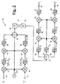
- mixer 43 and filter 45 After filtering with bandpass filters 47 and 48 tuned to this same intermediate frequency f i , mixer 43 and filter 45, in combination, recover signal f 1 , which is then passed to the combiner 18 as in Fig. 1.
- the diversity signal f 1 ' is handled differently.
- the intermediate frequency f i is made small.
- the main signal f 1 provided through filter 45, is close in frequency to the signal f 1 '-2f i , provided through filter 46 and conveying the information contained within the diversity signal f 1 '.
- the frequency f 1 and the frequency of the signal f 1 '-2f i should be made to be far enough apart so as to be easily filtered with RF filters, which are usually relatively low cost.
- the combiner 18 combines the three signals f 1 , f LO , and f 1 '-2f i and provides the combined signal to the optical transmitter 19, which converts the RF signal to a light signal and feeds to the optical fiber 11.
- a photodetector 20 demodulates the light signal to produce an RF signal corresponding to the output of the combiner 18.
- This combined RF signal is fed to the splitter 22.
- the splitter 22 provides the combined RF signal to each of three tuned filters 50, 51, and 52.
- Bandpass filter 50 is tuned to pass the signal f 1 ; filter 51 is tuned to pass the signal f LO ; and filter 52 is tuned to pass the signal f 1 '-2f i '.
- the signal f i is then provided to a mixer 60, which combines f i with the signal f LO , provided by the filter 51, to provide an output with a frequency component at f 1 . That component is extracted by providing the output of the mixer 60 to filter 46, tuned to frequency f 1 .
- the extracted signal f 1 is provided at output 32.
- the same series of operations is carried out for the diversity signal imbedded in the signal f 1 '-2f i provided to mixer 56 along with signal f LO .
- the signal f i ' in turn is provided to the mixer 61 along with signal f LO .
- the output of mixer 61 is then provided to filter 63 tuned to frequency f 1 to provide the diversity signal f 1 '.
- the hardware for treating the main signal f 1 is identical to the hardware for treating the diversity signal f 1 ' with the exception that the two filters 46 and 52 for treating the diversity signal are tuned to lower frequencies than the corresponding filters 45 and 50 for treating the main signal. All other equipment is the same.
- the local oscillator frequency can be generated by a phase-locked loop pre-steered to be near the frequency f LO .
- a phase-locked loop in this context is known in the art.
- the signals f 1 and f 1 ' can be different signals at the same center frequency.
- the present invention is of use in transmitting any two signals of the same center frequency, not just a main signal and its diversity signal.
- small changes in the frequency f LO of the local oscillator do not degrade performance of an apparatus according to the present invention because the signal f LO is first subtracted to produce the intermediate frequency signal f 1 -f LO and then added back to produce the original main signal f 1 .
- Fig. 1 and Fig. 2 provide only the elements essential to practice the present invention.
- an apparatus according to the present invention would include additional components, such as amplifiers and automatic gain controllers; all of which are well known to one of ordinary skill in the art.
- the packaging means uses an oscillator signal to separate in frequency the two arriving signals and to create a single, combined signal that includes the oscillator signal.
- the combined signal is conveyed by the single transmission medium to the un-packaging means, which extracts from the combined signal the two arriving signals and un-shifts one or more of the two arriving signals so that both are again at the original, same center frequency. Because the un-packaging means extracts from the combined signal the same oscillator signal used by the packaging means, the un-shifting by the un-packaging means is performed precisely, avoiding distortion.
Claims (8)
- Dispositif destiné à la communication simultanée via un milieu de transmission unique de deux signaux entrants simultanés présentant substantiellement la même fréquence centrale, à l'aide d'un signal de mélange fourni par un oscillateur, le dispositif étant caractérisé en ce qu'il comprend :a) un moyen d'encapsulation, réactif aux deux signaux entrants, destiné à décaler en fréquence l'un des deux signaux entrants en fonction du signal de mélange afin de fournir au milieu de transmission un signal combiné composé du signal entrant décalé, de l'autre signal entrant et du signal de mélange ; etb) un moyen de désencapsulation, réactif au signal combiné, destiné à extraire le signal de mélange, le signal entrant décalé ainsi que l'autre signal entrant, à rétablir à la fréquence centrale initiale le signal entrant décalé en fonction du signal de mélange extrait, et à fournir l'autre signal entrant et le signal entrant non décalé.
- Dispositif selon la revendication 1, dans lequel le milieu de transmission est une fibre optique.
- Dispositif selon la revendication 2, dans lequel la fréquence centrale est une radiofréquence.
- Dispositif selon la revendication 3, dans lequel le moyen d'encapsulation est caractérisé en ce qu'il comprend :a) un mélangeur, réactif à l'un des signaux entrants et au signal de mélange, destiné à fournir un signal correspondant à la multiplication du signal de mélange et du signal entrant, afin de générer un signal de sortie ayant une composante de fréquence à une fréquence décalée, la fréquence décalée étant égale à la fréquence centrale moins la fréquence du signal de mélange ;b) un filtre, réactif au signal de sortie du mélangeur et accordé sur la fréquence décalée, destiné à fournir le signal entrant décalé; etc) un multiplexeur, réactif au signal de mélange, au signal entrant décalé et à l'autre signal entrant, destiné à générer un signal combiné.
- Dispositif selon la revendication 4, dans lequel le moyen de désencapsulation est caractérisé en ce qu'il comprend :a) un diviseur, réactif au signal combiné, destiné à fournir le signal combiné au niveau des trois sorties du diviseur ;b) un filtre passe-bande substantiellement accordé sur la fréquence centrale, réactif au signal combiné fourni au niveau de l'une des sorties du diviseur, et destiné à fournir l'autre signal entrant ;c) un filtre passe-bande substantiellement accordé sur la fréquence de mélange, réactif au signal combiné fourni au niveau de l'une des sorties du diviseur, et destiné à fournir le signal de mélange ;d) un filtre passe-bande substantiellement accordé sur la fréquence décalée, réactif au signal combiné fourni au niveau de l'une des sorties du diviseur, et destiné à fournir le signal entrant décalé ;e) un mélangeur, réactif au signal décalé filtré et au signal de mélange, destiné à générer un signal ayant une composante de fréquence égale à la fréquence centrale initiale ; etf) un filtre passe-bande substantiellement accordé sur la fréquence centrale, réactif au signal de mélange, et destiné à fournir le signal entrant non décalé.
- Dispositif destiné à la communication simultanée via un milieu de transmission unique de deux signaux entrants simultanés présentant substantiellement la même fréquence centrale, à l'aide d'un signal de mélange fourni par un oscillateur, le dispositif étant caractérisé en ce qu'il comprend :a) une source pour le signal de mélange à une fréquence de mélange ;b) un moyen destiné à décaler en fréquence l'un des deux signaux entrants selon une valeur fonction de la fréquence de mixage, afin de fournir un signal décalé ;c) un moyen destiné à combiner le signal de mélange, le signal décalé et l'autre signal entrant, afin de fournir un signal combiné pour la communication via le milieu de transmission ;d) un moyen réactif au signal combiné transmis, destiné à fournir trois échantillons du signal combiné transmis ;e) un moyen destiné à extraire le signal de mélange de l'un des échantillons du signal combiné transmis ;f) un moyen destiné à extraire le signal décalé de l'un des autres échantillons du signal combiné transmis ;g) un moyen destiné à rétablir le signal décalé extrait au niveau de la fréquence central, à l'aide du signal de mélange extrait, afin de fournir un signal non décalé ; eth) un moyen destiné à extraire l'autre signal entrant de l'un des autres échantillons du signal combiné transmis.
- Dispositif selon la revendication 6, dans lequel le milieu de transmission est une fibre optique.
- Dispositif selon la revendication 7, dans lequel la fréquence centrale est une radiofréquence.
Applications Claiming Priority (2)
| Application Number | Priority Date | Filing Date | Title |
|---|---|---|---|
| US09/108,627 US6268946B1 (en) | 1998-07-01 | 1998-07-01 | Apparatus for communicating diversity signals over a transmission medium |
| US108627 | 1998-07-01 |
Publications (3)
| Publication Number | Publication Date |
|---|---|
| EP0969611A2 EP0969611A2 (fr) | 2000-01-05 |
| EP0969611A3 EP0969611A3 (fr) | 2003-11-05 |
| EP0969611B1 true EP0969611B1 (fr) | 2005-11-30 |
Family
ID=22323235
Family Applications (1)
| Application Number | Title | Priority Date | Filing Date |
|---|---|---|---|
| EP99440141A Expired - Lifetime EP0969611B1 (fr) | 1998-07-01 | 1999-06-11 | Appareil permettant de communiquer des signaux en diversité par un milieu de transmission |
Country Status (4)
| Country | Link |
|---|---|
| US (1) | US6268946B1 (fr) |
| EP (1) | EP0969611B1 (fr) |
| CA (1) | CA2270608C (fr) |
| DE (1) | DE69928604T2 (fr) |
Families Citing this family (60)
| Publication number | Priority date | Publication date | Assignee | Title |
|---|---|---|---|---|
| US6538781B1 (en) * | 1997-02-25 | 2003-03-25 | John Beierle | Multimedia distribution system using fiber optic lines |
| US7224896B1 (en) | 1997-02-25 | 2007-05-29 | Telesector Resources Group, Inc. | Methods and apparatus for generating local oscillation signals |
| US7228072B2 (en) | 2001-10-16 | 2007-06-05 | Telefonaktiebolaget Lm Ericsson (Publ) | System and method for integrating a fiber optic fixed access network and a fiber optic radio access network |
| KR100438177B1 (ko) * | 2001-12-04 | 2004-07-01 | 엘지전자 주식회사 | 억세스 포인트의 신호 처리 장치 및 방법 |
| DE10247149A1 (de) * | 2002-10-09 | 2004-04-22 | Leopold Kostal Gmbh & Co Kg | Verfahren zum Übertragen eines Datenprotokolls auf einer HF-Funkstrecke |
| US20070248358A1 (en) * | 2006-04-19 | 2007-10-25 | Michael Sauer | Electrical-optical cable for wireless systems |
| US7495560B2 (en) * | 2006-05-08 | 2009-02-24 | Corning Cable Systems Llc | Wireless picocellular RFID systems and methods |
| US8472767B2 (en) * | 2006-05-19 | 2013-06-25 | Corning Cable Systems Llc | Fiber optic cable and fiber optic cable assembly for wireless access |
| US20070292136A1 (en) * | 2006-06-16 | 2007-12-20 | Michael Sauer | Transponder for a radio-over-fiber optical fiber cable |
| US7627250B2 (en) * | 2006-08-16 | 2009-12-01 | Corning Cable Systems Llc | Radio-over-fiber transponder with a dual-band patch antenna system |
| US7787823B2 (en) * | 2006-09-15 | 2010-08-31 | Corning Cable Systems Llc | Radio-over-fiber (RoF) optical fiber cable system with transponder diversity and RoF wireless picocellular system using same |
| US7848654B2 (en) * | 2006-09-28 | 2010-12-07 | Corning Cable Systems Llc | Radio-over-fiber (RoF) wireless picocellular system with combined picocells |
| US8873585B2 (en) | 2006-12-19 | 2014-10-28 | Corning Optical Communications Wireless Ltd | Distributed antenna system for MIMO technologies |
| US8111998B2 (en) * | 2007-02-06 | 2012-02-07 | Corning Cable Systems Llc | Transponder systems and methods for radio-over-fiber (RoF) wireless picocellular systems |
| US20100054746A1 (en) | 2007-07-24 | 2010-03-04 | Eric Raymond Logan | Multi-port accumulator for radio-over-fiber (RoF) wireless picocellular systems |
| US8175459B2 (en) | 2007-10-12 | 2012-05-08 | Corning Cable Systems Llc | Hybrid wireless/wired RoF transponder and hybrid RoF communication system using same |
| US8644844B2 (en) | 2007-12-20 | 2014-02-04 | Corning Mobileaccess Ltd. | Extending outdoor location based services and applications into enclosed areas |
| WO2010090999A1 (fr) | 2009-02-03 | 2010-08-12 | Corning Cable Systems Llc | Systèmes d'antennes réparties basés sur les fibres optiques, composants et procédés associés destinés à leur surveillance et à leur configuration |
| JP5480916B2 (ja) | 2009-02-03 | 2014-04-23 | コーニング ケーブル システムズ リミテッド ライアビリティ カンパニー | 光ファイバベースの分散型アンテナシステム、構成要素、及びその較正のための関連の方法 |
| US9673904B2 (en) | 2009-02-03 | 2017-06-06 | Corning Optical Communications LLC | Optical fiber-based distributed antenna systems, components, and related methods for calibration thereof |
| US8548330B2 (en) | 2009-07-31 | 2013-10-01 | Corning Cable Systems Llc | Sectorization in distributed antenna systems, and related components and methods |
| US8280259B2 (en) | 2009-11-13 | 2012-10-02 | Corning Cable Systems Llc | Radio-over-fiber (RoF) system for protocol-independent wired and/or wireless communication |
| US8275265B2 (en) * | 2010-02-15 | 2012-09-25 | Corning Cable Systems Llc | Dynamic cell bonding (DCB) for radio-over-fiber (RoF)-based networks and communication systems and related methods |
| US20110268446A1 (en) | 2010-05-02 | 2011-11-03 | Cune William P | Providing digital data services in optical fiber-based distributed radio frequency (rf) communications systems, and related components and methods |
| US9525488B2 (en) | 2010-05-02 | 2016-12-20 | Corning Optical Communications LLC | Digital data services and/or power distribution in optical fiber-based distributed communications systems providing digital data and radio frequency (RF) communications services, and related components and methods |
| EP2606707A1 (fr) | 2010-08-16 | 2013-06-26 | Corning Cable Systems LLC | Grappes d'antennes distantes, et systèmes, composants et procédés associés adaptés pour prendre en charge une propagation de signaux de données numériques entre des unités d'antennes distantes |
| US9252874B2 (en) | 2010-10-13 | 2016-02-02 | Ccs Technology, Inc | Power management for remote antenna units in distributed antenna systems |
| EP2678972B1 (fr) | 2011-02-21 | 2018-09-05 | Corning Optical Communications LLC | Fourniture de services de données numériques comme signaux électriques et télécommunications radiofréquence (rf) sur une fibre optique dans des systèmes de télécommunications répartis, et composants et procédés associés |
| EP2702710A4 (fr) | 2011-04-29 | 2014-10-29 | Corning Cable Sys Llc | Détermination de temps de propagation de communications dans systèmes d'antennes distribuées, et composants, systèmes et procédés associés |
| WO2012148940A1 (fr) | 2011-04-29 | 2012-11-01 | Corning Cable Systems Llc | Systèmes, procédés et dispositifs pour augmenter la puissance radiofréquence (rf) dans systèmes d'antennes distribuées |
| EP2832012A1 (fr) | 2012-03-30 | 2015-02-04 | Corning Optical Communications LLC | Réduction d'un brouillage lié à la position dans des systèmes d'antennes distribuées fonctionnant selon une configuration à entrées multiples et à sorties multiples (mimo), et composants, systèmes et procédés associés |
| WO2013162988A1 (fr) | 2012-04-25 | 2013-10-31 | Corning Cable Systems Llc | Architectures de système d'antenne distribué |
| WO2014024192A1 (fr) | 2012-08-07 | 2014-02-13 | Corning Mobile Access Ltd. | Distribution de services de gestion multiplexés par répartition dans le temps (tdm) dans un système d'antennes distribuées, et composants, systèmes et procédés associés |
| US9455784B2 (en) | 2012-10-31 | 2016-09-27 | Corning Optical Communications Wireless Ltd | Deployable wireless infrastructures and methods of deploying wireless infrastructures |
| CN105308876B (zh) | 2012-11-29 | 2018-06-22 | 康宁光电通信有限责任公司 | 分布式天线系统中的远程单元天线结合 |
| US9647758B2 (en) | 2012-11-30 | 2017-05-09 | Corning Optical Communications Wireless Ltd | Cabling connectivity monitoring and verification |
| CN105452951B (zh) | 2013-06-12 | 2018-10-19 | 康宁光电通信无线公司 | 电压控制式光学定向耦合器 |
| EP3008828B1 (fr) | 2013-06-12 | 2017-08-09 | Corning Optical Communications Wireless Ltd. | Duplexage par répartition temporelle (tdd) dans des systèmes de communication répartis, comprenant des systèmes d'antenne répartis (das) |
| US9247543B2 (en) | 2013-07-23 | 2016-01-26 | Corning Optical Communications Wireless Ltd | Monitoring non-supported wireless spectrum within coverage areas of distributed antenna systems (DASs) |
| US9661781B2 (en) | 2013-07-31 | 2017-05-23 | Corning Optical Communications Wireless Ltd | Remote units for distributed communication systems and related installation methods and apparatuses |
| US9385810B2 (en) | 2013-09-30 | 2016-07-05 | Corning Optical Communications Wireless Ltd | Connection mapping in distributed communication systems |
| US9178635B2 (en) | 2014-01-03 | 2015-11-03 | Corning Optical Communications Wireless Ltd | Separation of communication signal sub-bands in distributed antenna systems (DASs) to reduce interference |
| US9775123B2 (en) | 2014-03-28 | 2017-09-26 | Corning Optical Communications Wireless Ltd. | Individualized gain control of uplink paths in remote units in a distributed antenna system (DAS) based on individual remote unit contribution to combined uplink power |
| US9357551B2 (en) | 2014-05-30 | 2016-05-31 | Corning Optical Communications Wireless Ltd | Systems and methods for simultaneous sampling of serial digital data streams from multiple analog-to-digital converters (ADCS), including in distributed antenna systems |
| US9525472B2 (en) | 2014-07-30 | 2016-12-20 | Corning Incorporated | Reducing location-dependent destructive interference in distributed antenna systems (DASS) operating in multiple-input, multiple-output (MIMO) configuration, and related components, systems, and methods |
| US9730228B2 (en) | 2014-08-29 | 2017-08-08 | Corning Optical Communications Wireless Ltd | Individualized gain control of remote uplink band paths in a remote unit in a distributed antenna system (DAS), based on combined uplink power level in the remote unit |
| US9602210B2 (en) | 2014-09-24 | 2017-03-21 | Corning Optical Communications Wireless Ltd | Flexible head-end chassis supporting automatic identification and interconnection of radio interface modules and optical interface modules in an optical fiber-based distributed antenna system (DAS) |
| US9420542B2 (en) | 2014-09-25 | 2016-08-16 | Corning Optical Communications Wireless Ltd | System-wide uplink band gain control in a distributed antenna system (DAS), based on per band gain control of remote uplink paths in remote units |
| US10659163B2 (en) | 2014-09-25 | 2020-05-19 | Corning Optical Communications LLC | Supporting analog remote antenna units (RAUs) in digital distributed antenna systems (DASs) using analog RAU digital adaptors |
| WO2016071902A1 (fr) | 2014-11-03 | 2016-05-12 | Corning Optical Communications Wireless Ltd. | Antennes planes monopôles multibandes configurées pour faciliter une isolation radiofréquence (rf) améliorée dans un système d'antennes entrée multiple sortie multiple (mimo) |
| WO2016075696A1 (fr) | 2014-11-13 | 2016-05-19 | Corning Optical Communications Wireless Ltd. | Systèmes d'antennes distribuées (das) analogiques prenant en charge une distribution de signaux de communications numériques interfacés provenant d'une source de signaux numériques et de signaux de communications radiofréquences (rf) analogiques |
| US9729267B2 (en) | 2014-12-11 | 2017-08-08 | Corning Optical Communications Wireless Ltd | Multiplexing two separate optical links with the same wavelength using asymmetric combining and splitting |
| WO2016098111A1 (fr) | 2014-12-18 | 2016-06-23 | Corning Optical Communications Wireless Ltd. | Modules d'interface numérique-analogique (daim) pour une distribution flexible de signaux de communications numériques et/ou analogiques dans des systèmes étendus d'antennes distribuées analogiques (das) |
| EP3235336A1 (fr) | 2014-12-18 | 2017-10-25 | Corning Optical Communications Wireless Ltd. | Modules d'interface numérique (dim) pour une distribution flexible de signaux de communication numériques et/ou analogiques dans des réseaux d'antennes distribuées (das) analogiques étendus |
| US20160249365A1 (en) | 2015-02-19 | 2016-08-25 | Corning Optical Communications Wireless Ltd. | Offsetting unwanted downlink interference signals in an uplink path in a distributed antenna system (das) |
| US9681313B2 (en) | 2015-04-15 | 2017-06-13 | Corning Optical Communications Wireless Ltd | Optimizing remote antenna unit performance using an alternative data channel |
| US9948349B2 (en) | 2015-07-17 | 2018-04-17 | Corning Optical Communications Wireless Ltd | IOT automation and data collection system |
| US10560214B2 (en) | 2015-09-28 | 2020-02-11 | Corning Optical Communications LLC | Downlink and uplink communication path switching in a time-division duplex (TDD) distributed antenna system (DAS) |
| US10236924B2 (en) | 2016-03-31 | 2019-03-19 | Corning Optical Communications Wireless Ltd | Reducing out-of-channel noise in a wireless distribution system (WDS) |
| US20190107617A1 (en) * | 2017-10-06 | 2019-04-11 | Rf Venue, Inc. | Diversity fin antenna |
Family Cites Families (11)
| Publication number | Priority date | Publication date | Assignee | Title |
|---|---|---|---|---|
| US3860873A (en) * | 1971-10-01 | 1975-01-14 | Tape Athon Corp | Fm transmission system |
| US4289373A (en) * | 1978-08-17 | 1981-09-15 | Nippon Electric Co., Ltd. | Bidirectional optical fiber transmission system |
| US4323731A (en) * | 1978-12-18 | 1982-04-06 | Harris Corporation | Variable-angle, multiple channel amplitude modulation system |
| US4225751A (en) * | 1978-12-18 | 1980-09-30 | Harris Corporation | Variable-angle, multiple channel amplitude modulation system |
| US5067173A (en) * | 1990-12-20 | 1991-11-19 | At&T Bell Laboratories | Microcellular communications system using space diversity reception |
| US5321849A (en) * | 1991-05-22 | 1994-06-14 | Southwestern Bell Technology Resources, Inc. | System for controlling signal level at both ends of a transmission link based on a detected valve |
| US5339184A (en) * | 1992-06-15 | 1994-08-16 | Gte Laboratories Incorporated | Fiber optic antenna remoting for multi-sector cell sites |
| CN1056255C (zh) * | 1993-01-30 | 2000-09-06 | 汤姆森电子消费品公司 | 变频器 |
| US5742583A (en) * | 1994-11-03 | 1998-04-21 | Omnipoint Corporation | Antenna diversity techniques |
| US6075823A (en) * | 1997-04-09 | 2000-06-13 | Nec Corporation | Apparatus and method of achieving improved diversity reception in a digital radio communications system |
| US6018514A (en) * | 1998-06-29 | 2000-01-25 | Motorola, Inc. | Apparatus and method for protecting a communication device operating in an undesirable environment |
-
1998
- 1998-07-01 US US09/108,627 patent/US6268946B1/en not_active Expired - Lifetime
-
1999
- 1999-05-03 CA CA002270608A patent/CA2270608C/fr not_active Expired - Fee Related
- 1999-06-11 DE DE69928604T patent/DE69928604T2/de not_active Expired - Lifetime
- 1999-06-11 EP EP99440141A patent/EP0969611B1/fr not_active Expired - Lifetime
Also Published As
| Publication number | Publication date |
|---|---|
| US6268946B1 (en) | 2001-07-31 |
| CA2270608C (fr) | 2004-09-07 |
| DE69928604T2 (de) | 2006-08-10 |
| CA2270608A1 (fr) | 2000-01-01 |
| EP0969611A3 (fr) | 2003-11-05 |
| DE69928604D1 (de) | 2006-01-05 |
| EP0969611A2 (fr) | 2000-01-05 |
Similar Documents
| Publication | Publication Date | Title |
|---|---|---|
| EP0969611B1 (fr) | Appareil permettant de communiquer des signaux en diversité par un milieu de transmission | |
| US4928317A (en) | Radio-optical transmission system, in particular for space telecommunications | |
| US6868254B2 (en) | Repeater with diversity transmission | |
| US8351796B2 (en) | Optical low-noise block downconverter, multiple dwelling unit, and related satellite television system | |
| EP1330059A4 (fr) | Dispositif de radiocommunication, dispositif d'emission et dispositif de reception | |
| JPWO2006009197A1 (ja) | 光信号伝送のための装置、システムおよび方法 | |
| GB1599616A (en) | Demodulating system for an auxilary channel in a straight-through radio frequency repeater | |
| EP0680156B1 (fr) | Appareil radio et procédé de transmission correspondant | |
| EP0996241A1 (fr) | Systeme de communication mobile | |
| US4349919A (en) | Transmitter/receivers capable of contemporaneous transmission/reception | |
| US4385378A (en) | High power multiplexer for dual polarized frequency reuse earth stations | |
| KR100788872B1 (ko) | 송수신 안테나 분리를 이용한 tdd용 rf 중계기 | |
| US7039357B2 (en) | Diversity coverage | |
| GB2052196A (en) | Demodulators | |
| US5084779A (en) | Transmitter and transceiver for a coherent optical system | |
| EP2560236B1 (fr) | Appareil permettant de communiquer des signaux multiples depuis plusieurs antennes sur un seul câble | |
| US7509049B2 (en) | System for selectively combining satellite signals sent to a user through an optical fiber | |
| US7747284B2 (en) | Terminal device for a bi-directional radio relay link | |
| JPH07162334A (ja) | 二重データ伝送方法 | |
| JPH06169272A (ja) | ダイバーシチ信号伝送方式 | |
| JP2513324B2 (ja) | 両偏波伝送装置 | |
| GB2035013A (en) | Splitter/combiner network | |
| CN114553253A (zh) | 同步传输多种信号的多通道通信装置 | |
| JPH05153013A (ja) | 多重無線システム | |
| JPS6124339A (ja) | 交差偏波補償方式 |
Legal Events
| Date | Code | Title | Description |
|---|---|---|---|
| PUAI | Public reference made under article 153(3) epc to a published international application that has entered the european phase |
Free format text: ORIGINAL CODE: 0009012 |
|
| AK | Designated contracting states |
Kind code of ref document: A2 Designated state(s): AT BE CH CY DE DK ES FI FR GB GR IE IT LI LU MC NL PT SE |
|
| AX | Request for extension of the european patent |
Free format text: AL;LT;LV;MK;RO;SI |
|
| PUAL | Search report despatched |
Free format text: ORIGINAL CODE: 0009013 |
|
| RIC1 | Information provided on ipc code assigned before grant |
Ipc: 7H 04B 7/08 B Ipc: 7H 04B 10/12 B Ipc: 7H 04B 7/12 A |
|
| AK | Designated contracting states |
Kind code of ref document: A3 Designated state(s): AT BE CH CY DE DK ES FI FR GB GR IE IT LI LU MC NL PT SE |
|
| AX | Request for extension of the european patent |
Extension state: AL LT LV MK RO SI |
|
| 17P | Request for examination filed |
Effective date: 20031209 |
|
| RAP1 | Party data changed (applicant data changed or rights of an application transferred) |
Owner name: RADIO FREQUENCY SYSTEMS, INC. |
|
| AKX | Designation fees paid |
Designated state(s): DE FR GB IT SE |
|
| GRAP | Despatch of communication of intention to grant a patent |
Free format text: ORIGINAL CODE: EPIDOSNIGR1 |
|
| GRAS | Grant fee paid |
Free format text: ORIGINAL CODE: EPIDOSNIGR3 |
|
| GRAA | (expected) grant |
Free format text: ORIGINAL CODE: 0009210 |
|
| AK | Designated contracting states |
Kind code of ref document: B1 Designated state(s): DE FR GB IT SE |
|
| REG | Reference to a national code |
Ref country code: GB Ref legal event code: FG4D |
|
| REF | Corresponds to: |
Ref document number: 69928604 Country of ref document: DE Date of ref document: 20060105 Kind code of ref document: P |
|
| PG25 | Lapsed in a contracting state [announced via postgrant information from national office to epo] |
Ref country code: SE Free format text: LAPSE BECAUSE OF FAILURE TO SUBMIT A TRANSLATION OF THE DESCRIPTION OR TO PAY THE FEE WITHIN THE PRESCRIBED TIME-LIMIT Effective date: 20060228 |
|
| ET | Fr: translation filed | ||
| PLBE | No opposition filed within time limit |
Free format text: ORIGINAL CODE: 0009261 |
|
| STAA | Information on the status of an ep patent application or granted ep patent |
Free format text: STATUS: NO OPPOSITION FILED WITHIN TIME LIMIT |
|
| 26N | No opposition filed |
Effective date: 20060831 |
|
| REG | Reference to a national code |
Ref country code: FR Ref legal event code: TP Owner name: ALCATEL LUCENT, FR Effective date: 20130628 |
|
| REG | Reference to a national code |
Ref country code: GB Ref legal event code: 732E Free format text: REGISTERED BETWEEN 20130822 AND 20130828 |
|
| REG | Reference to a national code |
Ref country code: FR Ref legal event code: GC Effective date: 20130920 |
|
| REG | Reference to a national code |
Ref country code: FR Ref legal event code: RG Effective date: 20141016 |
|
| REG | Reference to a national code |
Ref country code: FR Ref legal event code: PLFP Year of fee payment: 17 |
|
| PGFP | Annual fee paid to national office [announced via postgrant information from national office to epo] |
Ref country code: DE Payment date: 20150619 Year of fee payment: 17 Ref country code: GB Payment date: 20150618 Year of fee payment: 17 |
|
| PGFP | Annual fee paid to national office [announced via postgrant information from national office to epo] |
Ref country code: FR Payment date: 20150619 Year of fee payment: 17 Ref country code: IT Payment date: 20150622 Year of fee payment: 17 |
|
| REG | Reference to a national code |
Ref country code: DE Ref legal event code: R119 Ref document number: 69928604 Country of ref document: DE |
|
| GBPC | Gb: european patent ceased through non-payment of renewal fee |
Effective date: 20160611 |
|
| REG | Reference to a national code |
Ref country code: FR Ref legal event code: ST Effective date: 20170228 |
|
| PG25 | Lapsed in a contracting state [announced via postgrant information from national office to epo] |
Ref country code: DE Free format text: LAPSE BECAUSE OF NON-PAYMENT OF DUE FEES Effective date: 20170103 Ref country code: FR Free format text: LAPSE BECAUSE OF NON-PAYMENT OF DUE FEES Effective date: 20160630 |
|
| PG25 | Lapsed in a contracting state [announced via postgrant information from national office to epo] |
Ref country code: GB Free format text: LAPSE BECAUSE OF NON-PAYMENT OF DUE FEES Effective date: 20160611 |
|
| PG25 | Lapsed in a contracting state [announced via postgrant information from national office to epo] |
Ref country code: IT Free format text: LAPSE BECAUSE OF NON-PAYMENT OF DUE FEES Effective date: 20160611 |