EP0969544B1 - Composite filter, duplexer and communication apparatus - Google Patents
Composite filter, duplexer and communication apparatus Download PDFInfo
- Publication number
- EP0969544B1 EP0969544B1 EP99112413A EP99112413A EP0969544B1 EP 0969544 B1 EP0969544 B1 EP 0969544B1 EP 99112413 A EP99112413 A EP 99112413A EP 99112413 A EP99112413 A EP 99112413A EP 0969544 B1 EP0969544 B1 EP 0969544B1
- Authority
- EP
- European Patent Office
- Prior art keywords
- dielectric
- filters
- dielectric block
- filter
- duplexer
- Prior art date
- Legal status (The legal status is an assumption and is not a legal conclusion. Google has not performed a legal analysis and makes no representation as to the accuracy of the status listed.)
- Expired - Lifetime
Links
Images

Classifications
-
- H—ELECTRICITY
- H01—ELECTRIC ELEMENTS
- H01P—WAVEGUIDES; RESONATORS, LINES, OR OTHER DEVICES OF THE WAVEGUIDE TYPE
- H01P1/00—Auxiliary devices
- H01P1/20—Frequency-selective devices, e.g. filters
- H01P1/213—Frequency-selective devices, e.g. filters combining or separating two or more different frequencies
- H01P1/2136—Frequency-selective devices, e.g. filters combining or separating two or more different frequencies using comb or interdigital filters; using cascaded coaxial cavities
Definitions
- the present invention relates to a composite filter and a duplexer, in which a plurality of filters is formed in a single dielectric block, and a communication apparatus using the same, used in the microwave band of a mobile phone or the like.
- a duplexer in which resonators forming a transmitting-side filter and resonators forming a receiving-side filter are integrally molded in a single dielectric block formed of dielectric materials with an equivalent dielectric constant, is known.
- Such a duplexer is formed by disposing a plurality of resonator holes having inner conductors on the inner peripheral surfaces thereof between opposing end surfaces of the dielectric block having an outer conductor on an external surface thereof, in which each of the inner conductors is formed for serving as a one-end open resonator which is separated from the outer conductor on one end, whereas it is short-circuited with the outer conductor on the other end.
- the transmitting-side filter and the receiving-side filter have different frequencies in such a conventional duplexer, the lengths of resonators forming the respective filters are naturally different, in which there is a difference in the length of the resonator length direction between the portion forming the transmitting-side filter and the portion forming the receiving-side filter, whereby the unit has a configuration with a step portion on the outline of the dielectric block.
- a central frequency of the transmitting-side filter is 836.5 MHz
- a central frequency of the receiving-side filter is 881.5 MHz
- the resonator length of the transmitting-side filter is 9.34 mm
- the resonator length of the receiving-side filter is 8.86 mm, resulting in generating a step, which is 0.48 mm, on the outline of the dielectric block.
- a duplexer in which a portion of an inner conductor is eliminated to form an open end of a resonator inside a dielectric block, and adjustment of a location for forming the open end allows a transmitting-side filter and a receiving-side filter to be formed in a single dielectric block formed of materials having the equivalent dielectric constant, with no steps on its outline.
- the open end of a resonator in which the open end of a resonator is formed inside the dielectric block, when the difference between the frequency of the transmitting-side filter and that of the receiving-side filter is large, the open end (that is, a portion where no inner conductor is formed) of the resonator forming the filter of a lower frequency is needed to be formed in a location which is very deeply recessed from the open-side end surface of the dielectric block, leading to difficulty in forming the non-inner-conductor portion or forming with high precision in a specified location.
- EP-A-0 508 812 relates to a dielectric filter comprising several ceramic resonator blocks in contiguous relationship.
- the individual resonator blocks are made of different ceramic materials having respectively different dielectric constants. Consequently, the resonator blocks may all have the same physical height, while having different resonant frequencies. Thus, an optimum physical size may be selected for the resonator blocks, particularly with regard to packing density.
- preferred embodiments of the present invention provide a composite filter, which is low-cost, small, and has satisfactory characteristics.
- One preferred embodiment of the present invention provides a composite filter comprising: a single unitary dielectric block having an outer conductor on the external surfaces thereof; a plurality of inner conductors disposed in the dielectric block; a plurality of filters with different frequencies respectively comprising resonators made of at least one of said inner conductor; a first portion of said dielectric block constituting at least one of said filter comprising a first dielectric material; a second portion of said dielectric block constituting the other one of said filter comprising a second dielectric material; and the dielectric constant of said first dielectric material and said second dielectric material being different from each other.
- the above described composite filter may be a duplexer in which at least one of said filter comprising said first portion of said dielectric block and said first dielectric material is a transmitting-side filter; and at least one of said filter comprising said second portion of said dielectric block and said second dielectric material is a receiving-side filter.
- Another preferred embodiment of the present invention provides a communication apparatus comprising: a transmission circuit; a reception circuit; an antenna; the above described composite filter or duplexer: said at least one of said filter comprising said first portion of said dielectric block and said first dielectric material having a first input and a first output, said first input being connected to said transmission circuit, and said first output being connected to said antenna; and the other one of said filter comprising said second portion of said dielectric block and said second dielectric material having a second input and a second output, said second input being connected to said antenna, and said second output being connected to said reception circuit.
- a plurality of filters with different frequencies are formed in the single unitary dielectric block, in which the portion forming at least one of the filters is formed of a dielectric material having a dielectric constant different from that of the portion forming the other filter.
- the portion forming at least one of the filters is formed of a dielectric material having a dielectric constant different from that of the portion forming the other filter.
- the present invention is achieved by using dielectric materials, in which a dielectric constant of the portion forming a lower-frequency filter is larger than that of the portion forming a high-frequency filter. That is, the single dielectric block including a plurality of filters with different frequencies can be made into rectangular parallelepiped configuration having no steps.
- each resonator when the inner conductor is eliminated to form an open end, the open end of each resonator can be formed substantially in the same position near the open-side end surface, so that formation of the non-inner-conductor portion can be easily conducted with high precision.
- combining the method of using dielectric materials having different dielectric constants in the present invention with other designing methods such as changing the position of the open end can enhance freedom in design, so that various kinds of characteristics can be easily obtained by using a single dielectric block without any step formed.
- a plurality of filters are formed in the single unitary dielectric block integrally molded and burned, in which the number of components are less than that in a unit with each filter formed by an individual dielectric block so as to permit easy handling, or to make it unnecessary to bond a plurality of the filters together by soldering or the like, leading to cost reduction.
- the communication apparatus according to the present invention includes the composite filter or the duplexer having the above-described characteristics, low cost, miniaturization, and satisfactory characteristics can be achieved.
- the duplexer employed in the first preferred embodiment includes a dielectric block 1 of rectangular parallelepiped configuration formed by integral molding. Seven resonator holes 2a through 2g are formed running through between a pair of opposing end surfaces 1a and 1b of the dielectric block 1, and external coupling holes 5a, 5b, and 5c, and ground holes 6a, 6b, and 6c are formed between the resonator holes 2a and 2b, between the resonator holes 2c and 2d, and between the resonator holes 2f and 2g.
- An outer conductor 4 is formed on the substantially entire external surfaces of the dielectric block 1, and an inner conductor 3 is formed on each of the inner peripheral surfaces of the resonator holes 2a through 2g, the external coupling holes 5a, 5b, and 5c, and the ground holes 6a, 6b, and 6c.
- Each inner conductor 3 inside the resonator holes 2a through 2g is separated from the outer conductor 4 by a non-inner-conductor portion 8 on the side of the open-side end surface 1a, whereas it is electrically connected to the outer conductor 4 on the short-circuited side end surface 1b.
- the open end of a resonator corresponding to each inner conductor 3 of the resonator holes 2a through 2g is formed by each non-inner-conductor portion 8 in the substantially equivalent position deeply recessed from the open-side end surface 1a.
- the non-inner-conductor portion 8 is formed by cutting away and eliminating the inner conductor 3 by a router or the like.
- Input/output electrodes 7a, 7b, and 7c extend over the short-circuited side end surface 1 b and a side surface (a bottom surface) to be electrically connected to the inner conductors 3 of the external resonator holes 5a through 5c, whereas they are separated from the outer conductor 4.
- coupling of the two resonators corresponding to the inner conductors 3 of the resonator holes 2b and 2c permits a transmission filter to be formed, and the transmission filter and a trap (a band elimination filter with a resonator) formed by a resonator corresponding to the inner conductor 3 of the resonator hole 2a comprise a transmitting-side filter.
- coupling of the three resonators corresponding to the inner conductors 3 of the resonator holes 2d, 2e and 2f permits a reception filter to be formed, and the reception filter and a trap formed by a resonator corresponding to the inner conductor 3 of the resonator hole 2g comprise a receiving-side filter.
- the central frequency of the transmission filter is lower than the central frequency of the reception filter.
- the duplexer is surface-mounted in such a manner that the side surfaces (the upper surfaces in Fig. 1), on which the input/output electrodes 7a, 7b, and 7c are formed, are surfaces to be mounted.
- the input/output electrode 7a is a transmission terminal of the transmitting-side filter
- the input/output electrode 7c is a reception terminal of the receiving-side filter
- the input/output electrode 7b is an antenna terminal for common use of an input/output of the transmitting-side filter and the receiving-side filter.
- the left region (first portion), in which the resonator holes 2a through 2c forming the transmitting-side filter are disposed, is formed of a dielectric material with a large dielectric constant
- the right region (a second portion), in which the resonator holes 2d through 2g forming the receiving-side filter are disposed is formed of a dielectric material with a small dielectric constant
- the length of a resonator corresponding to the inner conductor 3 of the respective resonator holes is equivalent. That is, the surface indicated by broken lines in Fig. 1 and Fig. 2 is a boundary surface so as to form the left region and the right region by using a dielectric material with a different dielectric constant.
- the arrangement is such that the central frequency of the transmission filter is 836.5 MHz, the central frequency of the reception filter is 881.5 MHz; in which the left region forming the transmitting-side filter is formed of a dielectric material with a relative dielectric constant ⁇ r of 102.3, while the right region forming the receiving-side filter is formed of a dielectric material with a relative dielectric constant ⁇ r of 92; and the resonator length of the transmitting-side filter and the resonator length of the receiving-side filter are both about 8.86 mm.
- the boundary surface is not limited to the position indicated by the broken lines shown in the figures. It is set near the external coupling hole 5b.
- the configuration and number of the external coupling hole and the ground hole are not limited to the case shown in the figures, and they can be appropriately determined, as needed depending on required characteristics.
- the above described single unitary dielectric body comprising the first portion and the second portion
- at least two green sheets having different dielectric constants to each other are laminated, and, after being subjected to heat press, cut into a molded body.
- organic components of the molded body obtained in the air atmosphere at 500 degrees Centigrade for example
- fired in an oxygen atmosphere at 1350 degrees Centigrade for example
- a sintered body i.e., the single unitary dielectric block.
- the dielectric block with dielectric materials having different dielectric constants permits the configuration of the dielectric block to be of rectangular parallelepiped having no steps, even though the open end of each resonator is formed substantially in the same position. At the same time, miniaturization can be achieved.
- the open end is disposed in a position deeply recessed from the end surface of the dielectric block.
- a duplexer having an arrangement in which the opening surface of a resonator hole is used as the open end may be applicable.
- the present invention can be a more effective method.
- the open end of each resonator can be formed in the substantially equivalent position near the open-side end surface, so that formation of a non-inner-conductor portion can be easily conducted with high precision.
- the dielectric block can be molded without using a metal die with a complicated configuration; processing, assembly, measurement, and mounting after molding can be facilitated; and reduction in molding cost and manufacturing cost can be achieved so as to obtain satisfactory characteristics with less variations.
- the duplexer of the above embodiment has such an arrangement that the two kinds of dielectric materials with different dielectric constants are integrally molded to form the dielectric block, the regions for forming the traps on both sides may also be formed of dielectric materials having dielectric constants.
- the present invention can also be applied to a composite filter, in which a plurality of filters for transmitting two or more kinds of signals with different transmission-band frequencies are formed in a single dielectric block.
- the composite filter and the duplexer according to the present invention are not restricted to the above embodiment, and various modifications are applicable within the range of the scope and the sprit of the invention.
- the resonator hole may be the so-called step hole including a wide inner-diameter portion and a small inner-diameter portion, and regarding coupling between the respective resonators or coupling between the resonators and the external coupling holes, other coupling methods such as a comb-line coupling, or an interdigital coupling may be possible.
- An arrangement in which the external coupling is obtained by a capacity coupling between the input/output electrode and the inner conductor may be possible.
- Fig. 3 shows a structure of a second preferred embodiment of the communication apparatus according to the present invention.
- ANT is an antenna
- DPX is a duplexer
- TX is a transmitting-side filter
- RX is a receiving-side filter.
- the output end of the transmitting-side filter TX is connected to the antenna ANT, and the input end of the same is connected to a transmission circuit, while the input end of the receiving-side filter RX is connected to the antenna ANT, and the output end of the same is connected to a reception circuit, whereby a communication apparatus is formed.
- the duplexer shown in Fig. 1 of the first embodiment can be used as the duplexer DPX.
- Use of the duplexer in accordance with the present invention allows a communication apparatus, which is low cost, small, and satisfactory in the characteristics, to be obtained.
Landscapes
- Control Of Motors That Do Not Use Commutators (AREA)
Description
- The present invention relates to a composite filter and a duplexer, in which a plurality of filters is formed in a single dielectric block, and a communication apparatus using the same, used in the microwave band of a mobile phone or the like.
- Conventionally, a duplexer, in which resonators forming a transmitting-side filter and resonators forming a receiving-side filter are integrally molded in a single dielectric block formed of dielectric materials with an equivalent dielectric constant, is known. Such a duplexer is formed by disposing a plurality of resonator holes having inner conductors on the inner peripheral surfaces thereof between opposing end surfaces of the dielectric block having an outer conductor on an external surface thereof, in which each of the inner conductors is formed for serving as a one-end open resonator which is separated from the outer conductor on one end, whereas it is short-circuited with the outer conductor on the other end.
- Since the transmitting-side filter and the receiving-side filter have different frequencies in such a conventional duplexer, the lengths of resonators forming the respective filters are naturally different, in which there is a difference in the length of the resonator length direction between the portion forming the transmitting-side filter and the portion forming the receiving-side filter, whereby the unit has a configuration with a step portion on the outline of the dielectric block. For example, when a central frequency of the transmitting-side filter is 836.5 MHz, a central frequency of the receiving-side filter is 881.5 MHz, if a dielectric material whose relative dielectric constant εr is 92 is used, the resonator length of the transmitting-side filter is 9.34 mm, and the resonator length of the receiving-side filter is 8.86 mm, resulting in generating a step, which is 0.48 mm, on the outline of the dielectric block.
- Furthermore, conventionally, there is provided a duplexer, in which a portion of an inner conductor is eliminated to form an open end of a resonator inside a dielectric block, and adjustment of a location for forming the open end allows a transmitting-side filter and a receiving-side filter to be formed in a single dielectric block formed of materials having the equivalent dielectric constant, with no steps on its outline. (Japanese Unexamined Patent Publication No. 8-330806)
- However, regarding the former type of the above described prior art duplexer, in which the end of the dielectric block is an open end, when the dielectric block is molded, various kinds of molding metal dies with high precision, having step portions according to the frequency difference between the two filters, are needed, so that die cost and molding cost increase. Additionally, due to its complicated configuration having a step on the outline, looseness and deviation are likely to occur in processing, assembly, measurement, mounting, or the like after molding, so that work such as location determination is complicated so as to increase production cost.
- Meanwhile, as the later type, in the prior art duplexer, in which the open end of a resonator is formed inside the dielectric block, when the difference between the frequency of the transmitting-side filter and that of the receiving-side filter is large, the open end (that is, a portion where no inner conductor is formed) of the resonator forming the filter of a lower frequency is needed to be formed in a location which is very deeply recessed from the open-side end surface of the dielectric block, leading to difficulty in forming the non-inner-conductor portion or forming with high precision in a specified location.
- EP-A-0 508 812 relates to a dielectric filter comprising several ceramic resonator blocks in contiguous relationship. The individual resonator blocks are made of different ceramic materials having respectively different dielectric constants. Consequently, the resonator blocks may all have the same physical height, while having different resonant frequencies. Thus, an optimum physical size may be selected for the resonator blocks, particularly with regard to packing density.
- To overcome the above described problems, preferred embodiments of the present invention provide a composite filter, which is low-cost, small, and has satisfactory characteristics.
- This object is achieved by a composite filter according to
claim 1. - One preferred embodiment of the present invention provides a composite filter comprising: a single unitary dielectric block having an outer conductor on the external surfaces thereof; a plurality of inner conductors disposed in the dielectric block; a plurality of filters with different frequencies respectively comprising resonators made of at least one of said inner conductor; a first portion of said dielectric block constituting at least one of said filter comprising a first dielectric material; a second portion of said dielectric block constituting the other one of said filter comprising a second dielectric material; and the dielectric constant of said first dielectric material and said second dielectric material being different from each other.
- The above described composite filter may be a duplexer in which at least one of said filter comprising said first portion of said dielectric block and said first dielectric material is a transmitting-side filter; and at least one of said filter comprising said second portion of said dielectric block and said second dielectric material is a receiving-side filter.
- Another preferred embodiment of the present invention provides a communication apparatus comprising: a transmission circuit; a reception circuit; an antenna; the above described composite filter or duplexer: said at least one of said filter comprising said first portion of said dielectric block and said first dielectric material having a first input and a first output, said first input being connected to said transmission circuit, and said first output being connected to said antenna; and the other one of said filter comprising said second portion of said dielectric block and said second dielectric material having a second input and a second output, said second input being connected to said antenna, and said second output being connected to said reception circuit.
- In the composite filter or the duplexer having the above described structure, a plurality of filters with different frequencies are formed in the single unitary dielectric block, in which the portion forming at least one of the filters is formed of a dielectric material having a dielectric constant different from that of the portion forming the other filter. In this structure, appropriate selection of a dielectric constant of the portion forming each filter corresponding to the frequency of each filter allows the physical resonator length of each resonator having a different frequency to be made into the equivalent length, even when the open end of each resonator is formed in the same position. More specifically, the present invention is achieved by using dielectric materials, in which a dielectric constant of the portion forming a lower-frequency filter is larger than that of the portion forming a high-frequency filter. That is, the single dielectric block including a plurality of filters with different frequencies can be made into rectangular parallelepiped configuration having no steps.
- In addition, when the inner conductor is eliminated to form an open end, the open end of each resonator can be formed substantially in the same position near the open-side end surface, so that formation of the non-inner-conductor portion can be easily conducted with high precision.
- Furthermore, combining the method of using dielectric materials having different dielectric constants in the present invention with other designing methods such as changing the position of the open end can enhance freedom in design, so that various kinds of characteristics can be easily obtained by using a single dielectric block without any step formed.
- In the composite filter and the duplexer according to the present invention, a plurality of filters are formed in the single unitary dielectric block integrally molded and burned, in which the number of components are less than that in a unit with each filter formed by an individual dielectric block so as to permit easy handling, or to make it unnecessary to bond a plurality of the filters together by soldering or the like, leading to cost reduction.
- Furthermore, since the communication apparatus according to the present invention includes the composite filter or the duplexer having the above-described characteristics, low cost, miniaturization, and satisfactory characteristics can be achieved.
- Other features and advantages of the present invention will become apparent from the following description of the invention which refers to the accompanying drawings.
-
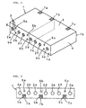
- Fig. 1 is a perspective view of a duplexer according to a first preferred embodiment of the present invention.
- Fig. 2 is a plan view of a short-circuited end surface of the duplexer according to the first preferred embodiment of the present invention.
- Fig. 3 is a block diagram of a communication apparatus according to a second preferred embodiment of the present invention.
-
- Referring to Fig. 1 and Fig. 2, the duplexer employed in the first preferred embodiment includes a
dielectric block 1 of rectangular parallelepiped configuration formed by integral molding. Seven resonator holes 2a through 2g are formed running through between a pair of opposing end surfaces 1a and 1b of thedielectric block 1, andexternal coupling holes ground holes 6a, 6b, and 6c are formed between theresonator holes 2a and 2b, between theresonator holes resonator holes outer conductor 4 is formed on the substantially entire external surfaces of thedielectric block 1, and aninner conductor 3 is formed on each of the inner peripheral surfaces of the resonator holes 2a through 2g, theexternal coupling holes ground holes 6a, 6b, and 6c. - Each
inner conductor 3 inside the resonator holes 2a through 2g is separated from theouter conductor 4 by a non-inner-conductor portion 8 on the side of the open-side end surface 1a, whereas it is electrically connected to theouter conductor 4 on the short-circuited side end surface 1b. In other words, the open end of a resonator corresponding to eachinner conductor 3 of the resonator holes 2a through 2g is formed by each non-inner-conductor portion 8 in the substantially equivalent position deeply recessed from the open-side end surface 1a. The non-inner-conductor portion 8 is formed by cutting away and eliminating theinner conductor 3 by a router or the like. Input/output electrodes inner conductors 3 of the external resonator holes 5a through 5c, whereas they are separated from theouter conductor 4. - In this arrangement, coupling of the two resonators corresponding to the
inner conductors 3 of theresonator holes inner conductor 3 of the resonator hole 2a comprise a transmitting-side filter. Additionally, coupling of the three resonators corresponding to theinner conductors 3 of theresonator holes inner conductor 3 of theresonator hole 2g comprise a receiving-side filter. The central frequency of the transmission filter is lower than the central frequency of the reception filter. - Each electromagnetic-field coupling between the external coupling hole 5a and the
adjacent resonator holes 2a and 2b, between theexternal coupling hole 5b and theadjacent resonator holes external coupling hole 5c and theadjacent resonator holes output electrodes output electrode 7c is a reception terminal of the receiving-side filter, and the input/output electrode 7b is an antenna terminal for common use of an input/output of the transmitting-side filter and the receiving-side filter. - In a
dielectric block 1 of this embodiment, the left region (first portion), in which the resonator holes 2a through 2c forming the transmitting-side filter are disposed, is formed of a dielectric material with a large dielectric constant, whereas the right region (a second portion), in which theresonator holes 2d through 2g forming the receiving-side filter are disposed, is formed of a dielectric material with a small dielectric constant, and the length of a resonator corresponding to theinner conductor 3 of the respective resonator holes is equivalent. That is, the surface indicated by broken lines in Fig. 1 and Fig. 2 is a boundary surface so as to form the left region and the right region by using a dielectric material with a different dielectric constant. - More specifically, the arrangement is such that the central frequency of the transmission filter is 836.5 MHz, the central frequency of the reception filter is 881.5 MHz; in which the left region forming the transmitting-side filter is formed of a dielectric material with a relative dielectric constant εr of 102.3, while the right region forming the receiving-side filter is formed of a dielectric material with a relative dielectric constant εr of 92; and the resonator length of the transmitting-side filter and the resonator length of the receiving-side filter are both about 8.86 mm.
- The boundary surface is not limited to the position indicated by the broken lines shown in the figures. It is set near the
external coupling hole 5b. In addition, the configuration and number of the external coupling hole and the ground hole are not limited to the case shown in the figures, and they can be appropriately determined, as needed depending on required characteristics. - To obtain the above described single unitary dielectric body comprising the first portion and the second portion, at least two green sheets having different dielectric constants to each other are laminated, and, after being subjected to heat press, cut into a molded body. After burning organic components of the molded body obtained in the air atmosphere (at 500 degrees Centigrade for example), fired in an oxygen atmosphere (at 1350 degrees Centigrade for example) for a few hours (two hours for example) to obtain a sintered body i.e., the single unitary dielectric block.
- As describe above, in the duplexer having the two filter sections with different frequencies, forming the dielectric block with dielectric materials having different dielectric constants permits the configuration of the dielectric block to be of rectangular parallelepiped having no steps, even though the open end of each resonator is formed substantially in the same position. At the same time, miniaturization can be achieved.
- In this embodiment, the open end is disposed in a position deeply recessed from the end surface of the dielectric block. However, this is not the only case, and a duplexer having an arrangement in which the opening surface of a resonator hole is used as the open end may be applicable. When the end surface is used as the open end like this case, the present invention can be a more effective method.
- Furthermore, as in the embodiment, even in the case of forming the open end of a resonator inside the dielectric block, the open end of each resonator can be formed in the substantially equivalent position near the open-side end surface, so that formation of a non-inner-conductor portion can be easily conducted with high precision.
- Additionally, combining the method of using dielectric materials having different dielectric constants employed in the present invention with other methods such as the method of changing the position of the open end enhances freedom in design, so that various characteristics can be easily achieved by using the single dielectric block having no steps.
- Accordingly, the dielectric block can be molded without using a metal die with a complicated configuration; processing, assembly, measurement, and mounting after molding can be facilitated; and reduction in molding cost and manufacturing cost can be achieved so as to obtain satisfactory characteristics with less variations.
- Although the duplexer of the above embodiment has such an arrangement that the two kinds of dielectric materials with different dielectric constants are integrally molded to form the dielectric block, the regions for forming the traps on both sides may also be formed of dielectric materials having dielectric constants.
- The above embodiment has adopted the duplexer as an example for explanation. However, the present invention can also be applied to a composite filter, in which a plurality of filters for transmitting two or more kinds of signals with different transmission-band frequencies are formed in a single dielectric block.
- Furthermore, the composite filter and the duplexer according to the present invention are not restricted to the above embodiment, and various modifications are applicable within the range of the scope and the sprit of the invention. For example, the resonator hole may be the so-called step hole including a wide inner-diameter portion and a small inner-diameter portion, and regarding coupling between the respective resonators or coupling between the resonators and the external coupling holes, other coupling methods such as a comb-line coupling, or an interdigital coupling may be possible. An arrangement in which the external coupling is obtained by a capacity coupling between the input/output electrode and the inner conductor may be possible.
- Next, Fig. 3 shows a structure of a second preferred embodiment of the communication apparatus according to the present invention. In Fig. 3, ANT is an antenna, DPX is a duplexer, TX is a transmitting-side filter, and RX is a receiving-side filter. The output end of the transmitting-side filter TX is connected to the antenna ANT, and the input end of the same is connected to a transmission circuit, while the input end of the receiving-side filter RX is connected to the antenna ANT, and the output end of the same is connected to a reception circuit, whereby a communication apparatus is formed.
- In this arrangement, the duplexer shown in Fig. 1 of the first embodiment can be used as the duplexer DPX. Use of the duplexer in accordance with the present invention allows a communication apparatus, which is low cost, small, and satisfactory in the characteristics, to be obtained.
Claims (7)
- A composite filter comprising:a single unitary dielectric block (1) having an outer conductor (4) on the external surfaces thereof;a plurality of inner conductors (3) disposed in the dielectric block (1);a plurality of filters with different frequencies respectively comprising resonators made of at least one of said inner conductors (3);a first one of said filters being disposed in a first portion of said dielectric block (1) comprising substantially only a first dielectric material;a second one of said filters being disposed in a second portion of said dielectric block (1) comprising substantially only a second dielectric material; andthe dielectric constant of said first dielectric material and said second dielectric material being different from each other.
- The composite filter according to claim 1, further comprising a coupling hole (5b) formed in said dielectric block between said first and second filters for coupling said first and second filters in common to an antenna connector.
- The composite filter according to claim 1 or 2, further comprising a ground hole (6b) formed in said dielectric block between said first and second filters.
- The composite filter according to one of claims 1 to 3, further comprising first and second external coupling holes (5a, 5c) formed in said dielectric block for coupling to said first and second filters, respectively.
- The composite filter according to one of Claims 1 to 4, wherein said composite filter is a duplexer in which:at least one of said filters comprising said first portion of said dielectric block (1) and said first dielectric material is a transmitting-side filter; andat least one of said filters comprising said second portion of said dielectric block (1) and said second dielectric material is a receiving-side filter.
- A communication apparatus comprising:a transmission circuit;a reception circuit;an antenna (ANT); anda composite filter according to claim 1,said at least one of said filters comprising said first portion of said dielectric block (1) and said first dielectric material having a first input and a first output, said first input being connected to said transmission circuit, and said first output being connected to said antenna (ANT); andthe other one of said filters comprising said second portion of said dielectric block (1) and said second dielectric material having a second input and a second output, said second input being connected to said antenna (ANT), and said second output being connected to said reception circuit.
- The communication apparatus according to Claim 6, wherein said composite filter is a duplexer (DPX) in which:at least one of said filters comprising said first portion of said dielectric block (1) and said first dielectric material is a transmitting-side filter; andat least one of said filters comprising said second portion of said dielectric block (1) and said second dielectric material is a receiving-side filter.
Applications Claiming Priority (2)
| Application Number | Priority Date | Filing Date | Title |
|---|---|---|---|
| JP10186343A JP2000022405A (en) | 1998-07-01 | 1998-07-01 | Composite filter, antenna multicoupler and communication equipment |
| JP18634398 | 1998-07-01 |
Publications (2)
| Publication Number | Publication Date |
|---|---|
| EP0969544A1 EP0969544A1 (en) | 2000-01-05 |
| EP0969544B1 true EP0969544B1 (en) | 2005-07-20 |
Family
ID=16186705
Family Applications (1)
| Application Number | Title | Priority Date | Filing Date |
|---|---|---|---|
| EP99112413A Expired - Lifetime EP0969544B1 (en) | 1998-07-01 | 1999-06-29 | Composite filter, duplexer and communication apparatus |
Country Status (4)
| Country | Link |
|---|---|
| US (1) | US6480701B1 (en) |
| EP (1) | EP0969544B1 (en) |
| JP (1) | JP2000022405A (en) |
| DE (1) | DE69926180T2 (en) |
Families Citing this family (2)
| Publication number | Priority date | Publication date | Assignee | Title |
|---|---|---|---|---|
| JP2002368505A (en) | 2001-06-08 | 2002-12-20 | Murata Mfg Co Ltd | Dielectric duplexer and communication equipment |
| CN106910968A (en) * | 2017-04-25 | 2017-06-30 | 四川省韬光通信有限公司 | A kind of dielectric waveguide filter |
Family Cites Families (8)
| Publication number | Priority date | Publication date | Assignee | Title |
|---|---|---|---|---|
| JPS62235801A (en) * | 1986-04-05 | 1987-10-16 | Fuji Elelctrochem Co Ltd | Incorporated type dielectric multicoupler |
| JPH0294901A (en) * | 1988-09-30 | 1990-04-05 | Toko Inc | Dielectric filter and its manufacture |
| US5293141A (en) * | 1991-03-25 | 1994-03-08 | Sanyo Electric Co., Ltd. | Dielectric filter having external connection terminals on dielectric substrate and antenna duplexer using the same |
| FI911798A (en) | 1991-04-12 | 1992-10-13 | Lk Products Oy | CERAMIC FILTER CONSTRUCTION |
| JP3407931B2 (en) * | 1993-05-31 | 2003-05-19 | 三洋電機株式会社 | Antenna duplexer and matching circuit adjustment method for antenna duplexer |
| FI102121B (en) * | 1995-04-07 | 1998-10-15 | Filtronic Lk Oy | Transmitter / receiver for radio communication |
| FI112980B (en) * | 1996-04-26 | 2004-02-13 | Filtronic Lk Oy | Integrated filter design |
| JPH11274811A (en) | 1998-03-23 | 1999-10-08 | Ngk Spark Plug Co Ltd | Dielectric filter and production thereof |
-
1998
- 1998-07-01 JP JP10186343A patent/JP2000022405A/en active Pending
-
1999
- 1999-06-29 DE DE69926180T patent/DE69926180T2/en not_active Expired - Lifetime
- 1999-06-29 EP EP99112413A patent/EP0969544B1/en not_active Expired - Lifetime
- 1999-07-01 US US09/346,103 patent/US6480701B1/en not_active Expired - Lifetime
Also Published As
| Publication number | Publication date |
|---|---|
| DE69926180T2 (en) | 2006-05-18 |
| US6480701B1 (en) | 2002-11-12 |
| DE69926180D1 (en) | 2005-08-25 |
| JP2000022405A (en) | 2000-01-21 |
| EP0969544A1 (en) | 2000-01-05 |
Similar Documents
| Publication | Publication Date | Title |
|---|---|---|
| JP3389819B2 (en) | Dielectric waveguide resonator | |
| JP3534008B2 (en) | Dielectric filter, dielectric duplexer and communication device | |
| JP2002252503A (en) | Dielectric filter, dielectric duplexer and communication device | |
| EP0969544B1 (en) | Composite filter, duplexer and communication apparatus | |
| EP1030400B1 (en) | A dielectric filter, a dielectric duplexer, and a communication apparatus | |
| US6433651B1 (en) | Dielectric filter, composite dielectric filter, duplexer, and communication apparatus having resonance-line holes with offset steps | |
| KR100367860B1 (en) | Method for forming input-output electrode of the dielectric resonant device | |
| US6930571B2 (en) | Dielectric filter, dielectric duplexer, and communication apparatus | |
| US6833773B1 (en) | Dielectric filter, dielectric duplexer, and communication apparatus incorporating the same | |
| JP3620454B2 (en) | Dielectric filter, dielectric duplexer, and communication device | |
| KR100319815B1 (en) | Dielectric Filter, Dielectric Duplexer and Communication Apparatus | |
| KR100268527B1 (en) | Dielectric filter | |
| US6362705B1 (en) | Dielectric filter unit, duplexer, and communication apparatus | |
| US6507250B1 (en) | Dielectric filter, dielectric duplexer, and communication equipment | |
| JP2001007605A (en) | Dielectric filter, dielectric duplexer and communication unit | |
| JP2000165106A (en) | Dielectric filter, duplexer and communication equipment | |
| KR100456039B1 (en) | Dielectric filter, dielectric duplexer, and communication device | |
| US6580339B2 (en) | Dielectric duplexer and communication apparatus | |
| US6642817B2 (en) | Dielectric filter, dielectric duplexer, and communication device | |
| JP3809801B2 (en) | Dielectric duplexer and communication device | |
| JP2002290108A (en) | Dielectric duplexer and communications equipment | |
| KR100316481B1 (en) | An integrated dielectric filter | |
| JPH04302503A (en) | Method of adjusting frequency characteristic of dielectric resonator | |
| JP2002026608A (en) | Dielectric filter, dielectric duplexer and communication unit | |
| JP2001298308A (en) | Dielectric resonator, communication equipment and production method for dielectric resonator |
Legal Events
| Date | Code | Title | Description |
|---|---|---|---|
| PUAI | Public reference made under article 153(3) epc to a published international application that has entered the european phase |
Free format text: ORIGINAL CODE: 0009012 |
|
| 17P | Request for examination filed |
Effective date: 19990629 |
|
| AK | Designated contracting states |
Kind code of ref document: A1 Designated state(s): DE FR GB |
|
| AX | Request for extension of the european patent |
Free format text: AL;LT;LV;MK;RO;SI |
|
| AKX | Designation fees paid |
Free format text: DE FR GB |
|
| 17Q | First examination report despatched |
Effective date: 20040921 |
|
| GRAP | Despatch of communication of intention to grant a patent |
Free format text: ORIGINAL CODE: EPIDOSNIGR1 |
|
| GRAS | Grant fee paid |
Free format text: ORIGINAL CODE: EPIDOSNIGR3 |
|
| GRAA | (expected) grant |
Free format text: ORIGINAL CODE: 0009210 |
|
| AK | Designated contracting states |
Kind code of ref document: B1 Designated state(s): DE FR GB |
|
| REG | Reference to a national code |
Ref country code: GB Ref legal event code: FG4D |
|
| REF | Corresponds to: |
Ref document number: 69926180 Country of ref document: DE Date of ref document: 20050825 Kind code of ref document: P |
|
| ET | Fr: translation filed | ||
| PLBE | No opposition filed within time limit |
Free format text: ORIGINAL CODE: 0009261 |
|
| STAA | Information on the status of an ep patent application or granted ep patent |
Free format text: STATUS: NO OPPOSITION FILED WITHIN TIME LIMIT |
|
| 26N | No opposition filed |
Effective date: 20060421 |
|
| REG | Reference to a national code |
Ref country code: FR Ref legal event code: PLFP Year of fee payment: 18 |
|
| REG | Reference to a national code |
Ref country code: FR Ref legal event code: PLFP Year of fee payment: 19 |
|
| REG | Reference to a national code |
Ref country code: FR Ref legal event code: PLFP Year of fee payment: 20 |
|
| PGFP | Annual fee paid to national office [announced via postgrant information from national office to epo] |
Ref country code: DE Payment date: 20180625 Year of fee payment: 20 |
|
| PGFP | Annual fee paid to national office [announced via postgrant information from national office to epo] |
Ref country code: FR Payment date: 20180620 Year of fee payment: 20 |
|
| PGFP | Annual fee paid to national office [announced via postgrant information from national office to epo] |
Ref country code: GB Payment date: 20180620 Year of fee payment: 20 |
|
| REG | Reference to a national code |
Ref country code: DE Ref legal event code: R071 Ref document number: 69926180 Country of ref document: DE |
|
| REG | Reference to a national code |
Ref country code: GB Ref legal event code: PE20 Expiry date: 20190628 |
|
| PG25 | Lapsed in a contracting state [announced via postgrant information from national office to epo] |
Ref country code: GB Free format text: LAPSE BECAUSE OF EXPIRATION OF PROTECTION Effective date: 20190628 |