EP0969528B1 - Drive control for vibration wave motor - Google Patents
Drive control for vibration wave motor Download PDFInfo
- Publication number
- EP0969528B1 EP0969528B1 EP99305121A EP99305121A EP0969528B1 EP 0969528 B1 EP0969528 B1 EP 0969528B1 EP 99305121 A EP99305121 A EP 99305121A EP 99305121 A EP99305121 A EP 99305121A EP 0969528 B1 EP0969528 B1 EP 0969528B1
- Authority
- EP
- European Patent Office
- Prior art keywords
- motor
- drive frequency
- feedback control
- vibration wave
- drive
- Prior art date
- Legal status (The legal status is an assumption and is not a legal conclusion. Google has not performed a legal analysis and makes no representation as to the accuracy of the status listed.)
- Expired - Lifetime
Links
- 238000000034 method Methods 0.000 claims description 15
- 230000002401 inhibitory effect Effects 0.000 claims description 6
- 230000005764 inhibitory process Effects 0.000 claims 2
- 238000001514 detection method Methods 0.000 description 10
- 230000035939 shock Effects 0.000 description 10
- 230000001276 controlling effect Effects 0.000 description 6
- 230000003247 decreasing effect Effects 0.000 description 6
- 230000007423 decrease Effects 0.000 description 5
- 239000000463 material Substances 0.000 description 5
- 238000010586 diagram Methods 0.000 description 4
- 230000015572 biosynthetic process Effects 0.000 description 3
- 238000000926 separation method Methods 0.000 description 3
- 238000006243 chemical reaction Methods 0.000 description 2
- 229910052736 halogen Inorganic materials 0.000 description 2
- 150000002367 halogens Chemical class 0.000 description 2
- 238000010438 heat treatment Methods 0.000 description 2
- 238000005452 bending Methods 0.000 description 1
- 230000005540 biological transmission Effects 0.000 description 1
- 239000003086 colorant Substances 0.000 description 1
- 230000002596 correlated effect Effects 0.000 description 1
- 230000008030 elimination Effects 0.000 description 1
- 238000003379 elimination reaction Methods 0.000 description 1
- 238000005516 engineering process Methods 0.000 description 1
- 238000012840 feeding operation Methods 0.000 description 1
- 239000011521 glass Substances 0.000 description 1
- 230000000737 periodic effect Effects 0.000 description 1
- 239000013589 supplement Substances 0.000 description 1
- 238000003786 synthesis reaction Methods 0.000 description 1
- 230000002194 synthesizing effect Effects 0.000 description 1
Images


Classifications
-
- H—ELECTRICITY
- H02—GENERATION; CONVERSION OR DISTRIBUTION OF ELECTRIC POWER
- H02N—ELECTRIC MACHINES NOT OTHERWISE PROVIDED FOR
- H02N2/00—Electric machines in general using piezoelectric effect, electrostriction or magnetostriction
- H02N2/10—Electric machines in general using piezoelectric effect, electrostriction or magnetostriction producing rotary motion, e.g. rotary motors
- H02N2/14—Drive circuits; Control arrangements or methods
- H02N2/142—Small signal circuits; Means for controlling position or derived quantities, e.g. speed, torque, starting, stopping, reversing
Landscapes
- General Electrical Machinery Utilizing Piezoelectricity, Electrostriction Or Magnetostriction (AREA)
- Control Or Security For Electrophotography (AREA)
- Paper Feeding For Electrophotography (AREA)
Description
- The present invention relates to a drive control method for a vibration wave motor, a drive control device for a vibration wave motor, and an apparatus and an image forming apparatus equipped with a vibration wave motor and is applicable to an electrophotographic apparatus such as a printer, a copying apparatus or a facsimile apparatus in which a photosensitive drum or a transfer member such as a transfer belt or a transfer drum is rotated by means of a vibration wave motor which is drive means with satisfactory rotation accuracy.
- The vibration wave motor is, as described in the Japanese Patent Application Laid-open No. 58-148682, to excite plural vibrations in a vibration member by using with periodic signals which frequencies generally above the audible range and to obtain the driving force by synthesizing such vibrations, and is capable of realizing stable rotation with a constant speed by the driving method as disclosed in the Japanese Patent Application Laid-open Nos. 63-1379, 60-176470, 59-204477 etc.
- The vibration wave motor is, for example, provided a vibration member annular shaped, a movable member maintained in contact with the annular vibration member by pressurizing means, and an output shaft connected to the movable member. On a face of the annular elastic member constituting the vibration member, there is adhered a peizoelectric element serving as electromechanical energy conversion element, and frequencly signals different in phase are applied to two driving elements of different positional phases formed in the piezoelectric element to excite a driving wave (for example a traveling wave formed by the synthesis of bending vibrations) in the elastic member, thereby driving, by friction, the movable member maintained in pressure contact with the driving surface of the elastic member in which such driving wave is excited, thus rotating the output shaft.
- The drive control device for driving and controlling such vibration wave motor compares the information detected from a rotation detector, such as an encoder composed for example of a photocoupler and a slit plate and is adapted to control rotation of the vibration wave motor or of a member driven by the vibration wave motor, with a target speed and executes feedback control for attaining the target speed by controlling for example the frequency of the signals applied to the above mentioned driving elements. The drive control is executed in a frequency range higher than the resonance frequency because the driving frequency and the revolution (rotation speed) is so correlated that the speed becomes highest at the resonance frequency and shows a very steep change in the frequency range lower than the resonance frequency but a relatively mild change in the frequency range higher than the resonance frequency. Consequently if the frequency is increased, the rotational speed becomes lower and if the frequency is decreased, the rotational speed becomes higher.
- Such vibration wave motor has been proposed as the drive source of various apparatus, for example for driving plural photosensitive drums (arranged at a predetermined pitch in the transporting direction of the recording material such as recording sheet) in a color electrophotographic apparatus as an image forming apparatus, or an endless conveyor belt for continuously transporting the recording paper to the image transfer positions of the plural photosensitive drums.
- In such prior technology, in case of driving the photosensitive drum or the recording sheet conveyor belt by using the vibration wave motor with an appreciable rotational precision, when the recording sheet enters the conveyor belt or when the recording sheet on the conveyor belt enters, after the image transfer step, the nip between the heating roller and the pressure roller of the fixing device for fixing the unfixed toner image on the recording sheet upon heating, there is generated an instantaneous variation of the load because the front end of the recording sheet receives the transporting force of the nip.
- In case of detecting the revolution of the motor or the driven member, and controlling the speed of the vibration wave motor at a predetermined speed by the drive control device, if the load is abruptly increased in the instantaneous variation of the load, the vibration wave motor increases the driving speed by a rapid decrease of the driving frequency applied to the motor, in order to increase the torque in response to the load.
- Therefore the driving stability of the vibration wave motor is perturbed to deteriorate the quality of the image, and the vibration wave motor may eventually reach a frequency region where the motor cannot be driven, whereby the motor may be stopped.
- Patent Abstract of Japan, publication number JP 04 210788, discloses a closed-loop controller for an ultrasonic motor that, on detecting a load-induced speed fluctuation that exceeds a predetermined amount, updates the drive frequency of the motor at an update rate that is faster than before the fluctuation (and also allows the drive frequency to be changed, on each update, by an amount that is larger than before the fluctuation).
- According to one aspect of the present invention, there is provided a method of controlling the speed of a vibration wave motor by using a control device comprising:
- drive state signal receiving means for receiving a signal indicative of a drive state of the motor;
- drive frequency generation means for generating a drive frequency for driving the motor;
- target drive state signal receiving means for receiving a signal indicative of a target drive state for the motor;
- feedback control means for varying the drive frequency generated by the drive frequency generation means so as to reduce a difference between the indicated drive state of the motor and the target drive state for the motor; and
- an operation control unit for varying the operation of thefeedback control means, characterised in that the method comprises the steps of:
- receiving a signal indicative of the timing of a motor load change; and
- on the basis of said received signal, using the operation control unit to change the operation of the feedback control means from a time before the load change until after the load change by either i) inhibiting the feedback control means or by ii) changing a parameter of the feedback control means to reduce the variation of the frequency of the drive frequency signal in response to said difference between the detected drive state and the target drive state.
-
- According to another aspect of the present invention, there is provided a control device for controlling a vibration wave motor, comprising:
- drive state signal receiving means for receiving a signal indicative of a drive state of the motor;
- drive frequency generation means for generating a drive frequency for driving the motor;
- target drive state signal receiving means for receiving a signal indicative of a target drive state for the motor;
- feedback control means for varying the drive frequency generated by the drive frequency generation means so as to reduce a difference between the indicated drive state of the motor and the target drive state for the motor; and
- an operation control unit for changing the operation of the feedback control means, characterised in that:
- The control device comprises motor load change timing signal receiving means for receiving a signal indicative of the timing of a motor load change; and
-
- According to other aspects of the present invention, there are provided an image forming apparatus and a vibration wave motor-controller combination, as set out in the claims.
- Still other aspects of the present invention, and the features thereof, will become fully apparent from the following description of the embodiments, to be taken in conjunction with the attached drawings:
-
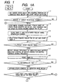
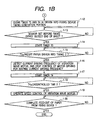
- Fig. 1 is comprised of Figs. 1A and 1B illustrating flow charts showing the function of a first embodiment of the present invention.
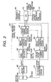
- Fig. 2 is a block diagram showing the control system of the first embodiment of the present invention;
- Fig. 3 is a chart showing the relationships between the load variation and the frequency and between the rotation torque and the drive frequency;
- Fig. 4 is a schematic view showing the configuration of an image forming apparatus constituting the first embodiment of the present invention;
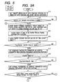
- Fig. 5 is comprised of Figs. 5A and 5B illustrating flow charts showing the function of a second embodiment;
- Fig. 6 is a block diagram showing the control system of the second embodiment;
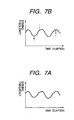
- Figs. 7A and 7B are charts showing the characteristics in function of the first and second embodiments; and
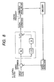
- Fig. 8 is a block diagram showing the PI control system of the second embodiment.
-
- Figs. 1A and 1B and Figs. 2 to 4 illustrate a first embodiment of the present invention.
- Fig. 4 schematically shows the entire configuration of a color image forming apparatus. At first there will be explained the configuration of a color reader unit.
- There are shown a
CCD 101; aboard 311 on which theCCD 101 is mounted; aprinter process unit 312; a glass plate (platen) 301 for supporting the original; an original feeding device 302 (which may by replaced by an unrepresented pressure plate of mirror surface or white color);light sources reflectors light sources mirrors 307 to 309; and alens 310 for condensing the reflected or projected light from the original onto theCCD 101. - There are also shown a
first carriage 314 housing thehalogen lamps reflectors mirror 307; asecond carriage 315 housing themirrors first carriage 314 is mechanically driven with a velocity V while thesecond carriage 315 is driven with a velocity V/2 in a direction perpendicular to the electrical scanning direction (main acanning direction) of theCCD 101 to scan (sub scan) the entire area of the original. - A printer unit shown in Fig. 4 is constructed as follows. There are provided a magenta (M)
image forming unit 317; a cyan (C)image forming unit 318; a yellow (Y)image forming unit 319; and a black (K)image forming unit 320. As these units are constructed in identical manner, there will be explained the Mimage forming unit 317 only in the following. - In the M
image forming unit 317, there are provided aphotosensitive drum 342 on which a latent image is formed by the light from anLED recording head 210; aprimary charger 321 for charging the surface of thephotosensitive drum 342 at a predetermined potential as a preparatory step for latent image formation; and a developingunit 322 for developing the latent image on thephotosensitive drum 342 thereby forming a toner image. The developingunit 322 includes asleeve 345 which receives a developing bias voltage for the development. - A
transfer charger 323 executes discharge from the rear side of a recordingsheet conveyor belt 333 thereby transferring the toner image from thephotosensitive drum 342 onto a recording sheet supported on theconveyor belt 333. In the present embodiment, there is not provided a cleaner unit for removing the toner remaining on the photosensitive drum after the image transfer because of the high image transfer efficiency, but such cleaner unit may naturally be provided without any inconvenience. - In the following there will be explained the sequence of transferring the toner image onto the recording material such as paper. The recording material such as recording paper, contained in a
cassette pickup roller feed rollers material conveyor belt 333. - The supplied recording sheet is charged by an
attraction charger 346. In the present embodiment, amongbelt rollers 348a to 348d for the recording sheet conveyor belt, theroller 348a is used as the driving roller for the conveyor belt and also for charging the recording sheet in cooperation with theattraction charger 346 thereby attracting the recording sheet to theconveyor belt 333. However any ofother belt rollers 348 may be used as the driving roller for driving theconveyor belt 333, or there may be provided a driving roller for driving theconveyor belt 333 at the other side (at the side of the fixing unit 334). - A sheet
front end sensor 347 serves to detect the front end of the recording sheet on theconveyor belt 333. The detection signal of the sheetfront end sensor 347 is supplied from the printer unit to the color reader unit and is utilized as the sub scan synchronization signal for the transmission of the video signal from the color reader unit to the printer unit. - Subsequently the recording sheet is transported by the
conveyor belt 333 and is subjected to the formation of toner images in theimage forming units 317 to 320 in the order of M, C, Y and K colors. After passing the Kimage forming unit 320, the recording sheet is subjected to charge elimination by acharge eliminator 349 in order to facilitate separation from theconveyor belt 333 and is separated therefrom. Aseparation charger 350 is provided for preventing the image perturbation resulting from the peeling discharge at the separation of the recording sheet from theconveyor belt 333. The separated recording sheet is charged bypre-fixing charges unit 334 and is discharged to asheet discharge tray 335. There is also provided asensor 353 for detecting the recording sheet. - In the present embodiment, vibration wave motors are employed for rotating the
photosensitive drums 342 to 345, and a vibration wave motor is also employed for rotating the driving roller for driving the recordingsheet conveyor belt 333. - As explained in the foregoing, the vibration wave motor utilizes plural vibrations excited in the vibration member with frequencies generally in the ultrasonic region, and the driving frequency, driving voltage or pulse width thereof is controlled according to the speed detection signal, detected by a speed sensor for detecting the motor driving speed, for achieving stable rotation at a constant speed.
- In the following there will be explained the features of the present embodiment with reference to Figs. 1A, 1B, 2 and 3.
- Figs. 1A and 1B are flow charts showing the functions featuring the present embodiment, while Fig. 2 is a block diagram of a drive control device for the vibration wave motor, and Fig. 3 is a chart showing the behavior of the driving pulses for the vibration wave motor in the control thereof.
- Referring to the flow charts shown in Figs. 1A and 1B, when an image forming operation is instructed from an
operation portion 300, there are activated the motors for driving the drum and the recording sheet conveyor belt and an unrepresented motor for sheet feeding from the cassette and for driving the fixing belt. In the following there will be explained the control sequence principally of the control device for the vibration wave motor. - A
control portion 404 shown in Fig. 2 executes speed control normally by driving frequency control according to the speed difference detected by aspeed difference detector 403, but, in periods of steps 1-7 to 1-10 and steps 1-16 to 1-19, the driving frequency control according to the speed difference is replaced by the drive control with the frequency employed immediately before the execution of the step 1-7 or 1-16. - In a step 1-1, a
CPU 412 sets a target speed value for the control portion of the vibration wave motor (in the present embodiment, the vibration wave motor for driving each photosensitive drum or for image transfer) to aspeed difference detector 403 of a drivingfrequency control portion 404. - The vibration wave motor USM (applying frequency signals to an electromechanical energy conversion elements such as piezoelectric elements provided on the vibration member to induce vibrations therein thereby obtaining a driving force) has a lower revolution with a higher driving frequency as shown in Fig. 3.
Therefore, in starting the vibration wave motor, the predetermined revolution is reached by gradually decreasing the frequency from a predetermined frequency. - The driving
frequency control portion 404 compares the signal from anencoder 402 with the target value, and decreases or increases the driving frequency respectively in case the speed detected at a drivingfrequency detecting portion 405 is lower or higher, so as that the output of the encoder coincides with (or comes close to) the target speed. - In a step 1-2, it is discriminated whether the target revolution has been reached, and, if reached, in a step 1-3, the image forming sequence is initialized. For this purpose the recording material such as paper is fed from a cassette (not shown but replaceable by other sheet feeding means), and a
sensor 352 positioned in front of thesheet feeding rollers rollers - Then, in a step 1-4, sheet feeding is executed, and a timer T1 for judging the timing of shock (instantaneous load variation) given by the recording sheet to the
conveyor belt 333 and a timer T2 for judging the timing control switching are cleared. Thus, as the sheet feeding operation and the image forming operation proceed according to predetermined schedules, it is possible to predict the time of arrival of the recording sheet at the conveyor belt. - In the configuration of the present embodiment, the variation in the load is assumed to be induced in the
conveyor belt 333 when the sheet is attracted there, but, in other configurations, there may be executed a similar process at the timing of such variation in the load. - In a step 1-5, it is started to drive the
sheet feeding rollers - In a step 1-6, it is determined that the value of the timer T1 reaches a preset paper feed-in or
arrival time 1 at which the load variation occurs and discriminates a timing immediately before the feeding-in or arrival of the paper, and in a step 1-7, the current driving frequency of the vibration wave motor before the shock is given to theconveyor belt 333 by the arrival of the paper is detected, the detected frequency is set in a controlmode switching portion 407 and the driving frequency supplied from the drivingfrequency detecting portion 405 is switched to thus set frequency for supply to a drivingfrequency generation porion 406. - Consequently, the driving pulses are outputted continuously at the set frequency. Therefore, even in case of an abrupt variation in the load, possibly exceeding the controlled range, the control does not diverge and the rotation continues substantially with the predetermined revolution. As this control is required only for a short period at the sheet arrival, in a step 1-8, the timer T2 is simultaneously started with the start of the above-mentioned control, in order to measure the
uncontrolled time 1. Theuncontrolled time 1 is the duration of the shock, and, when the lapse of theuncontrolled time 1 is discriminated in a step 1-9, the controlmode switching portion 407 switches, in a step 1-10, the mode to the control by the signal from the drivingfrequency detecting portion 405. - In case of a continuous image forming operation (for forming plural copies), the sequences proceed in parallel manner, so that the feeding of the next sheet is started from the step 1-3 while the sequence proceeds to a step 1-11.
- In a step 1-11, since the prededing sheet may not arrive into the image fixing device, the operation of the sequency is stopped until the
pre-fixing sensor 353 detects the entry of the preceding sheet into the fixing device. - As this step is not required for the first sheet, the sequence proceeds to a step 1-12.
- The timers T3, T4 of a fixing timing generation portion are cleared in a step 1-12, since the sequence starting from the step 1-12 is same as that of the aforementioned steps 1-4 to 1-10 and serves to avoid the shock caused by the sheet at the entry into the fixing device.
- In a step 1-13, it is discriminated whether the front end of the sheet has arrived at the
sensor 353 positioned in front of the fixing device. - When the front end of the sheet is detected, the timer T3 is started in a step 1-14. There is then measured a present paper feeding-in or
arrival time 2 defining the time required by the sheet front end to proceed from thepre-fix sensor 353 to the fed-in portion of the fixing device, and, before the entry of the sheet into the fixing device, the current driving frequency of the vibration wave motor is detected in a step 1-16. Then the detected frequency is set in the control mode switching portion, and the driving frequency is switched from the frequency given by the drivingfrequency detection porion 405 to thus set frequency and is given to the drivingfrequency generation portion 406. - Consequently, the driving pulses are outputted continuously at the set frequency. Therefore, even in case of an abrupt variation in the load, possibly exceeding the controlled range, the control does not diverge and the rotation continues substantially with the predetermined revolution. As this control is required only for a short period at the sheet arrival, the timer T4 is simultaneously started with the start of the above-mentioned control in a step 1-17, in order to measure the
uncontrolled time 2. - The
uncontrolled time 2 is the duration of the shock, and, when the lapse of theuncontrolled time 2 is discriminated in a step 1-18, the controlmode switching portion 407 switches, in a step 1-19, the mode to the control by the signal from the drivingfrequency detecting portion 405. - The discharge of the sheet from the fixing device is awaited in a step 1-20 and then an ending sequence, for example stopping the motors etc is executed.
- As the present embodiment employs five vibration wave motors, the block of the vibration wave motor, rotary encoder, driving
frequency control portion 404 and ACvoltage generation unit 411 shown in Fig. 2 is provided in five units. The vibration wave motor and the rotary encoder are connected coaxially, and the rotary encoder outputs a speed signal according to the rotation of the vibration wave motor. - The speed signal is compared with the target value in the
speed difference detector 403 to obtain the difference, and the obtained speed difference signal is used in the drivingfrequency detection portion 405 for determining the driving frequency so as to decrease or increase the driving frequency in case of increasing or decreasing the speed, and the detected driving frequency is supplied to the controlmode switching portion 407. - The control
mode switching portion 407 selects either the detected driving frequency or the frequency set by theCPU 412, and causes the drivingfrequency generating portion 406 to generate the driving frequency. Then the drivingpulse generation portion 410 generates pulses to be actually given to the vibration wave motor, and the pulses are power amplified by the ACvoltage generation portion 411 and are supplied to the vibration wave motor. - Figs. 5A, 5B and 6 illustrate a second embodiment, respectively showing flow charts and the control unit for the vibration wave motor.
- The present embodiment is to set, in the driving frequency detection portion, a parameter for restricting the response in control during the period in which the vibration wave motor is subjected to the instantaneous load increase, as will be explained in the following with reference to Fig. 8. The response in control is variable depending on the control method, and an example of the PI control is shown in Fig. 8. The control signal is represented by:
- If Gp and Gi increase with respect to the speed difference VD, the control signal increases, so that the response becomes faster by an increase in GP or Gi. The controlling parameter is different depending on the actual drive control system, but, in the present embodiment, Gi is changed so as to restrict the response. This is naturally limited to the present embodiment, and the restriction of response may naturally be achieved not only by the parameter GP, Gi but, in other control systems (for example a PID control or a combination thereof), by certain parameters to be multiplied with the deviation values.
- Now referring to the flow charts shown in Figs. 5A and 5B, at first there are activated the vibration wave motors for driving the plural photosensitive drums, that for driving the recording sheet conveyor belt and another unrepresented motor for sheet feeding from the cassette and for driving the fixing belt. In the following there will be explained the control sequence principally of the control device for the vibration wave motor.
- A
control portion 604 shown in Fig. 6 constantly executes driving frequency control according to the speed difference detected by aspeed difference detector 403, and, in periods of steps 5-7 to 5-10 and steps 5-16 to 5-19, the aforementioned driving frequency control with such control parameters as to restrict the response. - In a step 5-1, a
CPU 612 sets a target speed value for the control portion of the vibration wave motor (in the present embodiment, four vibration wave motors for driving the photosensitive drums, and the vibration wave motor for driving the recording sheet conveyor belt) to aspeed difference detector 403 of a drivingfrequency control portion 604. - The vibration wave motor USM has a lower revolution with a higher driving frequency as shown in Fig. 3. Therefore, in starting the vibration wave motor, the predetermined revolution is reached by gradually decreasing the frequency from a predetermined frequency.
- The
control portion 604 compares the signal from anencoder 402 with the target value, and decreases or increases the driving frequency respectively in case the speed detected at a drivingfrequency detecting portion 405 is lower or higher, so as that the output of the encoder coincides with (or comes close to) the target speed. - In a step 5-2 it is discriminated whether the target revolution has been reached, and, if reached, the image forming sequence is initialized in a step 5-3.
- For this purpose the recording paper is fed from a cassette (not shown but replaceable by other sheet feeding means), and a
sensor 352 positioned in front of thesheet feeding rollers rollers - Then sheet feeding is executed in a step 5-4, and a timer T1 for judging the timing of shock given by the recording sheet to the
conveyor belt 333 and a timer T2 for switching the control are cleared. - In the configuration of the present embodiment, the variation in the load is assumed to be induced in the
conveyor belt 333 when the sheet is attracted there, but, in other configurations, there may be executed a similar process at the timing of such variation in the load. - In a step 5-5 it is started to drive the
sheet feeding rollers - In a step 5-6, it is determined that the value of the timer T1 reaches a preset paper feed-in or
arrival time 1 at which the load variation occurs and discriminates a timing immediately before the feeding-in or arrival of the paper, and in a step 5-7, control parameters for the restricted response of the vibration wave motor is set in the drivingfrequency detection portion 605 before the shock is given to theconveyor belt 333 by the arrival of the paper. Therefore, even in case of an abrupt variation in the load, possibly exceeding the controlled range, the control does not diverge and the rotation continues substantially with the predetermined revolution. - At this control is required only for a short period at the sheet arrival, in a step 5-8, the timer T2 is simultaneously started with the start of the above-mentioned control, in order to measure the
limited time 1. Thelimited time 1 is the duration of the shock, and, when the lapse of thelimited time 1 is discriminated in a step 5-9, the control parameters of the drivingfrequency detection portion 605 is returned to the ordinary control parameters in a step 5-10. - In case of a continuous image forming operation (for forming plural copies), the sequences proceed in parallel manner, so that the feeding of the next sheet is started from the step 5-3 while the sequence proceeds to a step 5-11.
- In a step 5-11, since the preceding sheet may not arrive into the image fixing device, the operation of the sequence is stopped until the preceding sheet enters the fixing device.
- At this step is not required for the first sheet, the sequence proceeds to a step 5-12. The timers T3, T4 of a fixing timing generation portion are cleared in a step 5-12, since, the sequence starting from the step 5-12 is same as that of the aforementioned steps 5-4 to 5-10 and serves to avoid the shock caused by the sheet at the entry into the fixing device.
- In a step 5-13, it is discriminated whether the front end of the sheet has arrived at the
sensor 353 positioned in front of the fixing device. When the front end of the sheet is detected, the timer T3 is started in a step 5-14. There is then measured a presetpaper arrival time 2 defining the time required by the sheet front end to proceed from the pre-fix sensor to the arrival portion of the fixing device, and, before the entry of the sheet into the fixing device, the control parameters with restricted response is set in the drivingfrequency detection portion 605 in a step 5-16. - Therefore, even in case of an abrupt variation in the load, possibly exceeding the controlled range, the control does not diverge and the rotation continues substantially with the predetermined revolution.
- As this control is required only for a short period at the sheet arrival, the timer T4 is simultaneously started with the start of the above-mentioned control in a step 5-17, in order to measure the
limited time 2. Thelimited time 2 is the duration of the shock, and, when the lapse of thelimited time 2 is discriminated in a step 5-18, the control parameters of the drivingfrequency detection portion 605 is returned to the ordinary control parameters in a step 5-19. - The discharge of the sheet from the fixing device is awaited in a step 5-20 and then an ending sequence, for example stopping the motors etc is executed.
- As the present embodiment employs five vibration wave motors, the block of the vibration wave motor, rotary encoder, driving
frequency control portion 604 and ACvoltage generation unit 411 shown in Fig. 6 is provided in five units. The vibration wave motor and the rotary encoder are connected coaxially, and the rotary encoder outputs a speed signal according to the rotation of the vibration wave motor. The speed signal is compared with the target value in thespeed difference detector 403 to obtain the difference, and the obtained speed difference signal is used in the drivingfrequency detection portion 605 for determining the driving frequency according to the response parameters, so as to decrease or increase the driving frequency in case of increasing or decreasing the speed. - In the first and second embodiments explained in the foregoing, in case of an instantaneous excessive variation in the load as shown in Fig. 3, if the driving frequency is controlled with satisfactory response so as to improve the accuracy of rotation, the driving frequency shows an abrupt change, exceeding the ordinary controlled frequency range for the vibration wave motor and eventually leading to the stoppage of the motor.
- However such excessive variation in the load is mostly instantaneous, and, in the apparatus involving sheet feeding, the load generally increases instantaneously when the sheet enters or plunges into the driving system. By fixing the control of the vibration wave motor with the driving frequency prior to the instantaneous load variation, the characteristics in Fig. 3 change as shown in Fig. 7A whereby the stoppage of the vibration wave motor can be prevented.
- Otherwise the control gain is adjusted to restrict the response only during such instantaneous load variation, whereby the instantaneous response amount it reduced as shown in Fig. 7B, thereby decreasing the possibility of stoppage of the motor.
- Furthermore, the feedback control may also be achieved by a change in the driving voltage (duty ratio of the driving pulses) or the phase difference of the driving signals, instead of the driving frequency.
- Furthermore, it is possible to selectively execute these processes.
- Furthermore, it is possible to detect the variation in the load and to restrict the response during such variation.
Claims (12)
- A method of controlling the speed of a vibration wave motor (USM) by using a control device comprising:characterised in that the method comprises the steps of:drive state signal receiving means (403) for receiving a signal indicative of a drive state of the motor;drive frequency generation means (406) for generating a drive frequency for driving the motor;target drive state signal receiving means (403) for receiving a signal indicative of a target drive state for the motor;feedback control means (403, 405, 406) for varying the drive frequency generated by the drive frequency generation means so as to reduce a difference between the indicated drive state of the motor and the target drive state for the motor; andan operation control unit (407) for varying the operation of the feedback control means,receiving (1-3) a signal indicative of the timing of a motor load change; andon the basis of said received signal, using the operation control unit (407) to change the operation of the feedback control means from a time before the load change until after the load change by either i) inhibiting the feedback control means or by ii) changing a parameter of the feedback control means to reduce the variation of the frequency of the drive frequency signal in response to said difference between the detected drive state and the target drive state.
- A method according to claim 1, wherein the step of inhibiting the feedback control means causes the drive frequency generation means (406) to generate a predetermined drive frequency.
- A method according to claim 1, wherein the step of inhibiting the feedback control means causes the drive frequency generation means (406) to maintain the drive frequency at the drive frequency immediately before the inhibition.
- A method according to any one of claims 1 to 3, wherein after the step of changing, the feedback control means is operated under the changed condition for a predetermined period (T2).
- A method according to claim 4, wherein the step of changing the operation of the feedback control means occurs at the end of a predetermined period (T1) after receiving the signal indicative of the timing of a motor load change.
- A control device (404) for controlling a vibration wave motor (USM), comprising:characterised in that:drive state signal receiving means (403) for receiving a signal indicative of a drive state of the motor;drive frequency generation means (406) for generating a drive frequency for driving the motor;target drive state signal receiving means (403) for receiving a signal indicative of a target drive state for the motor;feedback control means (403, 405, 406) for varying the drive frequency generated by the drive frequency generation means so as to reduce a difference between the indicated drive state of the motor and the target drive state for the motor; andan operation control unit (407) for changing the operation of the feedback control means,the control device comprises motor load change timing signal receiving means (407) for receiving a signal indicative of the timing of a motor load change; andin that the operation control unit is operable to change the operation of the feedback control means, in response to a received motor load change timing signal, from a time before the load change until after the load change by either i) inhibiting the feedback control means or by ii) changing a parameter of the feedback control means to reduce the variation of the frequency of the drive frequency signal in response to said difference between the detected drive state and the target drive state.
- A control device according to claim 6, wherein the operation control unit (407) is operable to inhibit the feedback control means so that the drive frequency generation means (406) generates a predetermined drive frequency.
- A control device according to claim 4, wherein the operation control unit (407) is operable to inhibit the feedback control means so that the drive frequency generated by the drive frequency generation means (406) is maintained at the drive frequency immediately before the inhibition.
- A control device according to any one of claims 6 to 8, wherein said operation control unit (407) is operable to change the operation for a predetermined period (T2).
- A control device according to claim 9, wherein said operation control unit (407) is operable to change the operation at the time which occurs at the end of a predetermined period (T1) after receiving a motor load change timing signal.
- A vibration wave motor (USM) in combination with a control device according to any one of claims 6 to 10 operable to control the vibration wave motor.
- An image forming apparatus provided with a vibration wave motor (USM) and an image bearer member (342, 343, 344, 345) drivable by the motor, and having a control device according to any one of claims 6 to 10 for controlling the vibration wave motor (USM).
Applications Claiming Priority (2)
| Application Number | Priority Date | Filing Date | Title |
|---|---|---|---|
| JP18396498A JP4077934B2 (en) | 1998-06-30 | 1998-06-30 | Vibration wave motor drive control method, vibration wave motor drive control apparatus, apparatus including vibration wave motor, and image forming apparatus |
| JP18396498 | 1998-06-30 |
Publications (2)
| Publication Number | Publication Date |
|---|---|
| EP0969528A1 EP0969528A1 (en) | 2000-01-05 |
| EP0969528B1 true EP0969528B1 (en) | 2004-10-06 |
Family
ID=16144909
Family Applications (1)
| Application Number | Title | Priority Date | Filing Date |
|---|---|---|---|
| EP99305121A Expired - Lifetime EP0969528B1 (en) | 1998-06-30 | 1999-06-29 | Drive control for vibration wave motor |
Country Status (4)
| Country | Link |
|---|---|
| US (1) | US6285145B1 (en) |
| EP (1) | EP0969528B1 (en) |
| JP (1) | JP4077934B2 (en) |
| DE (1) | DE69920817T2 (en) |
Cited By (1)
| Publication number | Priority date | Publication date | Assignee | Title |
|---|---|---|---|---|
| CN106787939A (en) * | 2017-03-06 | 2017-05-31 | 北京卫星制造厂 | A kind of high accuracy drive control device of piezoelectric ceramic ultrasonic motor |
Families Citing this family (10)
| Publication number | Priority date | Publication date | Assignee | Title |
|---|---|---|---|---|
| JP2001272898A (en) * | 2000-03-28 | 2001-10-05 | Canon Inc | Image forming apparatus |
| JP4500408B2 (en) * | 2000-03-29 | 2010-07-14 | キヤノンプレシジョン株式会社 | Vibration wave motor drive control device, drive control method, and storage medium |
| JP2002095272A (en) * | 2000-09-11 | 2002-03-29 | Minolta Co Ltd | Driver |
| EP1324391B1 (en) * | 2001-12-24 | 2007-06-27 | Abb Research Ltd. | Module housing and power semiconductor module |
| JP2003309897A (en) * | 2002-04-17 | 2003-10-31 | Sanyo Electric Co Ltd | Circuit for controlling vibrator |
| JP4503417B2 (en) * | 2004-10-29 | 2010-07-14 | 株式会社リコー | Image forming apparatus |
| JP4735081B2 (en) * | 2005-06-30 | 2011-07-27 | ブラザー工業株式会社 | Motor control method, motor control device, and image forming apparatus |
| JP5387942B2 (en) * | 2008-09-01 | 2014-01-15 | 株式会社リコー | Transfer device and image forming apparatus |
| JP2013219871A (en) * | 2012-04-05 | 2013-10-24 | Canon Inc | Motor control device |
| JP2024036803A (en) * | 2022-09-06 | 2024-03-18 | キヤノン株式会社 | Vibration type actuator control device and its control method, drive device, and electronic equipment |
Family Cites Families (10)
| Publication number | Priority date | Publication date | Assignee | Title |
|---|---|---|---|---|
| JPS58148682A (en) | 1982-02-25 | 1983-09-03 | Toshio Sashita | Motor device using supersonic vibration |
| JPS59204477A (en) | 1983-05-04 | 1984-11-19 | Nippon Kogaku Kk <Nikon> | Surface wave motor utilizing supersonic wave vibration |
| JPS60176470A (en) | 1984-02-21 | 1985-09-10 | Canon Inc | Drive system of vibration wave motor |
| JPS631379A (en) | 1986-06-03 | 1988-01-06 | Toshio Sashita | Driving circuit for ultrasonic motor |
| US5159253A (en) | 1987-02-24 | 1992-10-27 | Canon Kabushiki Kaisha | Control device for a vibration wave motor |
| JP2537267B2 (en) | 1988-05-30 | 1996-09-25 | キヤノン株式会社 | Vibration type actuator device |
| JPH03239170A (en) | 1990-02-15 | 1991-10-24 | Brother Ind Ltd | Ultrasonic motor |
| JPH03256579A (en) | 1990-03-06 | 1991-11-15 | Brother Ind Ltd | Ultrasonic wave motor |
| JP2819437B2 (en) | 1990-12-17 | 1998-10-30 | アンリツ株式会社 | Ultrasonic motor drive controller |
| JP3674216B2 (en) * | 1997-02-25 | 2005-07-20 | 松下電工株式会社 | Drive control method for linear vibration motor |
-
1998
- 1998-06-30 JP JP18396498A patent/JP4077934B2/en not_active Expired - Fee Related
-
1999
- 1999-06-28 US US09/337,038 patent/US6285145B1/en not_active Expired - Lifetime
- 1999-06-29 DE DE69920817T patent/DE69920817T2/en not_active Expired - Lifetime
- 1999-06-29 EP EP99305121A patent/EP0969528B1/en not_active Expired - Lifetime
Cited By (2)
| Publication number | Priority date | Publication date | Assignee | Title |
|---|---|---|---|---|
| CN106787939A (en) * | 2017-03-06 | 2017-05-31 | 北京卫星制造厂 | A kind of high accuracy drive control device of piezoelectric ceramic ultrasonic motor |
| CN106787939B (en) * | 2017-03-06 | 2019-06-18 | 北京卫星制造厂 | A kind of high-precision drive control device of piezoelectric ceramic ultrasonic motor |
Also Published As
| Publication number | Publication date |
|---|---|
| DE69920817T2 (en) | 2006-03-09 |
| JP2000023476A (en) | 2000-01-21 |
| US6285145B1 (en) | 2001-09-04 |
| EP0969528A1 (en) | 2000-01-05 |
| JP4077934B2 (en) | 2008-04-23 |
| DE69920817D1 (en) | 2004-11-11 |
Similar Documents
| Publication | Publication Date | Title |
|---|---|---|
| KR101238140B1 (en) | Motor control apparatus and image forming apparatus | |
| US6084334A (en) | Driving apparatus for driving plurality of vibration type motors | |
| US6100622A (en) | Driving apparatus of vibration type actuator | |
| US8081905B2 (en) | Image forming apparatus and method of correcting rotation angular velocity of image bearing member | |
| US8899581B2 (en) | Image processing apparatus, rotation control method for motor, and computer-readable recording medium | |
| EP0969528B1 (en) | Drive control for vibration wave motor | |
| EP0924849B1 (en) | Motor control apparatus | |
| US6411008B1 (en) | Drive device for vibration type motor and image forming apparatus | |
| JP4544489B2 (en) | Image forming apparatus | |
| US6333609B1 (en) | Drive control device of vibration type motor | |
| JP3768664B2 (en) | Drive device for vibration type actuator, apparatus using vibration type actuator, and image forming apparatus | |
| JP2003153558A (en) | Oscillatory wave motor drive controller | |
| JP2000092874A (en) | Driving control for oscillatory wave motor, oscillatory wave motor, driving controller therefor, device therewith, and image forming device | |
| JPH11285292A (en) | Motor-control device and image-forming device | |
| JPH11178370A (en) | Vibration-type drive device and image-forming apparatus | |
| JP2000092873A (en) | Drive for oscillatory wave motor, device therewith, device therewith as driving source and image forming device | |
| JP2003153559A (en) | Oscillatory wave motor drive controller | |
| JP2000175470A (en) | Oscillatory wave driver and imaging apparatus | |
| JP2000184760A (en) | Driver for oscillatory motor and image forming device | |
| JP5751806B2 (en) | Motor drive device and image forming apparatus | |
| JP2003153564A (en) | Image forming device | |
| JPH11136975A (en) | Equipment having vibration type drive apparatus, image forming apparatus and vibration type actuator | |
| JP2003037984A (en) | Vibration wave motor drive control device, drive voltage control method, program and storage medium | |
| JPH09325556A (en) | Image forming device, method therefor and storage medium storing the method | |
| JPH11191989A (en) | Motor control method and device and image-forming device |
Legal Events
| Date | Code | Title | Description |
|---|---|---|---|
| PUAI | Public reference made under article 153(3) epc to a published international application that has entered the european phase |
Free format text: ORIGINAL CODE: 0009012 |
|
| AK | Designated contracting states |
Kind code of ref document: A1 Designated state(s): DE FR GB IT |
|
| AX | Request for extension of the european patent |
Free format text: AL;LT;LV;MK;RO;SI |
|
| 17P | Request for examination filed |
Effective date: 20000522 |
|
| AKX | Designation fees paid |
Free format text: DE FR GB IT |
|
| 17Q | First examination report despatched |
Effective date: 20020731 |
|
| GRAP | Despatch of communication of intention to grant a patent |
Free format text: ORIGINAL CODE: EPIDOSNIGR1 |
|
| GRAS | Grant fee paid |
Free format text: ORIGINAL CODE: EPIDOSNIGR3 |
|
| GRAA | (expected) grant |
Free format text: ORIGINAL CODE: 0009210 |
|
| AK | Designated contracting states |
Kind code of ref document: B1 Designated state(s): DE FR GB IT |
|
| PG25 | Lapsed in a contracting state [announced via postgrant information from national office to epo] |
Ref country code: IT Free format text: LAPSE BECAUSE OF FAILURE TO SUBMIT A TRANSLATION OF THE DESCRIPTION OR TO PAY THE FEE WITHIN THE PRESCRIBED TIME-LIMIT;WARNING: LAPSES OF ITALIAN PATENTS WITH EFFECTIVE DATE BEFORE 2007 MAY HAVE OCCURRED AT ANY TIME BEFORE 2007. THE CORRECT EFFECTIVE DATE MAY BE DIFFERENT FROM THE ONE RECORDED. Effective date: 20041006 |
|
| REG | Reference to a national code |
Ref country code: GB Ref legal event code: FG4D |
|
| REF | Corresponds to: |
Ref document number: 69920817 Country of ref document: DE Date of ref document: 20041111 Kind code of ref document: P |
|
| ET | Fr: translation filed | ||
| PLBE | No opposition filed within time limit |
Free format text: ORIGINAL CODE: 0009261 |
|
| STAA | Information on the status of an ep patent application or granted ep patent |
Free format text: STATUS: NO OPPOSITION FILED WITHIN TIME LIMIT |
|
| 26N | No opposition filed |
Effective date: 20050707 |
|
| PGFP | Annual fee paid to national office [announced via postgrant information from national office to epo] |
Ref country code: FR Payment date: 20120712 Year of fee payment: 14 |
|
| REG | Reference to a national code |
Ref country code: FR Ref legal event code: ST Effective date: 20140228 |
|
| PG25 | Lapsed in a contracting state [announced via postgrant information from national office to epo] |
Ref country code: FR Free format text: LAPSE BECAUSE OF NON-PAYMENT OF DUE FEES Effective date: 20130701 |
|
| PGFP | Annual fee paid to national office [announced via postgrant information from national office to epo] |
Ref country code: GB Payment date: 20150626 Year of fee payment: 17 Ref country code: DE Payment date: 20150630 Year of fee payment: 17 |
|
| REG | Reference to a national code |
Ref country code: DE Ref legal event code: R119 Ref document number: 69920817 Country of ref document: DE |
|
| GBPC | Gb: european patent ceased through non-payment of renewal fee |
Effective date: 20160629 |
|
| PG25 | Lapsed in a contracting state [announced via postgrant information from national office to epo] |
Ref country code: DE Free format text: LAPSE BECAUSE OF NON-PAYMENT OF DUE FEES Effective date: 20170103 |
|
| PG25 | Lapsed in a contracting state [announced via postgrant information from national office to epo] |
Ref country code: GB Free format text: LAPSE BECAUSE OF NON-PAYMENT OF DUE FEES Effective date: 20160629 |