EP0969417A2 - Verfahren und Vorrichtung zur dreidimensionalen Anzeige mittels eines Tensorwiedergabe - Google Patents
Verfahren und Vorrichtung zur dreidimensionalen Anzeige mittels eines Tensorwiedergabe Download PDFInfo
- Publication number
- EP0969417A2 EP0969417A2 EP99305197A EP99305197A EP0969417A2 EP 0969417 A2 EP0969417 A2 EP 0969417A2 EP 99305197 A EP99305197 A EP 99305197A EP 99305197 A EP99305197 A EP 99305197A EP 0969417 A2 EP0969417 A2 EP 0969417A2
- Authority
- EP
- European Patent Office
- Prior art keywords
- tensor
- light
- dimensional
- rendering
- data
- Prior art date
- Legal status (The legal status is an assumption and is not a legal conclusion. Google has not performed a legal analysis and makes no representation as to the accuracy of the status listed.)
- Withdrawn
Links
Images

Classifications
-
- G—PHYSICS
- G06—COMPUTING OR CALCULATING; COUNTING
- G06T—IMAGE DATA PROCESSING OR GENERATION, IN GENERAL
- G06T15/00—3D [Three Dimensional] image rendering
Definitions
- the present invention relates to a display of general three-dimensional digital data and more particularly, to a method and apparatus for displaying multi-valued component data by use of tensor rendering, which can be used, e.g., for applications which follow.
- the scalars of three-dimensional lattice points are given to calculate coordinate data including the apexes, ridge lines and face orientations of polygons of isosurface in a three-dimensional space, and resultant polyhedron data are hidden-surface-processed for display.
- a radiative transfer equation is approximately solved to represent the concentration of a spatial density without determining the surfaces of a three-dimensional figure.
- This method which represents a shape as a degree of opacity is featured in that since the operation of determining an isosurface involves no data round-down based on a threshold, the quality of input data reflects on the quality of a display image as it is.
- this method uses only a radiation-transportation model of a scattering light for relating a single function to opacity or color and uses no such a scattering light model as able to cope with multi-valued component data of a multi-value function. For this reason, for displaying the multi-valued component data, the method requires not only the repetition of volume-rendering-calculation for each of the multi-valued component data, demanding a massive amount of calculation, but also a post-processing for comparison of an image to be displayed.
- Another prior art method for displaying multi-valued component data of a multi-value function is a method for displaying a three-dimensional icon (see IEEE Visualization 93, pp.39-45) as an image.
- a distribution of three-dimensional multi-valued component data is displayed by displaying as an image the situation in which a three-dimensional icon object having a freedom of shape corresponding to the multi-valued component data is positioned in a space.
- a limited resolution of display screen disables simultaneous display of a multiplicity of sampling points.
- the multi-valued component data to be displayed are selected, undesirably leading to display of only part of the data to be analyzed.
- Another prior art method for displaying multi-valued component data of a multi-value function is a method for simultaneously displaying five three-dimensional components (see IEEE Visualization 97, pp.479-482). In this method, not tensors but two types of scalars and one type of vector are overwritten, and an geometrical object is utilized. Thus, this method is limited to applications where it is desired to display a small number of sampling points.
- a method for displaying three-dimensional tensor components (see IEEE Visualization 97, pp.59-66).
- features are extracted from a distribution of nine components of a three dimensional tensor amount to three-dimensionally display its extracted result.
- This method is suitable for such a purpose as to display the features of a multi-value function.
- this metod cannot be used for such a purpose as to detect fine defects from the entire multi-valued component data, because most of the data are subjected to the selecting operations prior to displaying.
- the present invention may be applied to an internal structure diagnosis apparatus using a magnetic resonance imaging (MRI) system for a sample having a spin component.
- MRI magnetic resonance imaging
- the conventional method for displaying a three-dimensional icon as an image has a limit in resolution, because the method is of a geometrical figure display type based on sample extraction and cannot display all the data. Further, with respect to display, a polygon indicative of an icon has to be displayed in color and cannot be visualized on a monochrome display screen. Moreover, since shading is used regardless of display information, multi-valued components having a large value change range cannot be undesirably displayed.
- the present invention has five objects that provide a method and apparatus for displaying high-dimensional (e.g., three-dimensional) digital data by use of tensor rendering which has the following functions and effects (1) to (5).
- An ordinary computer system which comprises a data processing system including a multi-value function data input part, a data processing part and an image data output display part, and also comprising a user interface for input of instructions for necessary parameter control.
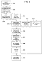
- the data processing is realized in accordance with a flowchart shown in Fig. 2.
- a high dimensional multi-value function is input (block 201).
- the luminance of the reflection light is specified on the basis of an opacity according to a path length of light traversed through the anisotropic ellipsoid.
- the input based on the anisotropic ellipsoid is of a non-geometrical data type.
- the opacity and the scattering light vector as the light reflection direction are controlled directly by the discrete sample region unit 103 having three-dimensional two-order tensor amount.
- Tensor type multi-valued component data of the input multi-value function are sorted into symmetrical tensor components and anti-symmetrical tensor components (or by decomposing the input data, if the sorting is impossible) (block 202).
- Such an input method is employed as to map the tensor type multi-valued components as shape coefficients ( ⁇ and ⁇ in Equation 2) of the anisotropic ellipsoid (block 203), that is, by relating the tensor components to the shape, i.e., axial length of the anisotropic ellipsoid. This causes the determination of the opacity and orientation corresponding to the input components.
- the anisotropic ellipsoid is used to determine the scattering (reflecting) intensity of the light (block 207), and corresponds to non-geometrical data. As a result, a geometrical object as the ellipsoid is not displayed.
- Equation 1 examples of velocity-stress tensor (Equation 1) in fluid mechanics often used in engineering include a stress tensor (Equation 3) as a symmetrical tensor, an anti-symmetrical tensor (Equation 4) such as vorticity, and so forth.
- a scattering light model can be used which is based on an orthorhombic crystal (Equation 7) calculated from the auxiliary functions of Equations 8 to 11.
- vectors N, V, V', H, H' and T in Equation 6 for definition of inner or scalar product indicate a normal-direction vector 104, a light-source-directed vector 105, a line of sight vector 106, a bisector-direction vector 107, a tangential-direction vector 108 and an in-plane anisotropic axis vector 109 in Fig. 1, respectively.
- the scattering light due to three sets of three-dimensional vectors and so forth can be used.
- the mapping input as the shape coefficients of the anisotropic ellipsoid in the block 203 causes the distribution function at a lattice position specified as a discrete point in the three-dimensional space in a block 204 to be calculated (block 205).
- an ellipsoid intersection of the light source position specified in a block 211 and the sight line set in a block 212 is calculated (block 206).
- light beam integration calculation (block 208) executed by weighting the anisotropic ellipsoid is suitable for the parallel calculation, because the integration can be dividedly carried out for each light beam.
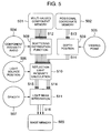
- the exemplary arrangement of the present invention includes storage memories (501 to 503) for holding input/output data therein, interfaces (504 to 507) through which control parameters are input, operating parts (508 to 511), and data (512 to 516) being transmitted through a data communication system such as a network.
- an anisotropic scattering contribution ratio is set as a parameter on the basis of a component 504 and an anisotropic scattering ratio at each data sampling point is calculated in the scattering distribution function calculation part 508 according to the scattering distribution function.
- the three-dimensional coordinate data 513 read out from the positional coordinate memory 502 holding the spatial position coordinate values of the sampling point therein is subjected in a depth position calculation part 509 to a three-dimensional coordinate converting operation according to a sight line position set by a viewing-point setting device 505 to generate converted coordinate values and the list vectors 514 in an order of the viewing depth direction.
- the light beam integration calculation part 511 integrates the quantities of permeated light in the viewing depth order corresponding to the generation order of the list vectors 514 according to an opacity set by the opacity setting device 507. Its integrated results become three primary color signals of color brightness in a two-dimensional image, and are written in the output image memory 503 as the image data 516.
- the image data read out from the output image memory 503 are converted and output to a display output device (not shown) such as a CRT motor, a liquid crystal monitor or a color printer.
- a display output device such as a CRT motor, a liquid crystal monitor or a color printer.
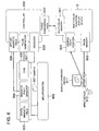
- FIG. 6 shows an apparatus which displays a distribution of three-dimensional structure defects in an image obtained from the MRI apparatus based on an ordinary computer system.
- the display apparatus will be explained with reference to Fig. 6.
- an MRI apparatus 602 holding a test sample 601 includes a uniform static magnetic field generator 603, a magnetic field gradient generator 604 and a coil 605 for reception and transmission of an electromagnetic signal.
- a application-magnetic-field controller 606 for controlling the intensity or gradient of a magnetic field to be applied, generates a magnetic field gradient 604 to create such a magnetic field environment as to be able to measure a spin echo.
- a pulse generator 607 connected to the coil 605 acts to apply an exciting magnetic field generated by the coil 605.
- An electromagnetic signal indicative of a spin echo from the sample is received by the coil 605 and sent to a receiver 608 where the signal is converted.
- the received spin echo signal is reconstructed into three-dimensional multi-component data 610 in a controller 609 which performs the correlation processing between the received spin echo signal and the applied pulse signal.
- the three-dimensional multi-component data 610 is applied to a multi-value function display device 5 to be stored in the multi-valued component memory 501.
- a rendering result of the three-dimensional multi-valued components is output to the image memory 503 as two-dimensional image data.
- Data output from the image memory 503 is sent to a display diagnosis device 611 such as a CRT monitor, and then converted.
- the observer using an input device 612 such as a mouse, interactively or automatically operates the three-dimensional display parameters, e.g. moves a viewing point position 505. Through the operations including the viewing-point movement, the information observer can diagnostically find an abnormality in the three-dimensional distribution by visually recognizing the abnormality in the brightness characteristic caused by the effect of the anisotropic scattering light on the display diagnosis device 611.
- the defect position can also be identified.
- the present invention has the following effects (1) to (6).
Landscapes
- Engineering & Computer Science (AREA)
- Computer Graphics (AREA)
- Physics & Mathematics (AREA)
- General Physics & Mathematics (AREA)
- Theoretical Computer Science (AREA)
- Image Generation (AREA)
- Magnetic Resonance Imaging Apparatus (AREA)
- Image Processing (AREA)
- Image Analysis (AREA)
Applications Claiming Priority (2)
| Application Number | Priority Date | Filing Date | Title |
|---|---|---|---|
| JP20283498 | 1998-07-03 | ||
| JP10202834A JP2000020745A (ja) | 1998-07-03 | 1998-07-03 | テンソルレンダリングによる三次元デジタルデータの表示方法及び装置 |
Publications (2)
| Publication Number | Publication Date |
|---|---|
| EP0969417A2 true EP0969417A2 (de) | 2000-01-05 |
| EP0969417A3 EP0969417A3 (de) | 2003-01-02 |
Family
ID=16463972
Family Applications (1)
| Application Number | Title | Priority Date | Filing Date |
|---|---|---|---|
| EP99305197A Withdrawn EP0969417A3 (de) | 1998-07-03 | 1999-07-01 | Verfahren und Vorrichtung zur dreidimensionalen Anzeige mittels eines Tensorwiedergabe |
Country Status (3)
| Country | Link |
|---|---|
| US (1) | US6441821B1 (de) |
| EP (1) | EP0969417A3 (de) |
| JP (1) | JP2000020745A (de) |
Cited By (1)
| Publication number | Priority date | Publication date | Assignee | Title |
|---|---|---|---|---|
| CN1307548C (zh) * | 2002-03-21 | 2007-03-28 | 微软公司 | 用于低频照明环境的光自转移的图形图像演示方法和系统 |
Families Citing this family (18)
| Publication number | Priority date | Publication date | Assignee | Title |
|---|---|---|---|---|
| US6845342B1 (en) * | 1999-05-21 | 2005-01-18 | The United States Of America As Represented By The Department Of Health And Human Services | Determination of an empirical statistical distribution of the diffusion tensor in MRI |
| JP4393016B2 (ja) * | 2000-06-30 | 2010-01-06 | 株式会社日立メディコ | 画像診断支援装置 |
| US6573893B1 (en) * | 2000-11-01 | 2003-06-03 | Hewlett-Packard Development Company, L.P. | Voxel transfer circuit for accelerated volume rendering of a graphics image |
| WO2002063569A1 (en) * | 2001-02-09 | 2002-08-15 | Koninklijke Philips Electronics N.V. | Method for volume rendering |
| JP4554834B2 (ja) * | 2001-02-21 | 2010-09-29 | 任天堂株式会社 | 画像処理装置及び方法並びにそのプログラム |
| JP2005514683A (ja) * | 2001-12-06 | 2005-05-19 | ニューヨーク・ユニバーシティ | 合成、認識および圧縮のための多モード・データ集団の多重線形表現のための論理装置、データ構造、システムおよび方法 |
| US7355597B2 (en) * | 2002-05-06 | 2008-04-08 | Brown University Research Foundation | Method, apparatus and computer program product for the interactive rendering of multivalued volume data with layered complementary values |
| EP1709572A2 (de) * | 2004-01-13 | 2006-10-11 | New York University | Verfahren, system, speichermedium und datenstruktur zur bilderkennung unter verwendung einer multilinearen unabhängigen komponentenanalyse |
| JP2007066055A (ja) * | 2005-08-31 | 2007-03-15 | Ritsumeikan | 3次元オブジェクト内で3次元的に分布するテンソル量を表示するコンピュータプログラム及びテンソル量表示画像データ生成方法 |
| US7583262B2 (en) * | 2006-08-01 | 2009-09-01 | Thomas Yeh | Optimization of time-critical software components for real-time interactive applications |
| US7602180B2 (en) * | 2006-11-02 | 2009-10-13 | Siemens Aktiengesellschaft | System and method for fast texture-based tensor field visualization for DT-MRI |
| US7936906B2 (en) * | 2007-06-15 | 2011-05-03 | Microsoft Corporation | Face recognition using discriminatively trained orthogonal tensor projections |
| US8024152B2 (en) * | 2008-09-23 | 2011-09-20 | Microsoft Corporation | Tensor linear laplacian discrimination for feature extraction |
| JP5929902B2 (ja) * | 2011-04-05 | 2016-06-08 | 日本電気株式会社 | 情報処理装置 |
| CN103914871B (zh) * | 2014-03-06 | 2016-06-08 | 河南农业大学 | 基于点云数据的交互式选取物体表面坐标点的方法 |
| DE102016213926B4 (de) * | 2016-07-28 | 2018-10-31 | Siemens Healthcare Gmbh | Verfahren zur Bestimmung eines Diffusionstensors mittels eines Magnetresonanztomographen und Vorrichtung |
| WO2020069121A1 (en) * | 2018-09-26 | 2020-04-02 | Northwestern University | Space-time scattering network for inverse design and tomography |
| CN114928492B (zh) * | 2022-05-20 | 2023-11-24 | 北京天融信网络安全技术有限公司 | 高级持续威胁攻击识别方法、装置和设备 |
Family Cites Families (2)
| Publication number | Priority date | Publication date | Assignee | Title |
|---|---|---|---|---|
| JP3555039B2 (ja) | 1993-07-07 | 2004-08-18 | 株式会社ソキア | アブソリュート・エンコーダ |
| AU7554894A (en) * | 1993-08-06 | 1995-02-28 | Government Of The United States Of America, As Represented By The Secretary Of The Department Of Health And Human Services, The | Method and system for measuring the diffusion tensor and for diffusion tension imaging |
-
1998
- 1998-07-03 JP JP10202834A patent/JP2000020745A/ja active Pending
-
1999
- 1999-07-01 EP EP99305197A patent/EP0969417A3/de not_active Withdrawn
- 1999-07-06 US US09/347,419 patent/US6441821B1/en not_active Expired - Fee Related
Cited By (1)
| Publication number | Priority date | Publication date | Assignee | Title |
|---|---|---|---|---|
| CN1307548C (zh) * | 2002-03-21 | 2007-03-28 | 微软公司 | 用于低频照明环境的光自转移的图形图像演示方法和系统 |
Also Published As
| Publication number | Publication date |
|---|---|
| JP2000020745A (ja) | 2000-01-21 |
| US6441821B1 (en) | 2002-08-27 |
| EP0969417A3 (de) | 2003-01-02 |
Similar Documents
| Publication | Publication Date | Title |
|---|---|---|
| US6441821B1 (en) | Method and apparatus for displaying three-dimensional image by use of tensor rendering | |
| EP0915434B1 (de) | System zur Flächendarstellung mit volumetrischen Abstandskarten | |
| EP2477159B1 (de) | System und Verfahren zum Echtzeit-Co-Rendering mehrerer Attribute | |
| CA1285660C (en) | Method and system for solid modelling | |
| CA2806197A1 (en) | Obtaining data from an earth model using functional descriptors | |
| EP1347418A2 (de) | Texturabbildungseditierung | |
| US6573893B1 (en) | Voxel transfer circuit for accelerated volume rendering of a graphics image | |
| MXPA06001497A (es) | Sistema y metodo para aplicar texturas tridimensionales de volumen exacto a superficies arbitrariamente trianguladas. | |
| EP0967578A2 (de) | Objektwiedergabesystem zur Erzeugung röntgenähnlicher Bilder | |
| Bürger et al. | Visualization of multi-variate scientific data. | |
| Reed et al. | Coupling rendering and generative adversarial networks for artificial SAS image generation | |
| EP1024460A2 (de) | Graphische Objekten mit Oberflächeelementen dargestellt | |
| Samaras et al. | Incorporating illumination constraints in deformable models | |
| US6967653B2 (en) | Apparatus and method for semi-automatic classification of volume data | |
| Benger et al. | Tensor splats | |
| Scheuermann et al. | Visualizing planar vector fields with normal component using line integral convolution | |
| Huitema et al. | Interactive visualization of protein dynamics | |
| Wood | Visualization and modeling of 3-D structures (medical imaging) | |
| Hlawitschka et al. | Fast and memory efficient gpu-based rendering of tensor data | |
| CN115546429A (zh) | 一种光栅化管道的前视成像声呐与双目相机联合仿真方法 | |
| Schoor et al. | VR based visualization and exploration of plant biological data | |
| Schiavone et al. | Interoperability issues for terrain databases in distributed interactive simulation | |
| EP0549183A2 (de) | System zur Anzeige von räumlichen Einschnitten für Festkörpermodellflächen | |
| Schafhitzel et al. | Interactive investigation and visualization of 3d vortex structures | |
| Padmanaba et al. | A software environment for autocovariance based motion analysis |
Legal Events
| Date | Code | Title | Description |
|---|---|---|---|
| PUAI | Public reference made under article 153(3) epc to a published international application that has entered the european phase |
Free format text: ORIGINAL CODE: 0009012 |
|
| AK | Designated contracting states |
Kind code of ref document: A2 Designated state(s): AT BE CH CY DE DK ES FI FR GB GR IE IT LI LU MC NL PT SE |
|
| AX | Request for extension of the european patent |
Free format text: AL;LT;LV;MK;RO;SI |
|
| PUAL | Search report despatched |
Free format text: ORIGINAL CODE: 0009013 |
|
| AK | Designated contracting states |
Kind code of ref document: A3 Designated state(s): AT BE CH CY DE DK ES FI FR GB GR IE IT LI LU MC NL PT SE |
|
| AX | Request for extension of the european patent |
Free format text: AL;LT;LV;MK;RO;SI |
|
| 17P | Request for examination filed |
Effective date: 20030605 |
|
| AKX | Designation fees paid |
Designated state(s): DE FR GB |
|
| 17Q | First examination report despatched |
Effective date: 20040217 |
|
| STAA | Information on the status of an ep patent application or granted ep patent |
Free format text: STATUS: THE APPLICATION IS DEEMED TO BE WITHDRAWN |
|
| 18D | Application deemed to be withdrawn |
Effective date: 20040629 |