EP0969412A2 - Vector data compression - Google Patents
Vector data compression Download PDFInfo
- Publication number
- EP0969412A2 EP0969412A2 EP99304630A EP99304630A EP0969412A2 EP 0969412 A2 EP0969412 A2 EP 0969412A2 EP 99304630 A EP99304630 A EP 99304630A EP 99304630 A EP99304630 A EP 99304630A EP 0969412 A2 EP0969412 A2 EP 0969412A2
- Authority
- EP
- European Patent Office
- Prior art keywords
- codeword
- hvq
- compression
- compressor
- pixel
- Prior art date
- Legal status (The legal status is an assumption and is not a legal conclusion. Google has not performed a legal analysis and makes no representation as to the accuracy of the status listed.)
- Granted
Links
Images

Classifications
-
- G—PHYSICS
- G06—COMPUTING OR CALCULATING; COUNTING
- G06T—IMAGE DATA PROCESSING OR GENERATION, IN GENERAL
- G06T9/00—Image coding
- G06T9/008—Vector quantisation
Definitions
- HVQ hierarchical vector quantization
- the table is set up so that if an exact match of the input pixel bits is not available, then a codeword associated with the closest match is output instead.
- the ultimate output of this stage 1 is four codewords, each describing the closest match to the bit pattern of the two input pixels. Since the exact match frequently is not possible, this compression is inherently lossy to some extent.
- the output of the first stage is four 9-bit codewords.
- each codeword is simply applied to a 256 K by 64 bit LUT which outputs the bit pattern of the entire 8-pixel block.
- Printing hints are sometimes generated in a printing system at the scanner or text generator to indicate to various printing elements the type of data that is being received. The system will then be able to optimize its compression elements for the data.
- a problem is that the hints are supplied on data lines separate from the data, which complicates the system.
- the hints are incorporated in the data stream, there would be a problem of separating them out, and also the data compression ratio would suffer if the hints were included in the output data.
- HVQ hierarchical vector quantization
- a method of compressing a series of data words comprises compressing several data words into a codeword using hierarchical vector quantization (HVQ) and then using a lossless pattern matching compressor to compress the codeword string and is characterised by adding a printing hint to the end of a codeword before the codeword is applied to the lossless compressor.
- HVQ hierarchical vector quantization
- This invention solves the problem by using lossy and lossless compressors in series.
- the lossy compressor compresses the data and then adds the hint to the data, which makes the data output longer.
- an LZ compressor which looks for previously used data patterns. To the extent that the current and previous data patterns have the same hint, which is almost always the case, then the length of the pattern does not matter, and the compression ratio will not be affected significantly.
- a compressor using HVQ is used for the lossy stage.
- the compressor not only receives printing hints which are used to determine which compression process to use, but also includes the printing hints in the compressed output for use by subsequent printing stages; the inclusion not materially affecting the compression ratio through the use of a lossy and a lossless compression stage in series.
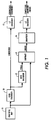
- the basic HVQ system can be improved by adding an error channel as shown in Figure 1.
- the grayscale byte map 16 is applied in the usual way to an HVQ decoder 10, the output is losslessly compressed in an LZ encoder 11, and the result is sent to the decoder, usually in the form of 8 to 10-bit words.
- the output of the HVQ encoder is sent to a decoder 12 in scanline format which produces a version of the original byte map which may be different from the original because of errors possibly introduced by the lossy encoder.
- the two byte maps are then subtracted 13, pixel by pixel, to produce error terms which, if added to the output codeword, will produce the original byte map.
- This subtraction can also be done by using an exclusive OR, which is simpler and faster and does not require a sign bit.
- These error terms, each a signed quantity 8-bits wide or less, can then be compressed in an LZ encoder 15 and sent to the decoder in parallel with the original output. The larger the error term, the less will be the compression ratio. In practice, small errors are not visually detectable.
- the error term can be limited to a few most significant bits, three for example, in quantizer 14. Normally, the amount of error for a pixel will not be large enough to show up in the few MSB's, in which case there will be no error term at all.
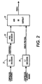
- the quantized error decoder is shown in Figure 2.
- the compressed code words are LZ decoded in decoder 21 and HVQ decoded in decoder 22 to produce one term for the adder 23.
- the compressed quantized errors are LZ decoded in decoder 24 and applied as the other term to the adder 23, the output of which is output video.
- the adder 23 can either be an adder adding a sign bit and seven bits, or an exclusive OR if one was used to generate the error term in the encoder.
- Figure 3 shows the arrangement when a single code word 31 is split into most and least significant parts, 32, 33, and where only the least significant bits are compressed.
- bits 0 through 4 are sent through lossy compressor 35 while bits 5 through 7 are not. Both are then compressed using lossless LZ compression and output to the decoder shown in Figure 4.
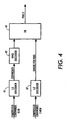
- both channels are LZ decompressed while only the LSB's are HVQ decoded.
- the two resultant parts are then exclusive ORed 44 together to be applied to the decoding look up table.
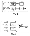
- Figure 5 is a system where a single pixel is separated into a least significant segment and a most significant segment, and where a separate and different compression process is used for each segment, the least significant bits being more compressed.
- the original pixel is separated into its most significant bits 52 and least significant bits 53. The result is that the most significant bits, being the most important, are less compressed while compression for the least significant bits has a better compression ratio.
- a programmable look-up table could be used to split the input pixel into any two segments other than the 3 - 5 split shown.
- Figure 6 is the decoder for the encoder of Figure 5.
- the two compressed outputs of Figure 5 are applied to LZ decoders 61, 62 and HVQ 63, 64 decoded. Then both are applied to an exclusive OR gate 65 to assemble the entire pixel.
- LZ decoders 61, 62 and HVQ 63, 64 decoded.
- both are applied to an exclusive OR gate 65 to assemble the entire pixel.
- the encoder used some other combination of encoders, the decoder would use the same form of decoding. That is, more generally, the data words in a string can be divided into more and less significant bits to create two parallel strings, and then compressed using any two methods of compression where the greater compression is applied to less significant bits.
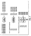
- HVQ compression is easily adapted to image rotation and mirror imaging as shown in Figure 7.
- the process is shown here using the example of an original image that is four pixels high and sixteen pixels wide, and must be rotated ninety degrees clockwise and mirror imaged.
- Step 1 is the usual compression process of reducing the eight 8-pixel segments to eight codewords Cw1 to Cw8.
- Step 2 is the step of rearranging the codewords into the rotated and mirror imaged order.
- This hardware can be in the form of wiring where the second word in, for example Cw2, is connected to the third word out, as shown.
- Step 2 can have several sets of wiring, each set delivering a different rotation.
- decoding step 3 uses a look-up table to produce a pixel pattern for each segment that is properly oriented. Here again, several tables can be used to produce various orientations.
- Printing hints may be incorporated into the original data supplied by the user in the original page description language to indicate to the printer how the data may best be printed.
- a hint word may be two bits in length, and indicate one of four possibilities, that the following data is text, contone, graphics, etc. For example, if the printer is receiving data that originated as a computer generated graphic it may use a different halftone screen than it would if the original data was screened in from a photograph.
- Printing hints may be added to any HVQ channel as shown in Figure 5. Assume that for each 4 pixel block entering into the HVQ encoder 54 there is produced one codeword 9 bits in length, contained in two 8-bit bytes, so that the first 8 bits are contained in the first byte and the last bit is contained in the second byte. Then the 2-bit hint is added. Now, each codeword plus hint is 11 bits, still contained in two bytes. The LZ encoder looks at a string of bytes, perhaps 256 bytes in length, and determines the location and size of the most recent identical pattern match. To the extent that the hint changes once or twice within that string, there will be a slightly decreased amount of compression in comparison to the amount that would have resulted with no hints.
- the losses of an HVQ compressor can be further minimized by choosing codewords and output data patterns that have the best chance of matching the actual input data patterns. For example, first consider text. If text pixels are being encoded in 4 by 2 pixel groups, and the four input pixels in one line are black, dark gray, light gray and white, and the input video was scanned-in text, the data most likely originally was a boundary between a black letter and a white space, so the output pixel pattern could be black, black, white, white. On the other hand, if the original input data was a scanned-in computer generated graphic, the four pixels are more likely to be a smooth decrease in density from black to white. The actual determination of the encoder codewords and patterns in the decoder look-up table are determined by statistical analysis. A representative group of text and graphic documents are passed through a test program and the best values are generated for each type.
- a complication arises when a boundary passes through an input block of pixels, in which case neither text nor graphic values can be used for the entire block.
- the solution is to supply a third set of codewords and patterns which are generated specifically for this boundary condition.
- a set of documents containing both text and graphics would be analyzed to produce one set of patterns, which would be used when a boundary, mixed, condition is determined to be within the block.
- the boundary condition is sensed by observing the printing hints.
- a rectangular scanned-in picture is typically located on a page of text by its x,y coordinates.
- the printing hints will indicate to the printer which codewords, look-up table entries and halftone screens to use. If the hint changes from picture to text within the block, for example, then the encoder knows that a boundary exists within the block.
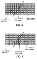
- Figure 8 is an example of a transition between text and contone. Since different block sizes can be used in HVQ encoders for different kinds of data, the block size for the text is shown here as 2 by 2 pixels to allow greater edge detail while the block size for contone is shown as being 4 by 2 to allow for greater compression.
- a boundary is within a 2 by 2 pixel block, that block is encoded and decoded using boundary values.
- any contone pixels to the right of the boundary such as pixel 81 are also treated as a boundary pixels if necessary so that all remaining pixels to the right of the boundary line will be within 4 by 2 pixel blocks.
- 2 by 2 pixel boundary blocks are used in pairs so that all remaining blocks will be 4 by 2.
Landscapes
- Engineering & Computer Science (AREA)
- Multimedia (AREA)
- Physics & Mathematics (AREA)
- General Physics & Mathematics (AREA)
- Theoretical Computer Science (AREA)
- Compression Of Band Width Or Redundancy In Fax (AREA)
- Compression, Expansion, Code Conversion, And Decoders (AREA)
- Compression Or Coding Systems Of Tv Signals (AREA)
Abstract
Description
Claims (2)
- A compressor of the type which compresses a series of data words by compressing several data words into a codeword using hierarchical vector quantization (HVQ) and then using a lossless pattern matching compressor to compress the codeword string, the compressor including means for adding a printing hint to the end of a codeword before the codeword is applied to the lossless compressor.
- A method of compressing a series of data words comprising compressing several data words into a codeword using hierarchical vector quantization (HVQ) and then using a lossless pattern matching compressor to compress the codeword string characterised by adding a printing hint to the end of a codeword before the codeword is applied to the lossless compressor.
Applications Claiming Priority (2)
| Application Number | Priority Date | Filing Date | Title |
|---|---|---|---|
| US09/106,734 US6078696A (en) | 1998-06-29 | 1998-06-29 | HVQ compression of data and printing hints |
| US106734 | 1998-06-29 |
Publications (3)
| Publication Number | Publication Date |
|---|---|
| EP0969412A2 true EP0969412A2 (en) | 2000-01-05 |
| EP0969412A3 EP0969412A3 (en) | 2001-01-10 |
| EP0969412B1 EP0969412B1 (en) | 2004-05-19 |
Family
ID=22312972
Family Applications (1)
| Application Number | Title | Priority Date | Filing Date |
|---|---|---|---|
| EP99304630A Expired - Lifetime EP0969412B1 (en) | 1998-06-29 | 1999-06-15 | Vector data compression |
Country Status (4)
| Country | Link |
|---|---|
| US (1) | US6078696A (en) |
| EP (1) | EP0969412B1 (en) |
| JP (1) | JP2000078021A (en) |
| DE (1) | DE69917380T2 (en) |
Cited By (2)
| Publication number | Priority date | Publication date | Assignee | Title |
|---|---|---|---|---|
| US7349135B2 (en) * | 1998-12-18 | 2008-03-25 | Xerox Corporation | Time multiplexed image data decompression circuit |
| US7965406B2 (en) | 2002-10-25 | 2011-06-21 | Xerox Corporation | Time multiplexed image data decompression circuit |
Families Citing this family (6)
| Publication number | Priority date | Publication date | Assignee | Title |
|---|---|---|---|---|
| US6470052B1 (en) * | 1998-06-29 | 2002-10-22 | Xerox Corporation | HVQ compression combined with orthogonal rotation |
| DE69934939T2 (en) | 1998-06-29 | 2007-10-18 | Xerox Corp. | Compression of boundaries between images |
| US6307977B1 (en) * | 1998-11-17 | 2001-10-23 | Xerox Corporation | Set of run-length codewords containing printing hints |
| KR100579587B1 (en) * | 2003-06-30 | 2006-05-15 | 주식회사 대우일렉트로닉스 | Holographic playback data compression device and method |
| US7123174B1 (en) * | 2005-06-29 | 2006-10-17 | Xerox Corporation | Image compression and decompression using adaptive run length encoding |
| JP4434155B2 (en) * | 2006-02-08 | 2010-03-17 | ソニー株式会社 | Encoding method, encoding program, and encoding apparatus |
Family Cites Families (3)
| Publication number | Priority date | Publication date | Assignee | Title |
|---|---|---|---|---|
| US5583656A (en) * | 1992-12-31 | 1996-12-10 | Eastman Kodak Company | Methods and apparatus for attaching compressed look-up table (LUT) representations of N to M-dimensional transforms to image data and for processing image data utilizing the attached compressed LUTs |
| US5602589A (en) * | 1994-08-19 | 1997-02-11 | Xerox Corporation | Video image compression using weighted wavelet hierarchical vector quantization |
| US5999710A (en) * | 1997-06-17 | 1999-12-07 | Hewlett-Packard Company | Merge plane generation for a data processing pipeline |
-
1998
- 1998-06-29 US US09/106,734 patent/US6078696A/en not_active Expired - Lifetime
-
1999
- 1999-06-15 EP EP99304630A patent/EP0969412B1/en not_active Expired - Lifetime
- 1999-06-15 DE DE69917380T patent/DE69917380T2/en not_active Expired - Fee Related
- 1999-06-25 JP JP11180857A patent/JP2000078021A/en not_active Withdrawn
Cited By (2)
| Publication number | Priority date | Publication date | Assignee | Title |
|---|---|---|---|---|
| US7349135B2 (en) * | 1998-12-18 | 2008-03-25 | Xerox Corporation | Time multiplexed image data decompression circuit |
| US7965406B2 (en) | 2002-10-25 | 2011-06-21 | Xerox Corporation | Time multiplexed image data decompression circuit |
Also Published As
| Publication number | Publication date |
|---|---|
| DE69917380D1 (en) | 2004-06-24 |
| EP0969412B1 (en) | 2004-05-19 |
| DE69917380T2 (en) | 2004-10-14 |
| JP2000078021A (en) | 2000-03-14 |
| US6078696A (en) | 2000-06-20 |
| EP0969412A3 (en) | 2001-01-10 |
Similar Documents
| Publication | Publication Date | Title |
|---|---|---|
| EP0969656B1 (en) | Compression for image boundaries | |
| EP0969670B1 (en) | Unequal compression of MSBs and LSBs using Hierarchical Vector Quantization (HVQ) | |
| EP1285399B1 (en) | Enhanced compression of gray-level images | |
| US7903873B2 (en) | Textual image coding | |
| CN101375313B (en) | Compression of images for computer graphics | |
| US7415154B2 (en) | Compression of palettized color images with variable length color codes | |
| CN1266843C (en) | Coding method and system and decoding method and system | |
| CN101653004A (en) | Decoder for selectively decoding predetermined data units from an encoded bitstream | |
| EP0969412B1 (en) | Vector data compression | |
| EP0973339A2 (en) | Compression by splitting each word and applying lossy compression to least significant bits | |
| US6470052B1 (en) | HVQ compression combined with orthogonal rotation | |
| US6996269B2 (en) | Image encoding apparatus and image decoding apparatus | |
| EP0973340A2 (en) | HVQ compression with an error term | |
| JP2618944B2 (en) | Coding method of color image information | |
| US7292732B2 (en) | Image compression/decompression apparatus and method | |
| JP2925047B2 (en) | Data compression device and data decompression device | |
| JP3375080B2 (en) | Image compression method | |
| JP3375079B2 (en) | Image compression device | |
| JP3376831B2 (en) | Image compression method | |
| JPH07162689A (en) | Picture encoding device | |
| IL151741A (en) | Enhanced compression of gray level images | |
| JPH11242738A (en) | Method device for compressing and expanding picture, method/device for extending picture and storage medium |
Legal Events
| Date | Code | Title | Description |
|---|---|---|---|
| PUAI | Public reference made under article 153(3) epc to a published international application that has entered the european phase |
Free format text: ORIGINAL CODE: 0009012 |
|
| AK | Designated contracting states |
Kind code of ref document: A2 Designated state(s): DE FR GB |
|
| AX | Request for extension of the european patent |
Free format text: AL;LT;LV;MK;RO;SI |
|
| PUAL | Search report despatched |
Free format text: ORIGINAL CODE: 0009013 |
|
| AK | Designated contracting states |
Kind code of ref document: A3 Designated state(s): AT BE CH CY DE DK ES FI FR GB GR IE IT LI LU MC NL PT SE |
|
| AX | Request for extension of the european patent |
Free format text: AL;LT;LV;MK;RO;SI |
|
| 17P | Request for examination filed |
Effective date: 20010710 |
|
| AKX | Designation fees paid |
Free format text: DE FR GB |
|
| GRAP | Despatch of communication of intention to grant a patent |
Free format text: ORIGINAL CODE: EPIDOSNIGR1 |
|
| GRAS | Grant fee paid |
Free format text: ORIGINAL CODE: EPIDOSNIGR3 |
|
| GRAA | (expected) grant |
Free format text: ORIGINAL CODE: 0009210 |
|
| AK | Designated contracting states |
Kind code of ref document: B1 Designated state(s): DE FR GB |
|
| REG | Reference to a national code |
Ref country code: GB Ref legal event code: FG4D |
|
| REF | Corresponds to: |
Ref document number: 69917380 Country of ref document: DE Date of ref document: 20040624 Kind code of ref document: P |
|
| ET | Fr: translation filed | ||
| PLBE | No opposition filed within time limit |
Free format text: ORIGINAL CODE: 0009261 |
|
| STAA | Information on the status of an ep patent application or granted ep patent |
Free format text: STATUS: NO OPPOSITION FILED WITHIN TIME LIMIT |
|
| 26N | No opposition filed |
Effective date: 20050222 |
|
| PGFP | Annual fee paid to national office [announced via postgrant information from national office to epo] |
Ref country code: FR Payment date: 20050608 Year of fee payment: 7 |
|
| PGFP | Annual fee paid to national office [announced via postgrant information from national office to epo] |
Ref country code: DE Payment date: 20050609 Year of fee payment: 7 |
|
| PGFP | Annual fee paid to national office [announced via postgrant information from national office to epo] |
Ref country code: GB Payment date: 20050615 Year of fee payment: 7 |
|
| PG25 | Lapsed in a contracting state [announced via postgrant information from national office to epo] |
Ref country code: GB Free format text: LAPSE BECAUSE OF NON-PAYMENT OF DUE FEES Effective date: 20060615 |
|
| PG25 | Lapsed in a contracting state [announced via postgrant information from national office to epo] |
Ref country code: DE Free format text: LAPSE BECAUSE OF NON-PAYMENT OF DUE FEES Effective date: 20070103 |
|
| GBPC | Gb: european patent ceased through non-payment of renewal fee |
Effective date: 20060615 |
|
| REG | Reference to a national code |
Ref country code: FR Ref legal event code: ST Effective date: 20070228 |
|
| PG25 | Lapsed in a contracting state [announced via postgrant information from national office to epo] |
Ref country code: FR Free format text: LAPSE BECAUSE OF NON-PAYMENT OF DUE FEES Effective date: 20060630 |