EP0969346A2 - Überwachungssystem gegen Manipulation für Computer - Google Patents
Überwachungssystem gegen Manipulation für Computer Download PDFInfo
- Publication number
- EP0969346A2 EP0969346A2 EP99304992A EP99304992A EP0969346A2 EP 0969346 A2 EP0969346 A2 EP 0969346A2 EP 99304992 A EP99304992 A EP 99304992A EP 99304992 A EP99304992 A EP 99304992A EP 0969346 A2 EP0969346 A2 EP 0969346A2
- Authority
- EP
- European Patent Office
- Prior art keywords
- tamper
- rtc
- event
- signal
- tamper event
- Prior art date
- Legal status (The legal status is an assumption and is not a legal conclusion. Google has not performed a legal analysis and makes no representation as to the accuracy of the status listed.)
- Granted
Links
Images


Classifications
-
- H—ELECTRICITY
- H04—ELECTRIC COMMUNICATION TECHNIQUE
- H04L—TRANSMISSION OF DIGITAL INFORMATION, e.g. TELEGRAPHIC COMMUNICATION
- H04L63/00—Network architectures or network communication protocols for network security
- H04L63/10—Network architectures or network communication protocols for network security for controlling access to devices or network resources
-
- G—PHYSICS
- G06—COMPUTING OR CALCULATING; COUNTING
- G06F—ELECTRIC DIGITAL DATA PROCESSING
- G06F21/00—Security arrangements for protecting computers, components thereof, programs or data against unauthorised activity
- G06F21/70—Protecting specific internal or peripheral components, in which the protection of a component leads to protection of the entire computer
- G06F21/86—Secure or tamper-resistant housings
-
- G—PHYSICS
- G06—COMPUTING OR CALCULATING; COUNTING
- G06F—ELECTRIC DIGITAL DATA PROCESSING
- G06F21/00—Security arrangements for protecting computers, components thereof, programs or data against unauthorised activity
- G06F21/70—Protecting specific internal or peripheral components, in which the protection of a component leads to protection of the entire computer
- G06F21/88—Detecting or preventing theft or loss
-
- H—ELECTRICITY
- H04—ELECTRIC COMMUNICATION TECHNIQUE
- H04L—TRANSMISSION OF DIGITAL INFORMATION, e.g. TELEGRAPHIC COMMUNICATION
- H04L43/00—Arrangements for monitoring or testing data switching networks
-
- G—PHYSICS
- G06—COMPUTING OR CALCULATING; COUNTING
- G06F—ELECTRIC DIGITAL DATA PROCESSING
- G06F2211/00—Indexing scheme relating to details of data-processing equipment not covered by groups G06F3/00 - G06F13/00
- G06F2211/005—Network, LAN, Remote Access, Distributed System
-
- G—PHYSICS
- G06—COMPUTING OR CALCULATING; COUNTING
- G06F—ELECTRIC DIGITAL DATA PROCESSING
- G06F2221/00—Indexing scheme relating to security arrangements for protecting computers, components thereof, programs or data against unauthorised activity
- G06F2221/21—Indexing scheme relating to G06F21/00 and subgroups addressing additional information or applications relating to security arrangements for protecting computers, components thereof, programs or data against unauthorised activity
- G06F2221/2101—Auditing as a secondary aspect
-
- G—PHYSICS
- G06—COMPUTING OR CALCULATING; COUNTING
- G06F—ELECTRIC DIGITAL DATA PROCESSING
- G06F2221/00—Indexing scheme relating to security arrangements for protecting computers, components thereof, programs or data against unauthorised activity
- G06F2221/21—Indexing scheme relating to G06F21/00 and subgroups addressing additional information or applications relating to security arrangements for protecting computers, components thereof, programs or data against unauthorised activity
- G06F2221/2151—Time stamp
-
- H—ELECTRICITY
- H04—ELECTRIC COMMUNICATION TECHNIQUE
- H04L—TRANSMISSION OF DIGITAL INFORMATION, e.g. TELEGRAPHIC COMMUNICATION
- H04L2463/00—Additional details relating to network architectures or network communication protocols for network security covered by H04L63/00
- H04L2463/121—Timestamp
-
- H—ELECTRICITY
- H04—ELECTRIC COMMUNICATION TECHNIQUE
- H04L—TRANSMISSION OF DIGITAL INFORMATION, e.g. TELEGRAPHIC COMMUNICATION
- H04L43/00—Arrangements for monitoring or testing data switching networks
- H04L43/10—Active monitoring, e.g. heartbeat, ping or trace-route
- H04L43/106—Active monitoring, e.g. heartbeat, ping or trace-route using time related information in packets, e.g. by adding timestamps
Definitions
- the present invention relates to computer systems (including portable computer systems) and more particularly, to protecting such computer systems from theft or misuse.
- Personal computer systems are well known in the art. Personal computer systems have attained widespread use for providing computer power to many segments of today's modern society. Personal computers can typically be defined as a desktop, floor standing, or portable microcomputer. Examples of such personal computer systems are IBM's PC series and IBM's Thinkpad Series.
- EAS Electronic Article Surveillance
- EAS is an excellent technology for retail applications, however it is less effective for protecting assets of a corporation. Employees may have opportunities to defeat the technology such as removing the tags, passing components out though a mail service, or reusing parts within the building.
- U.S. patent application serial number 08/965,140 entitled “A Computer System for Sending An Alert Signal Over a Network When A Cover of Said System Has Been Opened" and assigned to the assignee of the present invention discloses a mechanism to notify a system administrator within a network (typically an Ethernet network) when the cover of the computer system is removed through the use of a timestamp. When the cover is removed, an Ethernet subsystem sends a cover tamper signal to the network administrator.
- the disadvantage to this method is that the timestamp is based on administrator receiving the alert. Given the lossy nature of an Ethernet network the packet may never be received by the system administrator. Another problem is the potential delays inherent in the network, which results in being unable to pin-point the time of the event with accuracy.
- U.S. Patent 5,388,156 discloses a personal computer system having security features enabling control over access to data retained in such a system.
- the personal computer system has a normally closed enclosure and at least one erasable memory element for receiving and storing a privileged access password (PAP).
- PAP is designed to provide protection for the system owner by protecting the initial program load (IPL) device boot list by access to a password utility.
- the system further includes at least one tamper detection switch mounted within the enclosure and operatively connected with the memory element for detecting opening of the enclosure.
- the tamper detection switch will change states and set the tamper evident bit. If this occurs, the system will require the PAP to be entered before the user can enter access data. If the PAP is not known, then the system board must be replaced. However, the system of the '156 patent has a disadvantage in that the time in which the cover was removed is not recorded.
- the invention provides a system for monitoring tamper events in a computer system on a network, the system comprising:
- the tamper event signal may represent a cover tamper signal, or a radio frequency tamper signal.
- the receiving means further includes a system real-time clock (RTC) including a nonvolatile memory for retaining the tamper event, and an adapter means coupled to the generating means for providing tamper event information to the network.
- the adapter means comprises a LAN adapter, the LAN adapter including a media access controller providing an interface between a shared data path and a local bus;
- the tamper real time clock (RTC) is coupled to a system bus for receiving at least one tamper event signal and latching the at least one tamper signal based upon a tamper event, the tamper RTC including means for retaining the time of the tamper event;
- management device is coupled between the local bus and a system bus within the computer system for receiving the at least one tamper event signal and for sending an alert packet to the LAN adapter means based upon the at least one tamper event, the alert packet including the time of the tamper event, the alert packet being obtained by
- the receiving means comprises: at least one receiver means for receiving a tamper event signal; a latch means for receiving at least one latch signal and being stopped by the at least one latch signal; a real time clock for receiving a signal from the timer means; and an interface means for allowing the issuing means to gain access to the real time clock.
- the invention provides a system for monitoring tamper events in a computer system, the computer system being on a network; the system comprising:
- the approach described herein provides a mechanism to accurately record the time when security breaches are detected.
- the mechanism works in conjunction with tamper detection mechanisms that are standard in many personal computer systems.
- the mechanism is software and configuration independent, to protect against a thief disabling or altering the event.
- the time of event is recorded in a secure fashion.
- a system for monitoring tamper events in a computer system on a network comprises a tamper realtime clock (RTC) means which receives at least one tamper event signal from the computer system.
- the tamper RTC includes a timer for indicating the time of a tamper event and a management device for receiving the at least one tamper event signal.
- the management device issues a command to the tamper RTC means to obtain the time of the at least one tamper event.
- the management device also generates a network packet which includes the time of the tamper event to a system administrator of the network.
- the computer system has the ability to functionally detect and store the time of a tamper event.
- a tamper real time clock (RTC) circuit is operatively connected with logic to store the date and time of an event as it occurs.
- the tamper event may be as simple as a toggle switch being activated when a cover on the computer system is removed.
- the computer system also sends network alerts when the cover is removed.
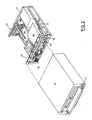
- a computer system generally indicated at 10 ( Figure 1) may have an associated display monitor 11, keyboard 12, mouse 14, and printer or plotter (not shown).
- the computer 10 is connected to a network by cable 36, which is connected to a hub 34.
- the network could be of type Ethernet, Token Ring, ATM, or other mechanism used to transmit data.
- the computer 10 has a cover 15 which is a decorative outer member which cooperates with a chassis 19 in defining an enclosed, shielded volume for receiving electrically powered data processing and storage components for processing and storing digital data. At least certain of these components are mounted on a multi layer planar 20 or motherboard which is mounted on the chassis 19 and provides a means for electrically interconnecting the components of the computer 10 including those identified above and such other associated elements as floppy disk drives, various forms of direct access storage devices, accessory adapter cards or boards, and the like. As pointed out more fully hereinafter, provisions are made in the planar 20 for the passage of input/output signals to and from the operating components of the microcomputer.
- the system 10 has a power supply 17, a power button 21, also herein referred to as switch 21.
- the chassis 19 defines a pair of upper bays 26, 28 and a lower bay 29.
- One of the upper bays 26 is adapted to receive peripheral drives of a first size (such as those known as 3.5 inch drives) while the other 28 is adapted to receive drives of a different size (such as a CD ROM drive) and the lower bay is adapted to receive another drive.
- One floppy disk drive is indicated at 27 in Figures 1 and 2, and is a removable medium direct access storage device (DASD) capable of receiving a diskette inserted there into and using the diskette to receive, store and deliver data as is generally known.
- DASD removable medium direct access storage device
- One CD ROM drive is indicated at 30 in Figures 1 and 2 and is a removable medium direct access storage device capable of receiving a compact disc inserted there into and using the disc to deliver data as is generally known.
- One hard disk drive is indicated at 31 in Figure 2 and is a fixed medium direct access storage device capable of storing and delivering data as is generally known.
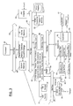
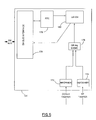
- FIG. 3 there is shown a block diagram of personal computer system 10, including components mounted on the planar 20 and the connection of the planar 20 to the IO expansion connectors and other hardware of the personal computer system.
- the system CPU or processor 40 Connected to the planar 20 is the system CPU or processor 40, which is connected directly to a high speed CPU host bus 42.
- a first system core logic chipset 44 and L2 cache memory 46 are also connected to the host bus 42.
- the first core logic chipset 44 includes a memory control unit, a L2 cache controller and a peripheral component interconnect (PCI) bridge.
- the memory control unit is further connected to a volatile random access memory (RAM) 48.
- the RAM memory 48 is composed of one or more memory modules.
- the memory controller includes the logic for mapping addresses to and from the microprocessor 40 to particular areas of RAM 48.
- the cache controller is operatively coupled to the L2 cache memory 46.
- the first core chipset 44 can be, for example, a Triton VX chip which is sold by Intel Corporation.
- the PCI bridge within chipset 44 provides an interface between the local bus 42 and a PCI bus 50.
- a second core chipset 52 and a plurality of PCI expansion connectors 54 for receiving PCI bus compatible peripheral cards.
- One such peripheral card is a video controller 56.
- the video controller 56 includes video memory and is coupled to the monitor or video display terminal 11.
- the chipset 52 can be, for example, a PIIX4 chip which is also sold by Intel Corporation.
- the chipset 52 contains a bus control and timing unit, a plurality of timers, an interrupt controller, a direct access memory (DMA) unit, nonvolatile CMOS RAM, also herein referred to as NVRAM, a CMOS real-time clock (RTC), a System Management (SM) bus controller, a PCI/ISA bridge, flash memory interface, power management logic and an integrated drive electronics (IDE) controller.
- the PCI/ISA bridge provides an interface between the PCI bus 50 and an optional feature or expansion bus such as the Industry Standard Architecture (ISA) bus 58. Connected to the ISA bus 58 are a plurality of ISA expansion connectors 60 for receiving ISA adapter cards (not shown).
- the IDE controller provides for the attachment of IDE compatible storage devices such as the fixed disk drive 31 and CD-ROM drive 30.
- the system real-time clock is used for time of day calculations and the NVRAM is used to store system configuration data. That is, the NVRAM will contain values which describe the present configuration of the system 10.
- NVRAM 52 contains information describing the type of fixed disk or diskette, the list of IPL devices set by a user and the sequence to be used for a particular power on method, the type of display, the amount of memory, time, date, etc.
- these data are stored in NVRAM whenever a special configuration program, such as configuration/setup, is executed.
- the purpose of the configuration/setup program is to store values characterizing the configuration of the system to NVRAM.
- Attached to core 52 is a flash memory (FM) module or chip 66.
- FM flash memory
- Power management circuitry 52 is for changing the system 10 between various power states (e.g., off, standby, sleep, suspend and normal operating states). Note that the particular power state of the computer is not directly relevant to the present invention (which is applicable to all such states), and accordingly, the description that follows will be independent of power state.
- IO controller 68 is Coupled to the ISA bus 58 such as, for example, a National Semiconductor PC87307.
- the IO controller 68 contains a variety of IO adapters and other components such as the diskette adapter 70, serial adapter 72, a parallel adapter 74 and keyboard controller 76.
- the diskette adapter 70 provides the interface to the diskette drive 27.
- the serial adapter 72 has an external port connector 82 for attachment of external devices such as a modem (not shown).
- the parallel adapter 74 has an external port connector 80 for attachment of external devices such as printers (not shown).
- the keyboard controller 76 is the interface for the keyboard 12 and the mouse 14.
- a LAN adapter or subsystem 94 can be coupled to either the PCI bus 50 or the ISA bus 58 for allowing system 10 to communicate with a LAN via a connection or link 36 to hub 34 (Fig. 1).
- the LAN adapter is supplied with auxiliary power (AUX5) from the power supply 17 when the system 10 is off.
- the LAN adapter can be, for example, an IBM Auto ALERT-ON LAN token ring adapter.
- a planar SM Bus 64 is coupled to the PCI bus 50 and ISA bus 58 via chipset 52.
- the planar SM Bus 64 is an additional IO bus in system 10 and is used as a local bus to support slow speed peripheral devices that reside on the planar board.
- Logic 92 which will be described later is coupled to SM bus 64.
- RFID (Radio Frequency Identification) EEPROM 90 is also coupled to the SM Bus 64 and an RF interface.
- the RFID EEPROM 90 is a dual ported non-volatile memory element with both a digital serial (I2C) and Radio Frequency interface.
- the non-volatile EEPROM includes asset information such as serial numbers and code revision for the system.
- the RFID EEPROM can be updated through a digital interface that connects to the SM bus 64 or through the RF interface which connects to antenna 120.
- system processor 40 could be an Intel Pentium processor, Cyrix 586-P75 processor or Advanced Micro Devices 586 processor or any other suitable microprocessor.
- microcomputer system 10 is shown with 16 megabytes of system memory 48, but additional memory can be interconnected as represented in Figure 3 by installing additional or higher-density memory modules.
- additional memory can be interconnected as represented in Figure 3 by installing additional or higher-density memory modules.
- FIG. 1 there is shown the local computer system 10 along with a perspective view of some form of LAN attachment through hub 34, in which effective communication may be established through electrically conductive connections, through fiber optical links, through infrared or other radiation links, or in other manners. Such a link is indicated in Figure 1 at 36.
- the network may be a token-ring network or an Ethernet network, or other known type of network.
- Each of the computers may be a "personal computer" as defined herein.
- the remote computer on the LAN may be some computer having capabilities other than those ascribed herein to a "personal computer", and possibly beyond those capabilities. While the term “remote” is used with reference to the computer system through which the LAN station local computer system 10 accesses BIOS, that term is used in the sense of indicating separation, rather than in the sense of indicating a large physical distance between the systems. In fact, such system may be physically adjacent in some network arrangements.
- a computer system in accordance with the present invention has the ability to functionally detect and record the time of a tamper event.
- the triggering events are tamper events detected by the computer system.
- the tamper event may be as simple as a toggle switch being activated when the cover of the personal computer is removed.
- the computer system of the preferred embodiment includes a tamper detection switch mounted within the enclosure and operatively connected with a logic unit to retain the time of the tamper event.
- the computer system is coupled to a remote computer via a data communication link and sends network alerts when the cover is removed.
- a management tamper real time clock (RTC) is operatively connected with logic to obtain and send the time of the event as part of the network alert.
- RFID Radio Frequency Identification
- tamper events are operatively connected to logic that contains a duplicate of the system's RTC.
- This duplicate RTC herein referred to as a tamper RTC contains a shadow of the system RTC but can be stopped by a tamper event.
- the hardware real time clock is powered by system battery to eliminate requirement on AC power being present.
- the tamper RTC is setup by Power On Self Test (POST) or a network administrator to ensure synchronization with the system RTC. Security of the timer setup is limited by requiring a user to enter a Privilege Access Password (PAP) to gain access.
- PAP Privilege Access Password
- POST When the system is powered on, POST checks to ensure the various tamper indicators are clear. If a tamper has occurred, it then prompts the user for a PAP. The system will not continue to boot or enter setup until the PAP is entered. If POST checks the duplicate RTC and no events have occurred it check synchronization of the system RTC and duplicate RTC. POST is designed to either correct the duplicate RTC or provide an error code depending on the network. The approach described herein provides for recording the date and time of the tamper event within the system such that security personnel can focus their investigation most effectively.
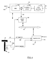
- FIG. 4 is a simplified block diagram of a system 90 including a LAN adapter 94.
- the LAN adapter 94 includes a Media Access Controller (MAC) 100.
- the MAC 100 serves as an interface between a shared data path (e.g., media independent interface (MII) (described below) and a PCI bus 50 or ISA bus 58.
- MII media independent interface
- the MAC 100 performs a number of functions involved in the transmission and reception of data packets. For example, during the transmission of data, the MAC 100 assembles the data to be transmitted into a packet with address and error detection fields. Conversely, during the reception of a packet, the MAC 100 disassembles the packet and performs address checking and error detection.
- the MAC 100 typically performs encoding/decoding of digital signals transmitted over the shared path and performs preamble generation/removal as well as bit transmission/reception.
- the MAC 100 can be for example, an Intel 82557 chip.
- the LAN adapter 94 further includes a media independent interface (MII) which is a local bus between the MAC 100 and a physical layer 102.
- MII media independent interface
- the physical layer 102 in a preferred embodiment implements a fully compliant IEEE 802.3u MII for connection to MACs.
- IEEE 802.3u MII is a specification of signals and protocols which formalizes the interfacing of a 10/100 Mbps Ethernet Media Access Controller to the underlying physical layer 102.
- the physical layer 102 in a preferred embodiment can be a fully integrated device supporting 10 and 100 Mb/s CSMA/CD Ethernet applications.
- the physical layer 102 receives parallel data from the MII local bus and converts it to serial data for transmission over cable 36.
- the physical layer 102 is also responsible for wave shaping and provides analog voltages to cable 36.
- the physical layer 102 can be for example, an Integrated Services Systems 1890 chip.
- the physical layer 102 also in a preferred embodiment includes auto-negotiation logic which has three main purposes. The first purpose is to determine the capabilities of the hub 34. A second purpose is to advertise its own capabilities to the remote computer 34. Finally, a third purpose of the physical layer 102 is to establish a connection with the remote computer 34 using the highest performance common connection technology.
- a management application specific integrated circuit (ASIC) 160 is coupled between the MII bus 63 and the SM bus 64.
- the management ASIC 160 includes a MII interface 1602 for receiving and sending data from a RX FIFO 1604 and TX FIFO 1606.
- the FIFO controller 1608 in turn is coupled to a microcontroller 1610 and NVRAM storage 1612.
- the NVRAM storage 1612 includes the packet header information.
- the management ASIC 160 also includes a SM interface 1614 which receives data from the SM bus 64. The functionality of the management ASIC 160 will be described in more detail later in the specification.
- a tamper real time clock (RTC) circuit 140 is also provided which communicates with the management ASIC 160 via the SM bus 64.
- the tamper RTC 140 is also coupled to a battery 142 to keep power on the tamper RTC even if the computer loses power.
- the tamper RTC circuit 140 also receives tamper event signals.
- the tamper events are a cover tamper or an RF tamper (which will be described later in the specification).
- RF tamper which will be described later in the specification.
- one of ordinary skill in the art will readily recognize that other types of tamper events could trigger the tamper RTC circuit 140.
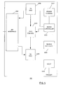
- FIG. 6 is a block diagram of the tamper RTC circuit 140.
- the tamper RTC 140 includes a SM bus interface 170 used by management ASIC 160 or by a power on reset signal to gain access to the tamper RTC circuit 140.
- the system bus interface 170 communicates with a real time clock 178 and a latch 180.
- the latch 180 receives tamper event signals 132 and 134 via receivers 172 and 174 through a logic circuit 176.
- the tamper RTC circuit 140 receives either a cover tamper event signal or a RF tamper event signal the contents of RTC 178 are transferred and held in latch 180.
- the time stamp for latch 180 can then be read by software via the SM bus interface 170.
- a LAN Leash tamper is detected by management ASIC 160, it then drives a request to 140 to obtain the time stamp.
- RTC 140 sends the contents for RTC 178 to SM bus interface 170, over the SM bus 64 to management ASIC 160.
- the management ASIC 160 receives the cover tamper signal.
- the management ASCI 160 duplicates the function of the MAC 100 to send alert packets to the physical layer 102.
- an event occurs such as a cover tamper signal 132 or an RF tamper signal 134
- the management ASIC 160 creates an event packet and sends a predefined message to a system administrator.
- the management ASIC 160 obtains a timestamp for the event packet by issuing a command to the tamper RTC circuit 140 on the SM bus 64.
- the management ASIC adds the timestamp to the packet and generates a network packet.
- a network packet 200 is illustrated by Figure 7.
- the network packet 200 comprises a header section 202 and a data section 204.
- the header section 202 contains in a preferred embodiment, internet, UDP, and MAC headers.
- the data section 204 in a preferred embodiment comprises the type of event, timestamp, and universal unique identification (UUID).
- the timestamp provides the critical information for determining when a tamper event has occurred.
- the LAN adapter 94 further includes a connector 110 such as a RJ45 connector which is the physical interface between the adapter 94 and cable 36.
- a connector 110 such as a RJ45 connector which is the physical interface between the adapter 94 and cable 36.
- An alternative embodiment to the LAN adapter 94 could be, for example, a LAN connector or connection embedded or integrated on the planar 20.
- the LAN connector could also include all the same connections and components as the adapter 94.
- the MAC 100 and Physical layer 102 could be combined into a signal chip.
- the connection to Management ASIC 160 could be MII bus or other type of bus.
- another option is combining the Management ASIC 160 into the single chip MAC and physical layer.
- a first type of tamper event could be a switch connected to the chassis of the computer.
- a toggle switch 130 is connected to chassis 19 in a manner such that when the cover 15 is used to enclose the unit the toggle switch 130 is closed.
- the toggle switch 130 changes position indicating the cover has been removed on the cover tamper signal 132.
- the cover tamper signal 132 is connected to the tamper RTC 140, which results in a tamper RTC 140 latching or holding the current value of the clock.
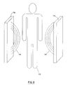
- a second type of tamper event is when a computer is removed from a building or room.
- Figure 8 which illustrates a person 128 carrying machine 12 through portals 130 and 132 which are located in a building or room.
- the portal 130 and 132 emit a continuous RF field 134 and 136.
- the RFID EEPROM 90 in the computer detects the presence of the field, it sends a RF tamper signal 134 to an input of tamper RTC circuit 140 (Fig. 4), which results in the tamper RTC circuit 140 latching or holding the current value of the clock.
- the tamper RTC circuit 140 is initialized and synchronized by power on self test (POST) via the SM bus 64. Programming of the counter is handled by system POST/BIOS during system initialization and is OS independent. In addition, in a preferred embodiment the programming requires use of Privilege access password (PAP) to ensure only a system administrator changes values.
- PAP Privilege access password
- Fig. 9 is a flow diagram of the operation of the system.
- POST Power On Self Test
- the tamper RTC circuit 140 determines if a tamper event has occurred, via step 152. If there are no tamper events the system RTC 52 ( Figure 3) and the duplicate RTC 140 are synchronized, via step 150. If a tamper event occurred, then POST locks the system and displays a message indicating the need to enter PAP, via step 156 and waits for a password, via step 156. After a password is entered POST provides access to timestamp information in RTC circuit 140. After the access it then resets latches 172 and 174, via step 164 and resynchronizes system RTC circuit 52 to the tamper RTC circuit 140 via step 158.
- POST Power On Self Test
- a system and method in accordance with the present invention provides a computer system which has the ability to functionally detect and record the time of a tamper event.
- the triggering events are tamper events which can be detected by the computer system.
- the tamper event could be as simple as a toggle switch being activated when the cover of the personal computer is removed.
- the computer system in a preferred embodiment includes a tamper detection switch mounted within the enclosure and operatively connected with a logic unit to retain the time of the tamper event.
- the personal computer in a preferred embodiment also sends network alerts when the cover is removed.
- the computer system can also be coupled to a remote computer via a data communication link.
- a tamper real time clock (RTC) circuit is operatively connected with logic to obtain and send the time of the event as part of the network alert.
- the system RTC could modify the system RTC such that upon detection of the tamper event the contents of the system RTC could be transferred to a non-volatile memory, where the contents could then be read by software.
- the management ASIC 160 could also read the system RTC to obtain the time stamp if the RTC had an SM bus interface.
- the RTC could provide numerous non-volatile memory devices to store numerous events. In addition to the time stamp, the source of the event would also be stored.
Landscapes
- Engineering & Computer Science (AREA)
- Computer Hardware Design (AREA)
- Theoretical Computer Science (AREA)
- General Engineering & Computer Science (AREA)
- Computer Security & Cryptography (AREA)
- General Physics & Mathematics (AREA)
- Physics & Mathematics (AREA)
- Software Systems (AREA)
- Computer Networks & Wireless Communication (AREA)
- Signal Processing (AREA)
- Computing Systems (AREA)
- Storage Device Security (AREA)
- Small-Scale Networks (AREA)
- Debugging And Monitoring (AREA)
Applications Claiming Priority (2)
| Application Number | Priority Date | Filing Date | Title |
|---|---|---|---|
| US108416 | 1998-07-01 | ||
| US09/108,416 US6357007B1 (en) | 1998-07-01 | 1998-07-01 | System for detecting tamper events and capturing the time of their occurrence |
Publications (3)
| Publication Number | Publication Date |
|---|---|
| EP0969346A2 true EP0969346A2 (de) | 2000-01-05 |
| EP0969346A3 EP0969346A3 (de) | 2000-08-23 |
| EP0969346B1 EP0969346B1 (de) | 2003-05-28 |
Family
ID=22322062
Family Applications (1)
| Application Number | Title | Priority Date | Filing Date |
|---|---|---|---|
| EP99304992A Expired - Lifetime EP0969346B1 (de) | 1998-07-01 | 1999-06-24 | Überwachungssystem gegen Manipulation für Computer |
Country Status (7)
| Country | Link |
|---|---|
| US (1) | US6357007B1 (de) |
| EP (1) | EP0969346B1 (de) |
| CA (1) | CA2271534A1 (de) |
| DE (1) | DE69908245T2 (de) |
| IL (1) | IL129645A (de) |
| SG (1) | SG93207A1 (de) |
| TW (1) | TW523649B (de) |
Cited By (9)
| Publication number | Priority date | Publication date | Assignee | Title |
|---|---|---|---|---|
| EP1333352A3 (de) * | 2002-01-31 | 2004-12-22 | Fujitsu Limited | Datenverwaltungsmechanismus und -vorrichtung oder Karte mit Datenverwaltungsmechanismus |
| WO2006020152A1 (en) * | 2004-07-27 | 2006-02-23 | Intel Corporation | Method and apparatus for accessing information on an external machine-readable tag |
| WO2007075530A3 (en) * | 2005-12-16 | 2007-11-01 | Mikko Llc | Systems and methods for centralized custodial control |
| WO2009044355A3 (en) * | 2007-10-02 | 2009-06-04 | Nxp Bv | Multilevel timestamp detection circuit and method |
| WO2009099927A1 (en) | 2008-02-01 | 2009-08-13 | Apple Inc. | Consumer abuse detection system and method |
| US8278948B2 (en) | 2009-08-10 | 2012-10-02 | Apple Inc. | Mechanisms for detecting tampering of an electronic device |
| US8405512B2 (en) | 2008-02-01 | 2013-03-26 | Apple Inc. | System and method for accessing diagnostic information |
| EP2224641A3 (de) * | 2009-02-27 | 2013-12-11 | Insta Elektro GmbH | Elektrisches/elektronisches Installationsgerät |
| WO2015073495A1 (en) * | 2013-11-14 | 2015-05-21 | Microchip Technology Incorporated | Integrated circuit device with tamper dtection input and having real time clock and calendar logging thereof |
Families Citing this family (32)
| Publication number | Priority date | Publication date | Assignee | Title |
|---|---|---|---|---|
| US6647497B1 (en) * | 1999-03-31 | 2003-11-11 | International Business Machines Corporation | Method and system for secure computer system transfer |
| US6671722B1 (en) * | 1999-07-08 | 2003-12-30 | Intel Corporation | Stack-less, CPU-less creation of valid SNMP-trap packets |
| US6765877B1 (en) | 1999-08-30 | 2004-07-20 | Cisco Technology, Inc. | System and method for detecting unidirectional links |
| US7096496B1 (en) * | 1999-12-06 | 2006-08-22 | Lenovo (Singapore) Pte. Ltd. | Method and system for improved computer security utilizing dynamically variable security profile |
| US6470031B1 (en) * | 2000-09-05 | 2002-10-22 | Coactive Networks, Inc. | Method and apparatus for accurate packet time stamping |
| FR2819070B1 (fr) * | 2000-12-28 | 2003-03-21 | St Microelectronics Sa | Procede et dispositif de protection conte le piratage de circuits integres |
| US7778281B2 (en) * | 2001-04-27 | 2010-08-17 | Panasonic Corporation | Wireless communication apparatus |
| US7287169B2 (en) * | 2002-10-10 | 2007-10-23 | Stmicroelectronics, Inc. | Electronic device and timer therefor with tamper event stamp features and related methods |
| WO2004111918A1 (en) * | 2003-06-09 | 2004-12-23 | Brush Industries, Inc. | Card reader/writer devices and methods |
| US7409563B2 (en) * | 2003-07-22 | 2008-08-05 | Lockheed Martin Corporation | Method and apparatus for preventing un-authorized attachment of computer peripherals |
| JP2005236605A (ja) * | 2004-02-19 | 2005-09-02 | Hitachi Communication Technologies Ltd | 暗号化通信装置 |
| US8621597B1 (en) * | 2004-10-22 | 2013-12-31 | Xilinx, Inc. | Apparatus and method for automatic self-erasing of programmable logic devices |
| TW200641695A (en) * | 2005-05-18 | 2006-12-01 | Elitegroup Computer Systems Co Ltd | Method and related apparatus for enhancing information security of a computer system |
| KR20140109513A (ko) * | 2006-05-09 | 2014-09-15 | 인터디지탈 테크날러지 코포레이션 | 무선 장치에 대한 안전 시간 기능 |
| US7987512B2 (en) * | 2006-05-19 | 2011-07-26 | Microsoft Corporation | BIOS based secure execution environment |
| US20080005560A1 (en) * | 2006-06-29 | 2008-01-03 | Microsoft Corporation | Independent Computation Environment and Provisioning of Computing Device Functionality |
| US20080184341A1 (en) * | 2007-01-29 | 2008-07-31 | David Jaroslav Sebesta | Master-Slave Protocol for Security Devices |
| US8151118B2 (en) * | 2007-01-29 | 2012-04-03 | Microsoft Corporation | Master-slave security devices |
| US8209561B2 (en) | 2007-07-20 | 2012-06-26 | Seiko Epson Corporation | Real time clock and method for recording data in real time clock |
| IL193504A (en) * | 2008-08-17 | 2013-02-28 | Michael Braiman | RF coded communication system |
| US8788867B2 (en) | 2011-01-07 | 2014-07-22 | Anue Systems, Inc. | Systems and methods for playback of detected timing events |
| US8683254B2 (en) | 2011-01-07 | 2014-03-25 | Anue Systems, Inc. | Systems and methods for precise event timing measurements |
| US8850259B2 (en) | 2011-01-07 | 2014-09-30 | Anue Systems, Inc. | Systems and methods for precise generation of phase variation in digital signals |
| US8533518B2 (en) * | 2011-01-07 | 2013-09-10 | Anue Systems, Inc. | Systems and methods for precise timing measurements using high-speed deserializers |
| DE102011007572A1 (de) | 2011-04-18 | 2012-10-18 | Siemens Aktiengesellschaft | Verfahren zur Überwachung eines Tamperschutzes sowie Überwachungssystem für ein Feldgerät mit Tamperschutz |
| US9007182B2 (en) * | 2012-02-15 | 2015-04-14 | Honeywell International Inc. | Protecting packages from tampering |
| CN104750592A (zh) * | 2013-12-31 | 2015-07-01 | 鸿富锦精密工业(武汉)有限公司 | 盖体开启侦测系统 |
| CN105095799A (zh) * | 2014-04-30 | 2015-11-25 | 鸿富锦精密工业(武汉)有限公司 | 电子装置 |
| CA3010282A1 (en) * | 2015-12-31 | 2017-07-06 | Eksper Bilisim Hizmetleri Sanayi Ve Ticaret Limited Sirketi | A device for detection the foreign objects placed, jamming the data with disruptive signals, issuing warning notices and recording the events in order to protect the data on the cards used in the payment stations |
| US10538371B2 (en) * | 2018-03-28 | 2020-01-21 | In-Tech Enterprise Ltd. | Container security system |
| US11222515B2 (en) * | 2019-02-13 | 2022-01-11 | Lenovo (Singapore) Pte. Ltd. | Device tamper detection |
| US12362265B2 (en) * | 2021-09-08 | 2025-07-15 | Nuvoton Technology Corporation | Integrated circuit (IC) and electronic apparatus |
Family Cites Families (8)
| Publication number | Priority date | Publication date | Assignee | Title |
|---|---|---|---|---|
| US5475625A (en) * | 1991-01-16 | 1995-12-12 | Siemens Nixdorf Informationssysteme Aktiengesellschaft | Method and arrangement for monitoring computer manipulations |
| WO1993006695A1 (en) | 1991-09-23 | 1993-04-01 | Z-Microsystems | Enhanced security system for computing devices |
| US5388156A (en) | 1992-02-26 | 1995-02-07 | International Business Machines Corp. | Personal computer system with security features and method |
| US5287519A (en) | 1992-09-17 | 1994-02-15 | International Business Machines Corp. | LAN station personal computer system with controlled data access for normal and unauthorized users and method |
| JP3165366B2 (ja) * | 1996-02-08 | 2001-05-14 | 株式会社日立製作所 | ネットワークセキュリティシステム |
| US5970227A (en) | 1996-04-30 | 1999-10-19 | International Business Machines Corp. | Wireless proximity detector security feature |
| US5712973A (en) * | 1996-05-20 | 1998-01-27 | International Business Machines Corp. | Wireless proximity containment security |
| US5991881A (en) * | 1996-11-08 | 1999-11-23 | Harris Corporation | Network surveillance system |
-
1998
- 1998-07-01 US US09/108,416 patent/US6357007B1/en not_active Expired - Lifetime
-
1999
- 1999-04-28 IL IL12964599A patent/IL129645A/xx not_active IP Right Cessation
- 1999-05-12 CA CA002271534A patent/CA2271534A1/en not_active Abandoned
- 1999-06-14 SG SG9902911A patent/SG93207A1/en unknown
- 1999-06-24 EP EP99304992A patent/EP0969346B1/de not_active Expired - Lifetime
- 1999-06-24 DE DE69908245T patent/DE69908245T2/de not_active Expired - Fee Related
- 1999-06-25 TW TW088110755A patent/TW523649B/zh not_active IP Right Cessation
Cited By (22)
| Publication number | Priority date | Publication date | Assignee | Title |
|---|---|---|---|---|
| EP1333352A3 (de) * | 2002-01-31 | 2004-12-22 | Fujitsu Limited | Datenverwaltungsmechanismus und -vorrichtung oder Karte mit Datenverwaltungsmechanismus |
| WO2006020152A1 (en) * | 2004-07-27 | 2006-02-23 | Intel Corporation | Method and apparatus for accessing information on an external machine-readable tag |
| GB2430786A (en) * | 2004-07-27 | 2007-04-04 | Intel Corp | Method and apparatus for accessing information on an external machine-readable tag |
| JP2008508599A (ja) * | 2004-07-27 | 2008-03-21 | インテル・コーポレーション | 外部の機械読取り可能タグの情報にアクセスするための方法及び装置 |
| US7366806B2 (en) | 2004-07-27 | 2008-04-29 | Intel Corporation | Method and apparatus for RFID tag wherein memory of RFID tag is partitioned into two sections for reading using wireless interface and writing using bus |
| CN1993701B (zh) * | 2004-07-27 | 2010-12-29 | 英特尔公司 | 用于访问在外部机器可读标签上的信息的方法和设备 |
| WO2007075530A3 (en) * | 2005-12-16 | 2007-11-01 | Mikko Llc | Systems and methods for centralized custodial control |
| WO2009044355A3 (en) * | 2007-10-02 | 2009-06-04 | Nxp Bv | Multilevel timestamp detection circuit and method |
| US8504326B2 (en) | 2007-10-02 | 2013-08-06 | Nxp B.V. | Multilevel timestamp detection circuit and method |
| US20100198558A1 (en) * | 2007-10-02 | 2010-08-05 | Nxp B.V. | Multilevel timestamp detection circuit and method |
| CN101960461A (zh) * | 2008-02-01 | 2011-01-26 | 苹果公司 | 消费者不恰当使用检测系统和方法 |
| US7880591B2 (en) | 2008-02-01 | 2011-02-01 | Apple Inc. | Consumer abuse detection system and method |
| KR101051246B1 (ko) * | 2008-02-01 | 2011-07-21 | 애플 인크. | 소비자 남용 검출 시스템 및 방법 |
| US8063765B2 (en) | 2008-02-01 | 2011-11-22 | Apple Inc. | Consumer abuse detection system and method |
| US8405512B2 (en) | 2008-02-01 | 2013-03-26 | Apple Inc. | System and method for accessing diagnostic information |
| WO2009099927A1 (en) | 2008-02-01 | 2009-08-13 | Apple Inc. | Consumer abuse detection system and method |
| CN101960461B (zh) * | 2008-02-01 | 2013-12-18 | 苹果公司 | 消费者不恰当使用检测系统和方法 |
| EP2224641A3 (de) * | 2009-02-27 | 2013-12-11 | Insta Elektro GmbH | Elektrisches/elektronisches Installationsgerät |
| US8278948B2 (en) | 2009-08-10 | 2012-10-02 | Apple Inc. | Mechanisms for detecting tampering of an electronic device |
| US8736286B2 (en) | 2009-08-10 | 2014-05-27 | Apple Inc. | Mechanisms for detecting tampering of an electronic device |
| WO2015073495A1 (en) * | 2013-11-14 | 2015-05-21 | Microchip Technology Incorporated | Integrated circuit device with tamper dtection input and having real time clock and calendar logging thereof |
| US9602895B2 (en) | 2013-11-14 | 2017-03-21 | Microchip Technology Incorporated | Integrated circuit device with tamper detection input and having real time clock calendar logging thereof |
Also Published As
| Publication number | Publication date |
|---|---|
| EP0969346A3 (de) | 2000-08-23 |
| US6357007B1 (en) | 2002-03-12 |
| IL129645A0 (en) | 2000-02-29 |
| CA2271534A1 (en) | 2000-01-01 |
| DE69908245T2 (de) | 2004-04-08 |
| IL129645A (en) | 2003-06-24 |
| DE69908245D1 (de) | 2003-07-03 |
| TW523649B (en) | 2003-03-11 |
| SG93207A1 (en) | 2002-12-17 |
| EP0969346B1 (de) | 2003-05-28 |
Similar Documents
| Publication | Publication Date | Title |
|---|---|---|
| EP0969346B1 (de) | Überwachungssystem gegen Manipulation für Computer | |
| US6105136A (en) | Computer system which is disabled when it is disconnected from a network | |
| US6263440B1 (en) | Tracking and protection of display monitors by reporting their identity | |
| US5945915A (en) | Computer system for sending an alert signal over a network when a cover of said system has been opened | |
| US6218941B1 (en) | Method and system for detecting an authorized tamper event | |
| US6154790A (en) | Monitoring and reporting hard disk drives identification using radio frequency | |
| US6170059B1 (en) | Tracking memory modules within a computer system | |
| US6021493A (en) | System and method for detecting when a computer system is removed from a network | |
| US6026492A (en) | Computer system and method to disable same when network cable is removed | |
| KR100523967B1 (ko) | 캐비넷보안상태감지시스템및방법 | |
| US6289456B1 (en) | Hood intrusion and loss of AC power detection with automatic time stamp | |
| US6647497B1 (en) | Method and system for secure computer system transfer | |
| US6288645B1 (en) | Electronic location tag | |
| US6282642B1 (en) | System for presetting a first or second remote boot protocol by a computer remotely receiving and storing a boot parameter prior to being powered on | |
| US8484327B2 (en) | Method and system for generic real time management of devices on computers connected to a network | |
| US6002427A (en) | Security system with proximity sensing for an electronic device | |
| US6601097B1 (en) | Method and system for determining the physical location of computers in a network by storing a room location and MAC address in the ethernet wall plate | |
| US6397249B1 (en) | Data processing system and method for determining a physical location of a client computer system | |
| US9152826B2 (en) | Damage detection for an anti-theft interface | |
| US6263441B1 (en) | Real-time alert mechanism for signaling change of system configuration | |
| EP0850441A1 (de) | Verfahren zur überwachung eines rechnersystems | |
| US8010617B2 (en) | Securing serial console redirection via serial-over-LAN (SOL) | |
| US6628663B1 (en) | System and method for permitting a dumb device to create and transmit network packets | |
| US7076538B2 (en) | Method and system for disguising a computer system's identity on a network | |
| US6370650B1 (en) | Method and system in a data processing system for deactivating a password requirement utilizing a wireless signal |
Legal Events
| Date | Code | Title | Description |
|---|---|---|---|
| PUAI | Public reference made under article 153(3) epc to a published international application that has entered the european phase |
Free format text: ORIGINAL CODE: 0009012 |
|
| AK | Designated contracting states |
Kind code of ref document: A2 Designated state(s): DE FR GB IE IT |
|
| AX | Request for extension of the european patent |
Free format text: AL;LT;LV;MK;RO;SI |
|
| PUAL | Search report despatched |
Free format text: ORIGINAL CODE: 0009013 |
|
| AK | Designated contracting states |
Kind code of ref document: A3 Designated state(s): AT BE CH CY DE DK ES FI FR GB GR IE IT LI LU MC NL PT SE |
|
| AX | Request for extension of the european patent |
Free format text: AL;LT;LV;MK;RO;SI |
|
| 17P | Request for examination filed |
Effective date: 20010124 |
|
| AKX | Designation fees paid |
Free format text: DE FR GB IE IT |
|
| GRAH | Despatch of communication of intention to grant a patent |
Free format text: ORIGINAL CODE: EPIDOS IGRA |
|
| GRAH | Despatch of communication of intention to grant a patent |
Free format text: ORIGINAL CODE: EPIDOS IGRA |
|
| GRAA | (expected) grant |
Free format text: ORIGINAL CODE: 0009210 |
|
| AK | Designated contracting states |
Designated state(s): DE FR GB IE IT |
|
| REG | Reference to a national code |
Ref country code: GB Ref legal event code: FG4D |
|
| REG | Reference to a national code |
Ref country code: IE Ref legal event code: FG4D |
|
| REF | Corresponds to: |
Ref document number: 69908245 Country of ref document: DE Date of ref document: 20030703 Kind code of ref document: P |
|
| ET | Fr: translation filed | ||
| PLBE | No opposition filed within time limit |
Free format text: ORIGINAL CODE: 0009261 |
|
| STAA | Information on the status of an ep patent application or granted ep patent |
Free format text: STATUS: NO OPPOSITION FILED WITHIN TIME LIMIT |
|
| 26N | No opposition filed |
Effective date: 20040302 |
|
| PGFP | Annual fee paid to national office [announced via postgrant information from national office to epo] |
Ref country code: FR Payment date: 20050620 Year of fee payment: 7 |
|
| PGFP | Annual fee paid to national office [announced via postgrant information from national office to epo] |
Ref country code: IT Payment date: 20060630 Year of fee payment: 8 |
|
| REG | Reference to a national code |
Ref country code: GB Ref legal event code: 732E |
|
| REG | Reference to a national code |
Ref country code: FR Ref legal event code: TP |
|
| REG | Reference to a national code |
Ref country code: FR Ref legal event code: ST Effective date: 20070228 |
|
| PG25 | Lapsed in a contracting state [announced via postgrant information from national office to epo] |
Ref country code: FR Free format text: LAPSE BECAUSE OF NON-PAYMENT OF DUE FEES Effective date: 20060630 |
|
| PGFP | Annual fee paid to national office [announced via postgrant information from national office to epo] |
Ref country code: IE Payment date: 20080613 Year of fee payment: 10 Ref country code: DE Payment date: 20080703 Year of fee payment: 10 |
|
| PGFP | Annual fee paid to national office [announced via postgrant information from national office to epo] |
Ref country code: GB Payment date: 20080625 Year of fee payment: 10 |
|
| PG25 | Lapsed in a contracting state [announced via postgrant information from national office to epo] |
Ref country code: IT Free format text: LAPSE BECAUSE OF NON-PAYMENT OF DUE FEES Effective date: 20070624 |
|
| GBPC | Gb: european patent ceased through non-payment of renewal fee |
Effective date: 20090624 |
|
| REG | Reference to a national code |
Ref country code: IE Ref legal event code: MM4A |
|
| PG25 | Lapsed in a contracting state [announced via postgrant information from national office to epo] |
Ref country code: IE Free format text: LAPSE BECAUSE OF NON-PAYMENT OF DUE FEES Effective date: 20090624 |
|
| PG25 | Lapsed in a contracting state [announced via postgrant information from national office to epo] |
Ref country code: GB Free format text: LAPSE BECAUSE OF NON-PAYMENT OF DUE FEES Effective date: 20090624 |
|
| PG25 | Lapsed in a contracting state [announced via postgrant information from national office to epo] |
Ref country code: DE Free format text: LAPSE BECAUSE OF NON-PAYMENT OF DUE FEES Effective date: 20100101 |