EP0969280A2 - Flexible Mehrzwek- Modularanordnung zur Verwendung mit einer Mehrheit von PGNAA Schüttgutanalysevorrichtungen - Google Patents
Flexible Mehrzwek- Modularanordnung zur Verwendung mit einer Mehrheit von PGNAA Schüttgutanalysevorrichtungen Download PDFInfo
- Publication number
- EP0969280A2 EP0969280A2 EP99304694A EP99304694A EP0969280A2 EP 0969280 A2 EP0969280 A2 EP 0969280A2 EP 99304694 A EP99304694 A EP 99304694A EP 99304694 A EP99304694 A EP 99304694A EP 0969280 A2 EP0969280 A2 EP 0969280A2
- Authority
- EP
- European Patent Office
- Prior art keywords
- passageway
- primary module
- bulk material
- neutron
- radiation
- Prior art date
- Legal status (The legal status is an assumption and is not a legal conclusion. Google has not performed a legal analysis and makes no representation as to the accuracy of the status listed.)
- Withdrawn
Links
Images


Classifications
-
- G—PHYSICS
- G01—MEASURING; TESTING
- G01N—INVESTIGATING OR ANALYSING MATERIALS BY DETERMINING THEIR CHEMICAL OR PHYSICAL PROPERTIES
- G01N23/00—Investigating or analysing materials by the use of wave or particle radiation, e.g. X-rays or neutrons, not covered by groups G01N3/00 – G01N17/00, G01N21/00 or G01N22/00
- G01N23/22—Investigating or analysing materials by the use of wave or particle radiation, e.g. X-rays or neutrons, not covered by groups G01N3/00 – G01N17/00, G01N21/00 or G01N22/00 by measuring secondary emission from the material
- G01N23/221—Investigating or analysing materials by the use of wave or particle radiation, e.g. X-rays or neutrons, not covered by groups G01N3/00 – G01N17/00, G01N21/00 or G01N22/00 by measuring secondary emission from the material by activation analysis
- G01N23/222—Investigating or analysing materials by the use of wave or particle radiation, e.g. X-rays or neutrons, not covered by groups G01N3/00 – G01N17/00, G01N21/00 or G01N22/00 by measuring secondary emission from the material by activation analysis using neutron activation analysis [NAA]
Definitions
- the present invention generally pertains to bulk material analyzers and is particularly directed to an improved modular assembly for bulk material analyzers of the type in which the bulk material is transported through an analysis region located between a radiation source and a radiation detector in the bulk material analyzer.
- the analysis region is usually referred to herein as an activation region.
- the radiation source includes one or more neutron sources and the radiation detector includes one or more gamma-ray detectors that produce signals which are processed to provide a measurement of the elemental content of the bulk material.
- the bulk material is bombarded with neutrons, secondary emissions of gamma-rays are produced from the bulk material. Different characteristic spectra of gamma-ray energy are produced from different elements of the bulk material.
- PNAA prompt gamma-ray neutron activation analysis
- the bulk material analyzer assembly In addition to containing the radiation source and the radiation detector, the bulk material analyzer assembly necessarily includes a large quantity of radiation shielding material in order to protect persons using the bulk material analyzer from harmful doses of radiation.
- the required quantity of radiation shielding is such that the bulk material analyzer assembly is so large that the assembly is not easily handled for transportation from one site to another.
- U.S. Patent No. 5,396.071 to Atwell et al. describes a modular assembly for a PGNAA bulk material analyzer of the type in which bulk material is transported on a conveyor belt through an activation region located between at least one radiation source and at least one radiation detector within the bulk material analyzer.
- Such assembly includes container means that include a lower primary module containing radiation shielding material and defining either at least one radiation source cavity or at least one radiation detector cavity; and an upper primary module containing radiation shielding material and defining the other of either the at least one radiation source cavity or the at least one radiation detector cavity that is not defined by the lower primary module.
- the lower primary module and the upper primary module are so shaped that the passageway is delimited by placement of the upper primary module upon the lower primary module; and portions of the lower primary module are shaped for delimiting the sides of a trough that is contoured for accommodating passage of the conveyor belt through the activation region.
- the trough-delimiting portions of the lower module are inclined outwardly from the bottom of the passageway to accommodate a passage on a conveyor belt having a complementary contour.
- the present invention provides an assembly for analysis of bulk material moving through an activation region located between at least one radiation source and at least one radiation detector, the assembly comprising at least two replaceable side modules, each containing radiation shielding material, for sandwiching between a first primary module that contains radiation shielding material and includes means for retaining the at least one radiation source and a second primary module that contains radiation shielding material and includes means for retaining the at least one radiation detector, to separate the first primary module from the second primary module and delimit a passageway for movement of the bulk material through the activation region.
- the assembly may further include at least one replaceable liner placed on a said side module to further delimit the passageway, and the at least one replaceable liner may include a material having a characteristic of at least one of neutron moderating, neutron absorbing or neutron reflecting.
- the bulk material analyzer assembly of the present invention can be modified for use with large ranges of conveyor belt sizes and shapes, of bulk material depths, and/or proximity of the radiation detector(s) to the bulk material merely by replacing the less complex and less expensive replaceable side modules and/or the replaceable liners. In some instances it is desirable to adjust the depth of the bulk material and/or the proximity of the radiation detector(s) to the bulk material in order to enhance the uniformity of measurement sensitivity throughout the portion of the activation region that is occupied by the bulk material.
- the present invention further provides an assembly for a bulk material analyzer of the type in which bulk material is transported through an activation region located between at least one radiation source and at least one radiation detector within the bulk material analyzer, and in which container means define a passageway for enabling passage of the bulk material through the activation region and include means for retaining the at the least one radiation detector and means for retaining the at least one radiation source, said assembly comprising a replaceable liner of neutron moderating, absorbing and/or reflecting material for placement adjacent the passageway on a surface of the container means; wherein the liner has a variable neutron moderating, absorbing and/or reflecting characteristic with respect to distance from the longitudinal axis of the passageway.
- the material typically used in conveyor belts has such a high proportion of hydrogen that when the conveyor belt is disposed between the neutron source and the activation region, the neutron moderating effect of the hydrogen in the conveyor belt so combines with the higher neutron moderating effect resulting from the higher hydrogen content of the bulk material as to make it more difficult to achieve uniformity of measurement sensitivity throughout the portion of the activation region that is occupied by the bulk material.
- the present invention provides an assembly for a bulk material analyzer of the type in which bulk material is transported on a conveyor belt through an activation region located between at least one neutron source and at least one gamma-ray detector within the bulk material analyzer, and in which signals produced by the gamma-ray detector in response to gamma-rays secondarily emitted from the bulk material in response to bombardment of neutrons are processed in order to determine the elemental content of the bulk material, said assembly comprising container means defining a passageway for enabling passage of the conveyor belt through the activation region and including means for retaining the at least one gamma-ray detector and means for retaining the at least one neutron-radiation source; and radiation shielding material disposed within the container means; wherein the means for retaining the at least one neutron-radiation source is disposed above the passageway; wherein the means for retaining the at least one gamma-ray detector is disposed below the passageway; and wherein a neutron reflecting material is disposed between
- the present invention provides an improved method of analyzing the composition of bulk material having a hydrogen content exceeding four percent by weight, comprising the steps of;
- the present invention still further provides an assembly for a bulk material analyzer of the type in which bulk material is transported on a conveyor belt through an activation region located between at least one radiation source and at least one radiation detector within the bulk material analyzer, said assembly comprising container means defining a passageway for enabling passage of the conveyor belt through the activation region and including means for retaining the at least one radiation detector and means for retaining the at least one radiation source; wherein the means for retaining the at least one radiation detector includes a channel disposed approximately parallel to the bottom of the passageway and transverse to the longitudinal axis of the passageway.
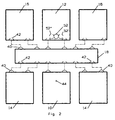
- a preferred embodiment of a modular bulk material analyzer assembly includes a lower primary module 10, an upper primary module 12, a pair of lower secondary modules 14, a pair of upper secondary modules 16, a set of replaceable side modules 18 and a set of replaceable liners 20, 21, 22.
- Each of the modules 10, 12, 14, 16, 18 contains radiation shielding material.
- the secondary modules 14, 16 are placed upstream and down stream of the primary modules 10, 12 for the purpose of lowering the radiation flux outside of the assembly.
- the walls of the modules 10, 12, 14, 16, 18 preferably are made of molded fiber reinforced plastic, plastic sheet, or sheet metal.
- a plurality of smaller, personally portable, differently-dimensioned-and-shaped, side modules of neutron shielding material are placed between the lower primary module 10 and the upper primary module 12 on each side of the passageway 28 in the respective volumes of space otherwise occupied by the side modules 18 in the preferred embodiment shown in the figures of the Drawing.
- the lower primary module 10 defines either at least one radiation source cavity or at least one radiation detector channel; and the upper primary module 12 defines the other of either the at least one radiation source cavity or the at least one radiation detector channel that is not defined by the lower primary module 10, as further described below with reference to FIGS. 5 and 6.
- a conveyor belt 24 transports bulk material 26 through an activation region located within a passageway 28 that is defined between the lower primary module 10, the upper primary module 12 and the set of replaceable side modules 18.
- Each side module 18 preferably extends from the passageway 28 to a plane that includes the outside surfaces of the lower primary module 10 and the upper primary module 12, thereby filling the space between the lower module10 and upper module 12 except for the space occupied by the passageway 28 and the replaceable liners 20, 21, 22.
- each side module 18 has a smaller longitudinal cross-section than that of the lower modules 10, 14 and the upper modules 12, 16 (as seen in FIG. 3), each side module 18 can extend over the entire length of the assembly, as shown in FIG. 2, and still be of a size and weight comparable to those of the respective lower and upper modules; thereby minimizing cost by reducing the number of modules and also providing a more rugged and rigid construction.
- Opposing surfaces 30 of the respective replaceable side modules 18 are shaped for delimiting the sides 32 of a trough 34 that is contoured for accommodating passage of the conveyor belt 24 through the passageway 28.
- the trough 34 may be shaped to complement the shape of the conveyor belt 24, as shown in FIG. 5, or the trough 34 may be rounded upward from its longitudinal center, and/or have vertical sides (not shown), to accommodate passage of a flat conveyor belt.
- the bottom of the passageway 28 is delimited by a bottom-of-the-trough portion 36 of the lower primary module 10 and the top of the passageway 28 is delimited by a portion 38 of the upper primary module 12.
- the trough-delimiting surfaces 30 of the replaceable side modules 12 are inclined outwardly from the bottom of the passageway 28 in order to accommodate the passage of a conveyor belt 24 that has outwardly inclined side walls.
- the angle of inclination of the trough-delimiting surfaces 30 is selected to correspond to the angle of inclination of the side walls of the conveyor belt 24.
- the lower primary module 10 and upper primary module 12 are so dimensioned that they 10, 12 may be used with the largest belt sizes, as well as for much smaller belt sizes, for example one-half to one-third of the size of the large belt.
- the upward facing surfaces of the lower modules 10, 14 and the upward facing surfaces of the replaceable side modules 18 include protruding alignment members 40 and the downward facing surfaces of the side modules 18, and the downward facing surfaces of the upper modules 12, 16 include alignment recesses 42 that complement the protruding alignment members 40 to assure accurate placement of the side modules 14 upon the lower modules 10, 14 and accurate placement of the upper modules 12, 16 upon the side modules 18.
- the alignment members 40 and the alignment recesses 42 are shown as generally convex bumps and concave dimples respectively.
- any form of male and female combination may be used, such as combinations of projections and sockets, ridges and grooves, pegs and holes, and tenons and mortises.
- abutting module surfaces may have holes formed therein and a separate pin or dowel can be inserted into both holes as one module is lowered over and aligned with a another module.
- a separate pin or dowel can be inserted into both holes as one module is lowered over and aligned with a another module.
- placement and replacement of the modules is achieved by using a crane or other conventional lifting mechanism.
- the replaceable liners 20, 21, 22 of neutron moderating and/or absorbing and/or reflecting material are placed adjacent the passageway 28 and adjacent the side modules 18 and/or the lower primary module 10 and/or the upper primary module 12 for further delimiting the passageway 28 and/or the bottom and/or the sides of the trough 34 to accommodate passage of the conveyor belt 24 through the passageway 28 in accordance with the size and shape of the conveyor belt 24.
- the sides of the liners 20, 21 that support the conveyor belt 24 have a low friction surface with good wear characteristics.
- a liner 20 further delimiting the bottom portion of the trough 34 has an upper surface that is rounded upward from its longitudinal center (not shown) and/or the side liners 21 are shaped so that the side-of-the-trough-delimiting surfaces of the side liners 21 are vertical (not shown). In an alternative embodiment, the opposing surfaces 30 of the side modules 18 are vertical (not shown).
- the assembly does not include some or any of the replaceable liners 20, 21, 22 because the replaceable side modules 12 are so dimensioned and shaped that replaceable liners are not required for further-delimiting the passageway 28 in order to better accommodate passage of the conveyor belt 24 therethrough or to enhance the uniformity of measurement sensitivity throughout the portion of the activation region that is occupied by the bulk material.
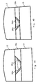
- a pair of replaceable sets of side modules 18a, 18b of different sizes and shapes are respectively placed between a given set of a lower primary module 10 and an upper primary module 12 for accommodating the passage of different sizes and shapes of conveyor belts 24a, 24b.
- the lower primary module 10 and the upper primary module 12 in the FIG. 4A embodiment are identical to the lower primary module 10 and the upper primary module 12 respectively in the FIG. 4B embodiment.
- the side modules 18a, 18b of each set are so dimensioned that said placement of the set of side modules 18a between the given set of the lower primary module 10 and the upper primary module 12, as shown in FIG. 4A, delimits the passageway 28a of the FIG.
- FIGS. 4A and 4B for larger belt widths increased spacing between the radiation source and the radiation detector is required.
- the replaceable-side-module assembly of the present invention enables increased spacing between the detector and source modules merely by replacing the side modules 18b of the FIG. 4B embodiment with the side modules 18a of the FIG. 4A embodiment. As the conveyor belt 24 becomes wider the side modules 18a also become narrower since the outside horizontal dimension of the overall assembly is constant over the full range of belt sizes.
- the outer dimensions of the overall assembly are such that for the largest belts, there is adequate space for shielding in the side modules 18a to keep the radiation emanating from the outside of the side modules to an acceptable level (usually 1 to 10 mR/hr).
- the thickness of the radiation shielding material in the side modules 18a, 18b may be determined either by computer modeling or empirically.
- the molds or fixtures for a family of assemblies includes one lower-module mold, one upper-module mold, and a set of side-module molds.
- a plurality of sets of replaceable liners 20, 21, 22 of neutron moderating and/or absorbing and/or reflecting material also are provided for placement adjacent the side modules 18, and the lower module 10 at the sides and the bottom of the passageway 28, with the liners 20, 21, 22 of each set being so dimensioned that placement of different sets of liners 20, 21, 22 adjacent a given set of the side modules 18 and the lower module 10 respectively further delimit the passageway to different heights and widths to thereby enable one to compensate for small differences in the sizes and shapes of conveyor belts without having to replace the side modules 18.
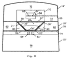
- the modular assembly of the present invention is used for bulk material analyzers of both the type in which neutron sources are disposed below the passageway and gamma-ray detectors are disposed above the passageway, as shown in FIG. 5, and the type in which neutron sources are disposed above the passageway and gamma-ray detectors are disposed below the passageway, as shown in FIG. 6.
- the lower primary module 10 includes a source cavity 44, gamma-ray shielding material 46, neutron moderating material 48 and neutron shielding material 50;
- the upper primary module 12 includes a tubular detector channel 52, neutron reflecting material 54 and neutron shielding material 56; and each of the replaceable side modules 18 includes neutron moderating material 58 and neutron shielding material 60.
- Opposing surfaces 30 of the respective replaceable side modules 18 are shaped for delimiting the sides 32 of a trough 34 that is contoured with outwardly inclined side walls for accommodating passage of the conveyor belt 24 through the passageway 28.
- a pair of neutron sources 62 are disposed in the source cavity 44 and a pair of gamma-ray detectors 64 are disposed in the detector channel 52.
- a plurality of such detector channels 52, 52', 52'' are respectively likewise disposed in the upper primary module 12, as indicated in FIG 2; and/or a plurality of such source channels 44 are respectively likewise disposed in the lower primary module 10.
- the gamma-ray shielding material 46 reduces the number of gamma rays that reach the detectors 64 from the neutron sources 62.
- the neutron sources 62 are Californium-252.
- electronic neutron sources 62 are provided.
- the source cavity 44 is a tubular channel 44 disposed transverse to the longitudinal axis of the passageway 28 and approximately parallel to the bottom of the passageway 28.
- the source cavity 44 is only approximately parallel to the bottom of the passageway 28 in that the source cavity 44 may be inclined toward the sides of the lower module 10 from at or near a position beneath the longitudinal axis of passageway 28 by up to fifteen degrees from a plane that is parallel to the upper surface of the lower module 10.
- the disposition of the sources 62 within the source cavity 44 may be varied in order vary the neutron moderation or shielding in accordance with the width of the conveyor belts 34.
- One or more neutron sources 62 may be placed at variable positions within the source cavity 44 with respect to the longitudinal axis of the passageway 28.
- the gamma-ray shielding material 46 and the neutron moderating material 48 extend laterally, as shown in FIG. 5, so as to provide substantially the same amount of gamma-ray shielding material 46 and moderating material 48 between the sources 62 and the passageway 28 when the sources 62 are placed at different distances from the longitudinal axis of the passageway 28.
- additional source cavities are disposed at different depths from the longitudinal axis of the passageway 28 so that the amount of neutron moderation provided by the neutron moderating material 48 can be varied by disposing one or more sources 62 in one or more selected source cavities.
- the distance from the longitudinal axis of the passageway 28 at which the sources 62 are placed can be used to control the uniformity of measurement sensitivity throughout the bulk material 26 within the activation region.
- the position(s) of the neutron source(s) is determined through the use of computer modeling to optimize said uniformity of measurement sensitivity.
- For wider conveyor belts 24 it often will be found that if a source 62 is placed directly beneath the longitudinal axis of the passageway 28, there may be higher measurement sensitivity near the center of the passageway 28 than near the sides of the passageway 28. In such a case multiple sources 62 may be placed on opposite sides of a vertical plane extending through the longitudinal axis of the passageway 28 in order to optimize the uniformity of measurement sensitivity throughout the bulk material 26 within the activation region.
- conveyor belt sizes can be accommodated by having the above-described degree of freedom in the placement of the neutron sources 62 such that the same lower module 10 may be used for a wide range of belt sizes and a wide range of bulk material types and profiles.
- belt widths range from 60 to 140 centimeters.
- the neutron sources 62 can be placed in accordance with a wider range of belt widths.
- the detector channel 52 is disposed transverse to the longitudinal axis of the passageway 28 and approximately parallel to the bottom of the passageway 28.
- the detector channel 52 is only approximately parallel to the bottom of the passageway 28 in that the detector channel 52 may be inclined toward the sides of the upper module 12 from at or near a position above the longitudinal axis of passageway 28 by up to ten-to-fifteen degrees from a plane that is parallel to the lower surface of the upper module 12.
- the detector channel 52 may be accessed though a door or a removable plug in at least one outside surface of the upper module 12 to thereby provide easy access to the detectors 64 for installation, adjustment, or replacement.
- One or more detectors 64 can be placed at any desired location in the detector channel 52.
- Each of the detectors 64 has relatively uniform end-to-end sensitivity variations of less than one-half the energy resolution of the detector and is disposed in the channel 52 with its longitudinal axis disposed approximately parallel to the bottom of the passageway 28 and transverse to the longitudinal axis of the passageway 28.
- Two detectors may be placed end to end with their contact point in a vertical plane that extends through the longitudinal axis of the passageway 28 or they may disposed at opposite sides of said vertical plane.
- Means are also disposed in the detector channel 52 to at least temporarily restrain the detectors 64 from movement within the detector channel 52 in response to acceleration or vibration of the upper module 12.
- the detectors 64 were to be placed in a plane approximately parallel to the bottom of the passageway 28, but oriented with their longitudinal axes in the same longitudinal direction as the passageway 28, the detectors 64 would not be as accessible and the placement of the detectors 64 with respect to the vertical plane that extends through the longitudinal axis of the passageway 28 would also be limited.
- the distance from the longitudinal axis of the passageway 28 at which the detectors 64 are placed can be used to control the uniformity of measurement sensitivity throughout the bulk material 26 within the activation region.
- the position(s) of the detector(s) is determined through the use of computer modeling to optimize said uniformity of measurement sensitivity. If, for example, it is found that the measurement sensitivity is higher at the vertical plane that extends through the longitudinal axis of the passageway 28 rather than toward the sides of the passageway 28, the detectors 64 may be moved within the detector channel 52 to be closer to the sides of the passageway 28 until a more uniform measurement sensitivity distribution is achieved. This optimal placement of the detectors 64 will be different for different width belts or flow channels, and/or for different types and profiles of bulk materials being analyzed.
- the above-described degree of freedom in the placement of the detectors 64 such that the same upper module 12 may be used for a wide range of belt sizes and a wide range of bulk material types and profiles.
- the radiation detectors 64 can be placed in accordance with a wider range of belt widths than the typical belt widths range of from 60 to 140 centimeters.
- the modular assembly of the present invention permits a single upper module design to be used for 1) different width belts, 2) for applications with different profiles of bulk material on the conveyor belt (i.e. flat, or humped in the middle), or 3) for different hydrogen content; and for each distinct application, the distance of the detector(s) 64 from the vertical plane that extends through the longitudinal axis of the passageway 28 may be optimized with no change to the mechanical design of the upper module 12.
- the modular assembly of the present invention also easily and inexpensively adapts to different applications requiring different analytical precision. Greater precision is obtained with greater numbers of detected gamma-ray counts.
- the number of counts may be increased by increasing the source strength or detector size but this is limited by the maximum number of counts that may be easily handled by the detector electronics without distortion of the gamma ray spectrum, especially due to pile up. Once this level is reached, then the number of gamma-ray counts may be further increased by increasing the number of detectors. Typically, the repeatability of an analysis may be improved as the square root of the number of useful gamma-ray counts or the number of detectors.
- the modular assembly of the present invention readily accommodates placement of different numbers of detectors 64 in the upper module 12.
- cost may be saved by using a single detector 64 placed at an optimal location in the detector channel 52, as determined by computer modeling, that enables a measurement accurately representing the material flowing through the analyzer to be obtained even if the material on the conveyor belt 34 is not homogeneous in the lateral direction.
- detectors 64 and/or more than one detector channel 52 it is desirable to use two or more detectors 64 and/or more than one detector channel 52 for applications where higher count rates are required to achieve the required precision or when it is desirable to lessen the source strength in order to lower external radiation for regulatory reasons, while maintaining the precision.
- detectors 64 or ones whose length is only a small fraction of the length of the detector channel 52 more than two detectors 64 may be placed in each detector channel 52.
- Replaceable liners 20, 21, 22 are placed adjacent the passageway 28 and adjacent the side modules 18, the lower primary module 10 and the upper primary module 12 for further delimiting the passageway 28 and the sides of the trough 34 to accommodate passage of the conveyor belt 24 through the passageway 28 in accordance with the size and shape of the conveyor belt 24.
- An individual liner on one or more sides of the passageway 28 may be varied in thickness and/or composition to fill the space between the bottom and side modules 10, 18 and the conveyor belt 24, and/or to optimize the moderation, absorption and/or reflection of neutrons to enhance the uniformity of measurement sensitivity throughout the portion of the activation region that is occupied by the bulk material.
- liners may comprise more than one material for a better optimization of a mechanical feature in combination with a particular neutron moderating, absorbing and/or reflecting, or gamma-ray absorption feature.
- a durable low friction layer of polyethylene overlaying a moderating material layer of bismuth for the bottom-of-the-trough liner 20 and the side liners 21.
- the replaceable bottom-of-the-trough liner 20, which is placed adjacent the passageway 28 on the lower primary module 10 to further delimit the bottom of the trough 34, includes neutron moderating and/or absorbing material, as determined by computer modeling for enhancing the uniformity of measurement sensitivity throughout the cross-section of the bulk material 26 being analyzed within the activation region without having to modify the lower module 10 to accomplish such enhancement.
- Graphite is a preferred neutron moderating material; and boron in combination with a material having a high hydrogen content, such as polyethylene, is a preferred neutron absorbing material.
- the replaceable liner 20 may have a variable neutron moderating characteristic with respect to distance from the longitudinal axis of the passageway 28 and/or a variable neutron absorbing characteristic with respect to distance from the longitudinal axis of the passageway 28. Such variation may be accomplished by varying the thickness of the liner 20 or by variable inclusion of selected constituent neutron moderating and/or absorbing materials when it is desired to provide a liner 20 of uniform thickness; or both variation techniques may be combined in a single liner 20. Such a variable-thickness liner 20 varies in thickness from approximately 1.25 to 2.5 centimeters.
- the thickness of the replaceable bottom-of-the-trough liner 20 is different for different circumstances. For example, when a small conveyor belt 24 is used or when the bulk material being analyzed has a low hydrogen content it is useful to increase the amount of neutron moderation provided by the bottom-of-the-trough liner 20 since the material being measured will provide little neutron moderation in those circumstances.
- Computer modeling is used to optimize the thickness and composition of the liner 20.
- at least fifty percent by volume of the liner 20 is made of made of low neutron absorbing materials, such as graphite or bismuth, because of their low neutron absorption and good neutron moderating properties.
- the liner 20 may be made of a material that has a high hydrogen content, such as polyethylene.
- the liner 20 may be made of a thermal neutron absorbing material such as boron.
- the boron may be any form that is mechanically convenient.
- the boron can be dispersed in a polymer, such an epoxy, or in a material comprising primarily carbon, hydrogen and oxygen.
- the boron can be embodied in boric acid. The important point is that the thickness and composition of the liner 20 is easily and inexpensively modified to accommodate a wide range of belt sizes and a wide range of hydrogen content of the bulk material 26 being analyzed since no changes are required in the source or detector modules.
- the replaceable side liners 21, which are placed adjacent the passageway 28 on the opposing surfaces 30 of the side modules 18 to further delimit the sides of the trough 34, include a neutron moderating and/or reflecting material, as determined by computer modeling in order to enhance the uniformity of measurement sensitivity throughout the cross-section of the bulk material 26 being analyzed within the activation region without having to modify the side modules 18 to accomplish such enhancement.
- a preferred neutron reflecting material is graphite, which has low neutron absorption, or bismuth, which also has a low neutron absorption characteristic and is a good gamma-ray absorber.
- the replaceable top liner 22 is made of neutron reflecting material and is placed adjacent the passageway 28 on the upper primary module 12 when such placement is determined by computer modeling to be required for enhancing the uniformity of measurement sensitivity throughout the cross-section of the bulk material 26 being analyzed within the activation region without having to modify the upper module 12 to accomplish such enhancement.
- the top liner 22 is usually used to reflect neutrons to thereby increase the measurement sensitivity in top portion of the bulk material 26 on the conveyor belt 24, which top portion is nearest to the detectors 64.
- the replaceable top liner 22 may have a variable neutron-reflecting characteristic with respect to distance from the longitudinal axis of the passageway 28.
- Such variation may be accomplished by varying the thickness of the top liner 22 or by variable inclusion of selected constituent neutron reflecting material when it is desired to provide a top liner 22 of uniform thickness; or both variation techniques may be combined in a single liner 22.
- the top liner 22 need not be of either the same composition or thickness at all distances from the longitudinal axis of the passageway 28. For example, more polyethylene may be placed nearer the ends of the top liner 22, which are farthest from the longitudinal axis of the passageway 28, in order to raise the measurement sensitivity near the sides of the passageway 28. If, on the other hand. computer modeling indicates that a greater measurement sensitivity is needed in the center of the passageway 28 more polyethylene is placed in the center portion of the top liner 22.
- a preferred neutron reflecting material for the liner nearest the detector(s) is polyethylene because of its high hydrogen content. Unlike the liners 21 that are used at the sides of the trough 34, the liner that is nearest the detector(s) need not have an especially low neutron absorption characteristic; and in some cases a higher neutron absorption characteristic may be helpful in protecting the detector(s) from excessive neutron flux.
- the top liner 22 may include different thicknesses of neutron reflecting material, as determined by computer modeling.
- the number and placement of the neutron sources 62 and the gamma-ray detectors 64 and the particular selection, size, shape and placement of the neutron moderating materials 20, 21, 48, 58, the neutron absorbing material 20 and the neutron reflecting materials 22, 54 in the lower primary module 10, the upper primary module 12 and the side modules 18 in order to enhance measurement sensitivity throughout the portion of the activation region that is occupied by the bulk material are determined by computer modeling for a given conveyor belt size and shape and a given type and profile of bulk material and are in accordance with the teachings of U.S. Patent No. 5,732,115 to Atwell et al. and U.S. Patent Application No. 08/882,075 filed by Hurwitz et al., both of which are assigned to the same assignee as the present application. The pertinent disclosures of both said patent and said patent application are incorporated herein by reference thereto.
- FIG. 6 is sometimes preferred when the bulk material being analyzed has a high hydrogen content, such as over four percent by weight. Coal often has such a high hydrogen content by reason of having a high hydrogen content in combination of the organic material in the coal.
- the upper primary module 12' includes a source cavity 66, gamma-ray shielding material 68, neutron moderating material 70 and neutron shielding material 72; the lower primary module 10' includes a detector channel 74, neutron reflecting material 76 and neutron shielding material 78; and each of the replaceable side modules 18' includes a section of neutron reflecting and shielding material 80 and a section of neutron shielding material 82.
- the neutron reflecting and shielding material 80 is a mixture of boron and a hydrogenous material, such as borated polyethylene.
- a layer of neutron reflecting material may overlie the section of the neutron reflecting and shielding material 80 at the surface 30' of each side module 18', in accordance with whatever neutron reflection is required for optimizing the uniformity of measurement sensitivity throughout the bulk material 26 within the activation region 28, as determined by computer modeling.
- the source cavity 66 and the detector channel 74 are respectively disposed in the upper primary module 12' and the lower primary module 10' in the same manner as the source cavity 44 and the detector channel 52 are disposed in the lower primary module 10 and the upper primary module 12 in the embodiment described above with reference to FIG. 5 or in the alternative embodiments thereto also discussed above.
- a pair of neutron sources 62' are disposed in the source cavity 66 and a pair of gamma-ray detectors 64' are disposed in the detector channel 74.
- Opposing surfaces 30' of the respective replaceable side modules 18 are shaped for delimiting the sides 32' of a trough 34' that is contoured with outwardly inclined side walls for accommodating passage of the conveyor belt 24 through the passageway 28.
- Conveyor belts 24 that typically are used to transport bulk material 26 through a bulk material analyzer usually have a high proportion of hydrogen, which acts as an excellent reflector of neutrons and thus increases measurement sensitivity in the portion that is closest to the detectors 64'. This is especially helpful where the depth of bulk material 26 is greater than eight inches (twenty centimeters).
- Replaceable liners 20', 21', 22' are placed adjacent the passageway 28 and adjacent the side modules 18', the lower primary module 10' and the upper primary module 12' for further delimiting the passageway 28 and the sides of the trough 34' to accommodate passage of the conveyor belt 24 through the passageway 28 in accordance with the size and shape of the conveyor belt 24.
- An individual liner on one or more sides of the passageway 28 may be varied in thickness and/or composition to fill the space between the lower and side modules 10', 18' and the conveyor belt 24, and/or to optimize the moderation, absorption and/or reflection of neutrons to enhance the uniformity of measurement sensitivity throughout the portion of the activation region that is occupied by the bulk material.
- the replaceable bottom-of-the-trough liner 20' which is placed adjacent the passageway 28 on the lower primary module 10' to further delimit the bottom of the trough 34', includes neutron reflecting material, as determined by computer modeling for enhancing the uniformity of measurement sensitivity throughout the cross-section of the bulk material 26 being analyzed within the activation region without having to modify the lower module 10' to accomplish such enhancement.
- the replaceable side liners 21' which are placed adjacent the passageway 28 on the opposing surfaces 30' of the side modules 18' to further delimit the sides of the trough 34', also include a neutron reflecting material, as determined by computer modeling in order to enhance the uniformity of measurement sensitivity throughout the cross-section of the bulk material 26 being analyzed within the activation region without having to modify the side modules 18' to accomplish such enhancement.
- the replaceable top liner 22' is made of neutron moderating and/or absorbing material and is placed adjacent the passageway 28 on the upper primary module 12 when such placement is determined by computer modeling to be required for enhancing the uniformity of measurement sensitivity throughout the cross-section of the bulk material 26 being analyzed within the activation region without having to modify the upper module 12 to accomplish such enhancement.
- the embodiment of FIG. 6 also includes those other above-described features of the embodiment if FIG. 5 that are not incompatible with the above-described features of the embodiment of FIG. 6; and alternative embodiments of the embodiment of FIG. 6 may include the not-incompatible features of the alternative embodiments of FIG. 5 that are also discussed above.
Landscapes
- Physics & Mathematics (AREA)
- Health & Medical Sciences (AREA)
- Life Sciences & Earth Sciences (AREA)
- Chemical & Material Sciences (AREA)
- Analytical Chemistry (AREA)
- Biochemistry (AREA)
- General Health & Medical Sciences (AREA)
- General Physics & Mathematics (AREA)
- Immunology (AREA)
- Pathology (AREA)
- Analysing Materials By The Use Of Radiation (AREA)
Applications Claiming Priority (2)
| Application Number | Priority Date | Filing Date | Title |
|---|---|---|---|
| US109484 | 1998-07-02 | ||
| US09/109,484 US6157034A (en) | 1998-07-02 | 1998-07-02 | Flexible multi-purpose modular assembly for a family of PGNAA bulk material analyzers |
Publications (2)
| Publication Number | Publication Date |
|---|---|
| EP0969280A2 true EP0969280A2 (de) | 2000-01-05 |
| EP0969280A3 EP0969280A3 (de) | 2002-07-24 |
Family
ID=22327898
Family Applications (1)
| Application Number | Title | Priority Date | Filing Date |
|---|---|---|---|
| EP99304694A Withdrawn EP0969280A3 (de) | 1998-07-02 | 1999-06-16 | Flexible Mehrzwek- Modularanordnung zur Verwendung mit einer Mehrheit von PGNAA Schüttgutanalysevorrichtungen |
Country Status (3)
| Country | Link |
|---|---|
| US (1) | US6157034A (de) |
| EP (1) | EP0969280A3 (de) |
| AU (1) | AU726955B2 (de) |
Cited By (4)
| Publication number | Priority date | Publication date | Assignee | Title |
|---|---|---|---|---|
| WO2003056317A1 (en) * | 2001-12-28 | 2003-07-10 | Scantech International Pty Ltd | Bulk material analyser and method of assembly |
| ES2327990A1 (es) * | 2006-05-03 | 2009-11-05 | Universidad De Oviedo | Metodo y aparato para analisis del fluor, a partir de muestras minerales o compuestos de fluor, por el metodo de activacion neutronica. |
| EP2069729A4 (de) * | 2006-08-11 | 2013-11-13 | Thermo Fisher Scientific Inc | Anordnung zur analyse von schüttgut mit strukturbalken mit einem strahlungsabschirmungsmaterial |
| CN116908226A (zh) * | 2023-09-11 | 2023-10-20 | 合肥金星智控科技股份有限公司 | 基于中子活化分析技术的物料成分检测装置 |
Families Citing this family (12)
| Publication number | Priority date | Publication date | Assignee | Title |
|---|---|---|---|---|
| FR2787620B1 (fr) * | 1998-12-22 | 2001-03-09 | Franco Belge Combustibles | Installation de chargement d'un assemblage combustible nucleaire |
| US6657189B2 (en) * | 2001-11-07 | 2003-12-02 | Analyser Systems Ag | Maintaining measurement accuracy in prompt gamma neutron activation analyzers with variable material flow rates or material bed depth |
| US6922455B2 (en) * | 2002-01-28 | 2005-07-26 | Starfire Industries Management, Inc. | Gas-target neutron generation and applications |
| RU2239821C2 (ru) * | 2002-05-29 | 2004-11-10 | Обручков Александр Иванович | Способ контроля груза в закрытых крупногабаритных объемах и устройтво для его реализации |
| CN102095741A (zh) * | 2011-01-10 | 2011-06-15 | 长沙开元仪器股份有限公司 | 一种检测输送带上煤质成分的方法和装置 |
| CN104951452B (zh) * | 2014-03-27 | 2018-03-27 | 丹东东方测控技术股份有限公司 | 一种适用于中子活化元素分析的峰位置相似能谱寻找方法 |
| CN104951453B (zh) * | 2014-03-27 | 2018-01-30 | 丹东东方测控技术股份有限公司 | 一种适用于中子活化元素分析的峰位置一致能谱寻找方法 |
| CN104951643B (zh) * | 2014-03-27 | 2017-09-26 | 丹东东方测控技术股份有限公司 | 一种适用于中子活化元素分析的能谱处理方法 |
| US9291580B2 (en) * | 2014-07-11 | 2016-03-22 | Sabia Inc. | Prompt gamma neutron activation substance analyzers |
| US9518941B1 (en) | 2016-07-29 | 2016-12-13 | Sabia Inc. | Weight-percent analysis for prompt gamma neutron activation substance analyzers |
| US10114130B2 (en) * | 2016-11-29 | 2018-10-30 | Battelle Energy Alliance, Llc | Detectors for use with particle generators and related assemblies, systems and methods |
| RU2648105C1 (ru) * | 2017-02-09 | 2018-03-22 | Общество с ограниченной ответственностью "Диамант" | Сепаратор и способ сухого обогащения алмазосодержащей руды |
Family Cites Families (16)
| Publication number | Priority date | Publication date | Assignee | Title |
|---|---|---|---|---|
| US573115A (en) * | 1896-12-15 | Charles p | ||
| US3278747A (en) * | 1963-07-29 | 1966-10-11 | Ohmart Corp | Method and apparatus for continuously weighing material on a conveyor comprising a radioactive source and detector |
| US3794843A (en) * | 1972-12-29 | 1974-02-26 | Ohmart Corp | Gauge for determining the percentage by weight of moisture contained in a bulk material transported on a moving conveyor |
| SE384736B (sv) * | 1974-04-09 | 1976-05-17 | Stiftelsen Isotoptekniska Lab | Sett att meta koncentrationen av en komponent, exv. jern, i en materialmengd samt anordning for utforande av settet |
| AU521719B2 (en) * | 1977-12-02 | 1982-04-29 | Commonwealth Scientific And Industrial Research Organization | Analysis of iron and aluminium in materials |
| US4428902A (en) * | 1981-05-13 | 1984-01-31 | Murray Kenneth M | Coal analysis system |
| US4582992A (en) * | 1984-08-10 | 1986-04-15 | Gamma-Metrics | Self-contained, on-line, real-time bulk material analyzer |
| US4694165A (en) * | 1985-09-30 | 1987-09-15 | Gamma-Metrics | Bulk material analyzer calibration block |
| US5162096A (en) * | 1987-05-26 | 1992-11-10 | Science Applications International Corporation | Composite cavity structure for an explosive detection system |
| US4929895A (en) * | 1989-03-22 | 1990-05-29 | Impact Systems, Inc. | Thickness gauge for moving sheet material with inner and outer flexibly mounted bearings |
| EP0459648A1 (de) * | 1990-05-31 | 1991-12-04 | Gamma-Metrics | Vorrichtung zur Bestimmung von Stoffen |
| US5315124A (en) * | 1992-03-20 | 1994-05-24 | Measurex Corporation | Nuclear gauge |
| US5539788A (en) * | 1992-10-08 | 1996-07-23 | Westinghouse Electric Corporation | Prompt gamma neutron activation analysis system |
| FI943179A7 (fi) * | 1993-07-09 | 1995-01-10 | Gamma Metrics | Bulkkimateriaalin analysaattori mittaustarkkuuden parantaminen |
| US5396071A (en) * | 1993-07-09 | 1995-03-07 | Gamma-Metrics | Modularized assembly for bulk material analyzer |
| US5781602A (en) * | 1996-05-17 | 1998-07-14 | Westinghouse Electric Corporation | PGNAA system for non-invasively inspecting RPV weld metal in situ, to determine the presence and amount of trace embrittlement-enhancing element |
-
1998
- 1998-07-02 US US09/109,484 patent/US6157034A/en not_active Expired - Lifetime
-
1999
- 1999-06-16 EP EP99304694A patent/EP0969280A3/de not_active Withdrawn
- 1999-06-18 AU AU35115/99A patent/AU726955B2/en not_active Expired
Cited By (6)
| Publication number | Priority date | Publication date | Assignee | Title |
|---|---|---|---|---|
| WO2003056317A1 (en) * | 2001-12-28 | 2003-07-10 | Scantech International Pty Ltd | Bulk material analyser and method of assembly |
| ES2327990A1 (es) * | 2006-05-03 | 2009-11-05 | Universidad De Oviedo | Metodo y aparato para analisis del fluor, a partir de muestras minerales o compuestos de fluor, por el metodo de activacion neutronica. |
| ES2327990B1 (es) * | 2006-05-03 | 2010-08-30 | Universidad De Oviedo | Metodo y aparato para analisis del fluor, a partir de muestras minerales o compuestos de fluor, por el metodo de activacion neutronica. |
| EP2069729A4 (de) * | 2006-08-11 | 2013-11-13 | Thermo Fisher Scientific Inc | Anordnung zur analyse von schüttgut mit strukturbalken mit einem strahlungsabschirmungsmaterial |
| CN116908226A (zh) * | 2023-09-11 | 2023-10-20 | 合肥金星智控科技股份有限公司 | 基于中子活化分析技术的物料成分检测装置 |
| CN116908226B (zh) * | 2023-09-11 | 2023-12-22 | 合肥金星智控科技股份有限公司 | 基于中子活化分析技术的物料成分检测装置 |
Also Published As
| Publication number | Publication date |
|---|---|
| AU3511599A (en) | 2000-02-17 |
| AU726955B2 (en) | 2000-11-30 |
| US6157034A (en) | 2000-12-05 |
| EP0969280A3 (de) | 2002-07-24 |
Similar Documents
| Publication | Publication Date | Title |
|---|---|---|
| US6157034A (en) | Flexible multi-purpose modular assembly for a family of PGNAA bulk material analyzers | |
| AU720486B2 (en) | Shaping neutron energies to achieve sensitivity and uniformity of bulk material analysis | |
| US20170023500A1 (en) | Air Slide Analyzer System and Method | |
| CN101548160B (zh) | 具有包含辐射屏蔽材料的结构梁的散装材料分析仪装置 | |
| EP0633467A2 (de) | Verbesserung der Messgenauigkeit bei der Analyse von Schüttgütern | |
| CA1130931A (en) | Method of and apparatus for determining the nature of transported material | |
| Tominaga et al. | Simultaneous utilization of neutrons and γ-rays from 252Cf for measurement of moisture and density | |
| EP0757838B1 (de) | Strahlendurchgangspolarisator | |
| MXPA99006237A (es) | Ensamble modular de proposito multiple para una familia de analizadores de material de volumen deanalisis por activacion neutronica de radiacion gamma inmediata | |
| US5315117A (en) | Volume meter system | |
| Sprinkle Jr et al. | Low-resolution gamma-ray measurements of uranium enrichment | |
| US20250155388A1 (en) | Prompt gamma neutron activation analysis apparatus | |
| Aboud | TEX-Cl: Integral Experiment Execution of Thermal/Epithermal eXperiments using Highly Enriched Uranium with Polyethylene and Chloride Absorbers | |
| Desai et al. | Monte–Carlo ray-tracing studies of multiplexed prismatic graphite analyzers for the cold-neutron triple-axis spectrometer at the High Flux Isotope Reactor | |
| KR102577926B1 (ko) | 시료 자체감쇠보정을 위한 콜리메이터 | |
| Sombrito et al. | Detector efficiency and energy calibration of the CRD HPGe gamma spectrometer system | |
| Vigineix et al. | Improve Transuranian Wastes Measurements by Non-Destructive Passive Neutron Assay Using a Matrix Correction Method by Neutron Transmission | |
| CN2594774Y (zh) | 全匹配式高精度核子秤 | |
| CN2444235Y (zh) | 多源高精度核子秤 | |
| GB2398381A (en) | Attenuation compensation of radioactive emission measurements | |
| Mitake et al. | Application of biasing optimization techniques to Monte Carlo shielding analysis of a transport cask | |
| Kane et al. | Relative performance of a TGS for the assay of drummed waste as function of collimator opening | |
| Venhuizen et al. | Construction of an Epithermal Neutron Beam for Preclinical BNCT Research at Washington State University | |
| GB2340229A (en) | Neutron absorption monitoring | |
| Furey et al. | Quartic collimator design for high-energy gamma rays |
Legal Events
| Date | Code | Title | Description |
|---|---|---|---|
| PUAI | Public reference made under article 153(3) epc to a published international application that has entered the european phase |
Free format text: ORIGINAL CODE: 0009012 |
|
| AK | Designated contracting states |
Kind code of ref document: A2 Designated state(s): AT BE CH CY DE DK ES FI FR GB GR IE IT LI LU MC NL PT SE |
|
| AX | Request for extension of the european patent |
Free format text: AL;LT;LV;MK;RO;SI |
|
| PUAL | Search report despatched |
Free format text: ORIGINAL CODE: 0009013 |
|
| AK | Designated contracting states |
Kind code of ref document: A3 Designated state(s): AT BE CH CY DE DK ES FI FR GB GR IE IT LI LU MC NL PT SE |
|
| AX | Request for extension of the european patent |
Free format text: AL;LT;LV;MK;RO;SI |
|
| RIC1 | Information provided on ipc code assigned before grant |
Free format text: 7G 01N 23/221 A, 7G 01N 23/222 B, 7G 21K 5/10 B, 7G 01V 5/00 B |
|
| AKX | Designation fees paid | ||
| REG | Reference to a national code |
Ref country code: DE Ref legal event code: 8566 |
|
| STAA | Information on the status of an ep patent application or granted ep patent |
Free format text: STATUS: THE APPLICATION IS DEEMED TO BE WITHDRAWN |
|
| 18D | Application deemed to be withdrawn |
Effective date: 20030103 |