EP0968910B1 - Motorcycle drive assembly with improved transmission-to-engine mounting - Google Patents
Motorcycle drive assembly with improved transmission-to-engine mounting Download PDFInfo
- Publication number
- EP0968910B1 EP0968910B1 EP99112004A EP99112004A EP0968910B1 EP 0968910 B1 EP0968910 B1 EP 0968910B1 EP 99112004 A EP99112004 A EP 99112004A EP 99112004 A EP99112004 A EP 99112004A EP 0968910 B1 EP0968910 B1 EP 0968910B1
- Authority
- EP
- European Patent Office
- Prior art keywords
- oil
- motorcycle
- engine
- interface
- transmission
- Prior art date
- Legal status (The legal status is an assumption and is not a legal conclusion. Google has not performed a legal analysis and makes no representation as to the accuracy of the status listed.)
- Expired - Lifetime
Links
- 230000005540 biological transmission Effects 0.000 claims description 76
- 239000012530 fluid Substances 0.000 claims description 36
- 238000004891 communication Methods 0.000 claims description 5
- 239000003921 oil Substances 0.000 claims 24
- 239000010705 motor oil Substances 0.000 claims 1
- 230000008878 coupling Effects 0.000 description 22
- 238000010168 coupling process Methods 0.000 description 22
- 238000005859 coupling reaction Methods 0.000 description 22
- 230000001050 lubricating effect Effects 0.000 description 5
- 239000002828 fuel tank Substances 0.000 description 3
- 238000005461 lubrication Methods 0.000 description 3
- 238000005273 aeration Methods 0.000 description 2
- 239000011248 coating agent Substances 0.000 description 2
- 238000000576 coating method Methods 0.000 description 2
- 238000001816 cooling Methods 0.000 description 2
- 238000005553 drilling Methods 0.000 description 2
- 239000002184 metal Substances 0.000 description 2
- 230000000712 assembly Effects 0.000 description 1
- 238000000429 assembly Methods 0.000 description 1
- 239000000446 fuel Substances 0.000 description 1
- 230000037361 pathway Effects 0.000 description 1
- 238000007789 sealing Methods 0.000 description 1
- 230000002459 sustained effect Effects 0.000 description 1
- 230000000007 visual effect Effects 0.000 description 1
Images



Classifications
-
- F—MECHANICAL ENGINEERING; LIGHTING; HEATING; WEAPONS; BLASTING
- F16—ENGINEERING ELEMENTS AND UNITS; GENERAL MEASURES FOR PRODUCING AND MAINTAINING EFFECTIVE FUNCTIONING OF MACHINES OR INSTALLATIONS; THERMAL INSULATION IN GENERAL
- F16H—GEARING
- F16H57/00—General details of gearing
- F16H57/04—Features relating to lubrication or cooling or heating
- F16H57/0412—Cooling or heating; Control of temperature
- F16H57/0415—Air cooling or ventilation; Heat exchangers; Thermal insulations
-
- B—PERFORMING OPERATIONS; TRANSPORTING
- B62—LAND VEHICLES FOR TRAVELLING OTHERWISE THAN ON RAILS
- B62M—RIDER PROPULSION OF WHEELED VEHICLES OR SLEDGES; POWERED PROPULSION OF SLEDGES OR SINGLE-TRACK CYCLES; TRANSMISSIONS SPECIALLY ADAPTED FOR SUCH VEHICLES
- B62M7/00—Motorcycles characterised by position of motor or engine
- B62M7/02—Motorcycles characterised by position of motor or engine with engine between front and rear wheels
Definitions
- the present invention relates to motorcycle drive assemblies.
- the present invention relates to transmission-to-engine mountings for motorcycle engines.
- motorcycles are widely used for transportation and recreation.
- motorcycles are typically powered by a drive assembly including an engine for generating power and a transmission for adjusting torque and speed.
- the drive assembly comprises a left side drive layout wherein the engine includes a crankshaft or output shaft substantially parallel to an input shaft of the transmission. Power from the engine is transmitted to the transmission with a primary belt or chain interconnecting the parallel output and input shafts of the engine and transmission, respectively.
- the well-known drive assembly additionally includes a primary drive housing for enclosing the primary belt or chain interconnecting the parallel output and input shafts.
- the engine and the transmission are typically mounted together by means of generally flat horizontal cantilevered pads that overlap one another at a rear of the engine crankcase and at a front of the transmission case.
- the two horizontal pads are typically held together by two vertical screws.
- the primary housing extends across and bolts to the left sides of both the engine crankcase and the transmission case.
- the lubrication system of the drive assembly typically comprises an oil pan, an oil return hose and an oil intake hose.
- the oil pan acts as a reservoir and contains oil while the oil is de-aerated and cooled.
- the oil pan can be mounted remote or separately from the engine adjacent and below the transmission case.
- the lubrication system requires lengthy hoses extending from the oil reservoir to the engine for providing oil to, and receiving oil from, the engine. These lengthy hoses require critical space, are prone to failure, and can be aesthetically unattractive.
- a lubricating device for an engine for a motor cycle is known.
- Document DE 1225061 discloses a motorcycle according to the preamble of claim 1.
- the transmission of power from the output shaft of the engine to the input shaft of the transmission across the belt or chain generates large loads and a large amount of torque. Because the crankcase of the engine and the transmission case of the transmission are held together by two vertical screws, which react to shear loads at the interface of the crankcase and the transmission case, the interface acts like a hinge. As a result, the primary housing extending across and interconnecting the engine crankcase and the transmission case experiences high loads. The high loads can create misalignment between the engine and the transmission.
- the drive assembly includes an engine having an output shaft, and a transmission having an input shaft substantially parallel to the output shaft and coupled to the output shaft (e.g., by a chain or belt).
- the engine additionally includes a crankcase having a first interface portion with a first non-horizontal (e.g., substantially vertical) mounting surface.
- the transmission additionally includes a transmission case having a second interface portion with a second non-horizontal (e.g., substantially vertical) mounting surface butting against or interconnected with the first non-horizontal mounting surface to achieve improved alignment and stability.
- the mounting surfaces are substantially I-shaped to further enhance the engine-transmission interface.
- crankcase and the transmission case define a cavity therebetween for housing at least one oil conduit that provides oil flow between the engine and the oil reservoir.
- the drive assembly includes an oil reservoir adjacent to the transmission case.
- the second interface portion of the transmission case at least partially defines at least one oil passage in fluid communication with the oil reservoir.
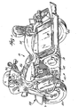
- the illustrated motorcycle 10 includes a drive assembly 12, a frame 14, a front fork assembly 16, a rear fork assembly or swing arm 18, a front wheel 20, a rear wheel 22, a seat 24 and a fuel tank 26.
- the frame 14 supports the drive assembly 12, the front fork assembly 16, the rear fork assembly 18, the seat 24, and the fuel tank 26.
- the front fork assembly 16 is pivotally supported at a front end 28 of the motorcycle 10 and supports the front wheel 20.
- the front fork assembly 16 includes a pair of handle bars 30 for steering the motorcycle 10.
- the rear fork assembly 18 is coupled to the frame 14 at a rear end of the motorcycle 10 and rotatably supports the rear wheel 22.
- the seat 24 is coupled to the frame 14 and is configured for supporting a rider.
- the fuel tank 26 is supported by the frame 14 and provides fuel to the drive assembly 12.
- the drive assembly 12 is preferably coupled to the frame 14 beneath the seat 24 between the front wheel 20 and the rear wheel 22 of the motorcycle 10.
- the drive assembly 12 generally includes an engine 34, a transmission 36, a primary chain 38, a secondary drive belt 40 and a primary drive housing 42.
- the engine 34 and the transmission 36 comprise distinct, independent components of the drive assembly 12 that are supported adjacent one another along an interface 48.
- the engine 34 preferably comprises a V-twin engine supported by the frame 14 forward of the transmission 36.
- the engine 34 includes a conventionally known output shaft 44 (Fig. 8), such as a crankshaft, which includes a primary drive sprocket 45 for driving the primary chain 38 in a conventional manner to power the transmission 36.
- the transmission 36 includes an input shaft 46.
- the input shaft 46 is longitudinally spaced from the output shaft 44 and the centerline 46a of the input shaft extends generally parallel to the centerline 44a of the output shaft 44.
- the input shaft 46 includes a primary driven sprocket 47 supported in engagement with the primary chain 38.
- the primary chain 38 interconnects the output shaft 44 of the engine 34 to the input shaft 46 of the transmission 36 to transmit power from the engine 34 to the transmission 36.
- a secondary drive sprocket 49 is mounted for rotation about a secondary drive shaft 50 having a centerline that is substantially collinear with the centerline 46a of the input shaft 46.
- the transmission 36 drives the secondary drive sprocket 49 through a series of transmission gears (not shown).
- the secondary drive sprocket 49 is driven by the secondary drive shaft 50 and in turn drives the secondary drive belt 40 to drive the rear wheel 22 of the motorcycle 10.
- the motorcycle 10 is illustrated as including the primary chain 38 and the secondary drive belt 40 for transmitting power from the engine 34 to the transmission 36 and for transmitting power from the transmission 36 to the rear wheel 22, respectively, various other power transfer arrangements may alternatively be used.
- the sprockets used in conjunction with the primary chain 38 may be replaced with pulleys and belts.
- the secondary drive belt 40 may be replaced with a sprocket-chain arrangement.
- the output shaft 44 and the input shaft 46 both preferably extend from a left side of the drive assembly 12. Consequently, the drive assembly 12 of the motorcycle 10 complies with and maintains the traditional style and heritage of a motorcycle having a left side drive train. As is also traditional, the left side drive train, including the output shaft 44, the input shaft 46, and the primary chain 38, is enclosed by the primary drive housing 42 on the left side of the motorcycle 10.
- the primary drive housing 42 is a generally hollow enclosure extending between and fixedly coupled to the engine 34 and the transmission 36 on a left side of the motorcycle 10.
- the primary drive housing 42 encloses and shields the output shaft 44, input shaft 46 and primary chain 38.
- the primary drive housing 42 assists in rigidly supporting the engine 34 relative to the transmission 36.
- Fig. 2 is a perspective view illustrating a right side of the drive assembly 12 in greater detail. For ease of illustration, several components of the drive assembly 12 are omitted.
- the engine 34 and the transmission 36 are housed and enclosed by a crankcase 52 and a transmission case 54, respectively.
- the crankcase 52 is a generally rigid enclosure surrounding a lower end of the engine 34 and includes an interface portion 58.
- the transmission case 54 is a generally rigid enclosure enclosing the transmission 36 and includes an interface portion 60.
- the interface portion 58 preferably projects away from the crankcase 52 towards the transmission case 54, and defines a substantially non-horizontal mounting surface for butting against or interconnecting with the interface portion 60 of the transmission case 54.
- the interface portion 60 preferably projects away from the transmission case 54, and defines a non-horizontal mounting surface 64 (shown in Fig. 3) for butting against or interconnecting with the non-horizontal mounting surface of the interface portion 58.
- the interface portions 58, 60 may directly abut each other, or may be interconnected with a gasket or other suitable sealing member between them.
- the interface portions 58 and 60 are rigidly secured adjacent one another by non-vertical (e.g., substantially horizontal) connectors 66 and washers 67 (Figs. 2 and 8).
- the connectors 66 comprise elongated bolts extending through the interface portion 60 and threaded into the interface portion 58.
- the interface portions 58 and 60 may be supported adjacent to one another by a variety of other well known connectors. Because interface portions 58 and 60 are interconnected along substantially non-horizontal mounting surfaces and because the interface portions 58 and 60 are coupled to one another by non-vertical connectors 66, the interface 48 of the crankcase 52 and the transmission case 54 is stiffer and less susceptible to misalignment caused by shear loads.
- the primary drive housing 42 connected between the crankcase 52 and the transmission case 54 experiences smaller loads.
- the interface portions 58 and 60 are interconnected along substantially non-horizontal surfaces, the interface portions 58 and 60 enable the crankcase 52 and the transmission case 54 to be more easily and accurately aligned relative to one another.
- the drive assembly 12 additionally includes an oil reservoir system 70 for housing lubricating fluid for lubricating the engine 34.
- the oil reservoir system 70 generally includes an oil pan 72, oil passages 74 and 76 (shown in Figs. 3-7) and oil conduits 78 and 80.
- the oil pan 72 is supported below the transmission case 54 and is configured for containing oil while the oil is de-aerated and cooled.
- a pump (not shown) pumps the oil through the oil passage 76 and through the oil conduit 80 to the engine 34 for lubricating the engine 34. Oil is returned from the engine 34 to the oil reservoir system 70 for cooling and de-aeration through the oil conduit 78 and through the oil passage 74 (shown in Fig. 3).
- the cavity 81 receives and partially surrounds the oil conduits 78 and 80 to protect the oil conduits 78 and 80 as well as to recess the conduits 78 and 80 at least partially within the drive assembly 12.
- the oil conduits 78 and 80 may be completely covered and hidden from view with a simple cover 81a (Figs. 2 and 4) extending over the conduits 78 and 80, thereby creating a more pleasing aesthetic appearance.
- the cover 81a is fastened to the engine 34 and transmission 54 with fasteners 81b.
- the interface portion 60 preferably includes a pair of legs 82 and 84 and a cross member 86.
- the legs 82 and 84 are vertically spaced from one another at the upper and lower ends of the transmission case 54. Referring to Fig. 2, the legs 82 and 84 extend both vertically and laterally beyond a main body 88 of the transmission case 54.
- the leg 82 includes an upper edge portion 89 extending upwardly beyond the main body 88.
- the lower leg 84 includes a lower edge portion 90 ending below the main body 88.
- the legs 82 and 84 each additionally include opposite ends 92, 93 which laterally project beyond the main body 88.
- each leg 82 and 84 defines a bore 94 at opposite ends for receiving the connectors 66. Because the legs 82 and 84 project vertically and laterally beyond the main body 88 of the transmission case 54, the legs 82 and 84 provide a larger non-horizontal mounting surface to interconnect with the interface portion 58 of the crankcase 52. As a result, the legs 82 and 84 increase the overall stiffness of the interface between the crankcase 52 and the transmission case 54.
- the cross member 86 extends between the legs 82 and 84 intermediate the opposite ends thereof.
- the cross member 86 at least partially defines the passages 74 and 76 for the transmission of oil.
- the cross member 86 and the legs 82 and 84 are configured to provide the interface portion 60 with a general I-shaped cross-section.
- the preferred I-shaped configuration formed at the junction of the interface portions 58 and 60 increases the stiffness and load bearing capability of the drive assembly 12 and provides a reliable, compact circulation pathway for oil between the oil reservoir system 70 (shown in Fig. 2) and the engine 34.
- the interface portion 58 of the crankcase 52 is substantially identical in shape to the interface portion 60 except that the cross member of the interface portion 58 does not define the oil passages 74 and 76.
- Figs. 4-7 illustrate the oil passages 74, 76 and the oil conduits 78, 80 in greater detail.
- the oil passage 74 is a generally hollow passageway extending from the cavity 81 to an interior of the oil reservoir system 70 through the cross member 86.
- the oil passage 74 preferably perpendicularly extends into the cross member 86.
- the oil passage 74 further extends downwardly so as to fluidly communicate with the interior of the reservoir defined by the oil pan 72.
- the oil passage 74 is preferably cast into the transmission case 54.
- the oil passage 74 may be formed by drilling or boring.
- the oil passage 74 may additionally be provided with a lining such as an inner coating applied to inner walls thereof or a tube may be inserted through the oil passage 74.
- the oil passage 74 is illustrated as extending through an L-shaped path through the cross member 86, the oil passage 74 may have a variety of other shapes and may extend through a variety of alternative portions of the transmission case 54 so as to provide fluid communication between the engine 34 and the oil reservoir system 70.
- the oil conduit 78 fluidly connects the oil passage 74 and the interior of the engine 34.
- the oil conduit 78 preferably includes fluid couplings 96, 97, a hose 98 and clamps 99, 100.
- the fluid coupling 96 is conventionally known and generally includes a first end which is threaded into the oil passage 74 and a second end which is fitted within the hose 98.
- the clamp 99 extends about the hose 98 and further seals the hose 98 to the fluid coupling 96.
- the fluid coupling 97 is identical to the fluid coupling 96 except that the fluid coupling 97 is threaded into the bore 101 extending through the crankcase 52 to communicate with the engine 34.
- the fluid coupling 97 further includes a second end fitted within the hose 98.
- the clamp 100 extends about the hose 98 and about the second end of the fluid coupling 97 to sealingly secure the hose 98 about the fluid coupling 97.
- oil from the engine 34 flows through the bore 101 through the fluid coupling 97, the hose 98 and the fluid coupling 96 into the oil passage 74.
- the oil flows through the oil passage 74 formed within the transmission case 54 into the oil pan 72 for de-aeration and cooling.
- fluid conduit 78 is illustrated as a hose with couplings at each end, the fluid conduit 78 may alternatively comprise any one of a variety of fluid conduits such as metal or elastomeric tubes. Furthermore, in lieu of merely extending through and within the cavity 81, the fluid conduit 78 may additionally extend through and within the fluid passage 74 to the oil reservoir system 70.
- the oil passage 76 and the oil conduit 80 direct the oil from the oil reservoir system 70 back to the engine 34.
- the oil passage 76 is a generally hollow passageway extending diagonally upward from the interior of the oil reservoir system 70. As shown in Fig. 6, the oil passage 76 then laterally turns towards the cavity 81 for connection with the oil conduit 80.
- the oil passage 76 is preferably cast as part of the transmission case 54. Alternatively, the oil passage 76 may be formed by boring or drilling into the transmission case 54. The oil passage 76 may additionally be provided with a lining such as an inner coating applied to inner walls of the oil passage 76 or a fluid tube inserted through the oil passage 76. Although the oil passage 76 is illustrated as extending through a generally L-shaped path through the cross member 86 of the interface portion 60, the oil passage 76 may have a variety of other shapes and may extend through various other portions of the transmission case 54 so as to provide fluid communication between the oil reservoir system 70 and the engine 34.
- the oil passage 76 fluidly connects the oil conduit 80 and the interior of the engine 34.
- the oil conduit 80 includes fluid couplings 102 and 104, a hose 106 and clamps 108, 109.
- the fluid coupling 102 is conventionally known and generally includes a first end which is threaded into the oil passage 76 and a second end which is fitted within the hose 106.
- the oil conduit 98 and the oil conduit 106 are identical and interchangeable parts.
- the clamp 108 extends about the hose 106 and further seals the hose 106 to the fluid coupling 102.
- the fluid coupling 104 is identical to the fluid coupling 102 except that the fluid coupling 104 is threaded into the bore 110 extending through the crankcase 52 to communicate with the engine 34.
- the fluid coupling 104 is further fitted within the hose 106.
- the clamp 109 extends about the hose 106 and about an end of the fluid coupling 104 to sealingly secure the hose 106 about the fluid coupling 104.
- oil flows from the oil reservoir system 70 through the oil passage 76, the oil conduit 80 and the bore 110 to the engine 34 for the lubricating engine 34.
- the fluid conduit 80 is illustrated as a hose with couplings at each end, the fluid conduit 80 may alternatively comprise any one of a variety of fluid conduits such as metal or elastomeric tubes. Furthermore, in lieu of merely extending through and within the cavity 81, the fluid conduit 80 may additionally extend through and within the fluid passage 76 to the oil reservoir system 70.
- the interface portions 58 and 60 of the crankcase 52 and the transmission case 54 provide a stiff and easily-aligned junction between the crankcase 52 and the transmission case 54. Because the interface portions 58 and 60 are interconnected along non-horizontal mounting surfaces and because the interface portions 58 and 60 are coupled to one another by non-vertical connectors 66, the interface of the crankcase 52 and the transmission case 54 is stiffer and less susceptible to misalignment caused by shear loads. Consequently, the primary drive housing 42 connected between the crankcase 52 and the transmission case 54 experiences smaller loads.
- the interface portions 58 and 60 also provide more reliable, effective, inconspicuous and aesthetically pleasing oil circulation between the oil reservoir system 70 and the engine 34. Because the cavity 81 of the interface portions 58 and 60 recesses the oil conduits 78 and 80, the oil conduits 78 and 80 are inconspicuously housed and protected. Because the oil passages 74 and 76 lie within the transmission case 54, lengthy hoses which require critical space, which are prone to failure and which are aesthetically unattractive, are eliminated.
- the interface portions 58 and 60 improve upon both the performance and the aesthetic appearance of the motorcycle, while permitting the traditional overall appearance of the motorcycle to be sustained.
Landscapes
- Engineering & Computer Science (AREA)
- General Engineering & Computer Science (AREA)
- Mechanical Engineering (AREA)
- Chemical & Material Sciences (AREA)
- Combustion & Propulsion (AREA)
- Transportation (AREA)
- General Details Of Gearings (AREA)
- Lubrication Of Internal Combustion Engines (AREA)
- Automatic Cycles, And Cycles In General (AREA)
- Lubrication Details And Ventilation Of Internal Combustion Engines (AREA)
- Arrangement Of Transmissions (AREA)
Description
- The present invention relates to motorcycle drive assemblies. In particular, the present invention relates to transmission-to-engine mountings for motorcycle engines.
- Motorcycles are widely used for transportation and recreation. Motorcycles are typically powered by a drive assembly including an engine for generating power and a transmission for adjusting torque and speed. In one well-known motorcycle, the drive assembly comprises a left side drive layout wherein the engine includes a crankshaft or output shaft substantially parallel to an input shaft of the transmission. Power from the engine is transmitted to the transmission with a primary belt or chain interconnecting the parallel output and input shafts of the engine and transmission, respectively. The well-known drive assembly additionally includes a primary drive housing for enclosing the primary belt or chain interconnecting the parallel output and input shafts.
- Over time, this left side drive layout has become one of several characteristic features that motorcycle enthusiasts identify as representative of quality and craftsmanship. Maintaining these characteristic features in new motorcycle designs is desirable to preserve the heritage of this popular motorcycle design. However, in many cases, these characteristic features demanded by motorcycle enthusiasts present obstacles to further development of the motorcycle. Thus, the challenge posed by these obstacles has been to improve the performance of the motorcycle while maintaining the traditional visual aspects of the motorcycle.
- In this well-known motorcycle drive assembly, the engine and the transmission are typically mounted together by means of generally flat horizontal cantilevered pads that overlap one another at a rear of the engine crankcase and at a front of the transmission case. The two horizontal pads are typically held together by two vertical screws. To maintain proper alignment between the engine and the transmission, the primary housing extends across and bolts to the left sides of both the engine crankcase and the transmission case.
- The lubrication system of the drive assembly typically comprises an oil pan, an oil return hose and an oil intake hose. The oil pan acts as a reservoir and contains oil while the oil is de-aerated and cooled. To provide the drive assembly with a compact configuration, the oil pan can be mounted remote or separately from the engine adjacent and below the transmission case. Unfortunately, due to the oil pan's positioning adjacent to the transmission case, the lubrication system requires lengthy hoses extending from the oil reservoir to the engine for providing oil to, and receiving oil from, the engine. These lengthy hoses require critical space, are prone to failure, and can be aesthetically unattractive.
Of theJapanese Patent Application JP 4307161 a - Document
DE 1225061 discloses a motorcycle according to the preamble of claim 1. - The object of the invention is solved by the subject matter of the independent claim 1.
- The transmission of power from the output shaft of the engine to the input shaft of the transmission across the belt or chain generates large loads and a large amount of torque. Because the crankcase of the engine and the transmission case of the transmission are held together by two vertical screws, which react to shear loads at the interface of the crankcase and the transmission case, the interface acts like a hinge. As a result, the primary housing extending across and interconnecting the engine crankcase and the transmission case experiences high loads. The high loads can create misalignment between the engine and the transmission.
- There is a continuing need for a compact, stiffer drive assembly that reduces the loads placed upon the primary drive housing and which more effectively circulates oil between the oil reservoir and the engine.
- The present invention provides an improved motorcycle drive assembly that satisfies one or more of these needs. In one aspect of the invention, the drive assembly includes an engine having an output shaft, and a transmission having an input shaft substantially parallel to the output shaft and coupled to the output shaft (e.g., by a chain or belt). The engine additionally includes a crankcase having a first interface portion with a first non-horizontal (e.g., substantially vertical) mounting surface. The transmission additionally includes a transmission case having a second interface portion with a second non-horizontal (e.g., substantially vertical) mounting surface butting against or interconnected with the first non-horizontal mounting surface to achieve improved alignment and stability. Preferably, the mounting surfaces are substantially I-shaped to further enhance the engine-transmission interface.
- In another aspect of the present invention, the crankcase and the transmission case define a cavity therebetween for housing at least one oil conduit that provides oil flow between the engine and the oil reservoir. Preferably, there are two conduits: one providing oil flow to the engine and one providing oil flow away from the engine.
- In another aspect of the present invention, the drive assembly includes an oil reservoir adjacent to the transmission case. The second interface portion of the transmission case at least partially defines at least one oil passage in fluid communication with the oil reservoir.
-
- Fig. 1 is a perspective view of a motorcycle including a drive assembly embodying the present invention.
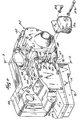
- Fig. 2 is a perspective view illustrating a crankcase, a transmission case, a primary housing and a lubrication system of the drive assembly.
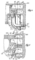
- Fig. 3 is a sectional view of the drive assembly taken along
lines 3--3 of Fig. 2 at the interface between the crankcase and the transmission case and with the oil conduit cover removed. - Fig. 4 is a fragmentary sectional view of the drive assembly taken along lines 4--4 of Fig. 3.
- Fig. 5 is a fragmentary sectional view of the drive assembly taken along
lines 5--5 of Fig. 3. - Fig. 6 is a fragmentary sectional view of the drive assembly taken along lines 6--6 of Fig. 3.
- Fig. 7 is a fragmentary sectional view of the drive assembly taken along lines 7--7 of Fig. 3.
- Fig. 8 is a partial section top view of the drive assembly.
- The illustrated motorcycle 10 includes a
drive assembly 12, a frame 14, a front fork assembly 16, a rear fork assembly orswing arm 18, a front wheel 20, a rear wheel 22, aseat 24 and afuel tank 26. As conventionally known, the frame 14 supports thedrive assembly 12, the front fork assembly 16, therear fork assembly 18, theseat 24, and thefuel tank 26. The front fork assembly 16 is pivotally supported at afront end 28 of the motorcycle 10 and supports the front wheel 20. The front fork assembly 16 includes a pair ofhandle bars 30 for steering the motorcycle 10. Therear fork assembly 18 is coupled to the frame 14 at a rear end of the motorcycle 10 and rotatably supports the rear wheel 22. Theseat 24 is coupled to the frame 14 and is configured for supporting a rider. Thefuel tank 26 is supported by the frame 14 and provides fuel to thedrive assembly 12. - The
drive assembly 12 is preferably coupled to the frame 14 beneath theseat 24 between the front wheel 20 and the rear wheel 22 of the motorcycle 10. Referring to Figs. 1 and 8, thedrive assembly 12 generally includes anengine 34, atransmission 36, aprimary chain 38, asecondary drive belt 40 and aprimary drive housing 42. As shown in Fig. 2, theengine 34 and thetransmission 36 comprise distinct, independent components of thedrive assembly 12 that are supported adjacent one another along aninterface 48. Theengine 34 preferably comprises a V-twin engine supported by the frame 14 forward of thetransmission 36. Theengine 34 includes a conventionally known output shaft 44 (Fig. 8), such as a crankshaft, which includes a primary drive sprocket 45 for driving theprimary chain 38 in a conventional manner to power thetransmission 36. - Referring to Figs. 1, 2, and 8, the
transmission 36 includes aninput shaft 46. Theinput shaft 46 is longitudinally spaced from theoutput shaft 44 and thecenterline 46a of the input shaft extends generally parallel to the centerline 44a of theoutput shaft 44. Theinput shaft 46 includes a primary drivensprocket 47 supported in engagement with theprimary chain 38. Theprimary chain 38 interconnects theoutput shaft 44 of theengine 34 to theinput shaft 46 of thetransmission 36 to transmit power from theengine 34 to thetransmission 36. A secondary drive sprocket 49 is mounted for rotation about a secondary drive shaft 50 having a centerline that is substantially collinear with thecenterline 46a of theinput shaft 46. - The
transmission 36 drives the secondary drive sprocket 49 through a series of transmission gears (not shown). The secondary drive sprocket 49 is driven by the secondary drive shaft 50 and in turn drives thesecondary drive belt 40 to drive the rear wheel 22 of the motorcycle 10. Although the motorcycle 10 is illustrated as including theprimary chain 38 and thesecondary drive belt 40 for transmitting power from theengine 34 to thetransmission 36 and for transmitting power from thetransmission 36 to the rear wheel 22, respectively, various other power transfer arrangements may alternatively be used. For example, the sprockets used in conjunction with theprimary chain 38 may be replaced with pulleys and belts. Similarly, thesecondary drive belt 40 may be replaced with a sprocket-chain arrangement. - As shown in Figs. 1 and 8, the
output shaft 44 and theinput shaft 46 both preferably extend from a left side of thedrive assembly 12. Consequently, thedrive assembly 12 of the motorcycle 10 complies with and maintains the traditional style and heritage of a motorcycle having a left side drive train. As is also traditional, the left side drive train, including theoutput shaft 44, theinput shaft 46, and theprimary chain 38, is enclosed by theprimary drive housing 42 on the left side of the motorcycle 10. - The
primary drive housing 42 is a generally hollow enclosure extending between and fixedly coupled to theengine 34 and thetransmission 36 on a left side of the motorcycle 10. Theprimary drive housing 42 encloses and shields theoutput shaft 44,input shaft 46 andprimary chain 38. In addition, theprimary drive housing 42 assists in rigidly supporting theengine 34 relative to thetransmission 36. - Fig. 2 is a perspective view illustrating a right side of the
drive assembly 12 in greater detail. For ease of illustration, several components of thedrive assembly 12 are omitted. As shown in Fig. 2, theengine 34 and thetransmission 36 are housed and enclosed by acrankcase 52 and atransmission case 54, respectively. Thecrankcase 52 is a generally rigid enclosure surrounding a lower end of theengine 34 and includes aninterface portion 58. Similarly, thetransmission case 54 is a generally rigid enclosure enclosing thetransmission 36 and includes aninterface portion 60. - The
interface portion 58 preferably projects away from thecrankcase 52 towards thetransmission case 54, and defines a substantially non-horizontal mounting surface for butting against or interconnecting with theinterface portion 60 of thetransmission case 54. Likewise, theinterface portion 60 preferably projects away from thetransmission case 54, and defines a non-horizontal mounting surface 64 (shown in Fig. 3) for butting against or interconnecting with the non-horizontal mounting surface of theinterface portion 58. Theinterface portions - The
interface portions connectors 66 and washers 67 (Figs. 2 and 8). In the illustrated embodiment, theconnectors 66 comprise elongated bolts extending through theinterface portion 60 and threaded into theinterface portion 58. Alternatively, theinterface portions interface portions interface portions non-vertical connectors 66, theinterface 48 of thecrankcase 52 and thetransmission case 54 is stiffer and less susceptible to misalignment caused by shear loads. As a result, theprimary drive housing 42 connected between thecrankcase 52 and thetransmission case 54 experiences smaller loads. In addition, because theinterface portions interface portions crankcase 52 and thetransmission case 54 to be more easily and accurately aligned relative to one another. - As shown in Fig. 2, the
drive assembly 12 additionally includes anoil reservoir system 70 for housing lubricating fluid for lubricating theengine 34. Theoil reservoir system 70 generally includes anoil pan 72,oil passages 74 and 76 (shown in Figs. 3-7) andoil conduits oil pan 72 is supported below thetransmission case 54 and is configured for containing oil while the oil is de-aerated and cooled. Once the oil is de-aerated and cooled, a pump (not shown) pumps the oil through theoil passage 76 and through theoil conduit 80 to theengine 34 for lubricating theengine 34. Oil is returned from theengine 34 to theoil reservoir system 70 for cooling and de-aeration through theoil conduit 78 and through the oil passage 74 (shown in Fig. 3). - As shown in Figs. 2-4 and 6, the
interface portions crankcase 52 andtransmission 54, define acavity 81. Thecavity 81 receives and partially surrounds theoil conduits oil conduits conduits drive assembly 12. As a result, theoil conduits simple cover 81a (Figs. 2 and 4) extending over theconduits cover 81a is fastened to theengine 34 andtransmission 54 with fasteners 81b. - As best shown in Fig. 3, the
interface portion 60 preferably includes a pair oflegs cross member 86. Thelegs transmission case 54. Referring to Fig. 2, thelegs main body 88 of thetransmission case 54. In particular, theleg 82 includes anupper edge portion 89 extending upwardly beyond themain body 88. Thelower leg 84 includes alower edge portion 90 ending below themain body 88. Thelegs main body 88. The ends 92 and 93 are mounted to theinterface portion 58 of the crankcase 52 (shown in Fig. 2) by theconnectors 66 and washers 67 (Fig. 2). In the illustrated embodiment, eachleg bore 94 at opposite ends for receiving theconnectors 66. Because thelegs main body 88 of thetransmission case 54, thelegs interface portion 58 of thecrankcase 52. As a result, thelegs crankcase 52 and thetransmission case 54. Because the ends 92 and 93 of thelegs connector 66 laterally beyond themain body 88 of thetransmission case 54, theconnectors 66 are more easily accessed for easier assembly and disassembly. Thecross member 86 extends between thelegs cross member 86 at least partially defines thepassages - In the illustrated embodiment, the
cross member 86 and thelegs interface portion 60 with a general I-shaped cross-section. The preferred I-shaped configuration formed at the junction of theinterface portions drive assembly 12 and provides a reliable, compact circulation pathway for oil between the oil reservoir system 70 (shown in Fig. 2) and theengine 34. Although not shown in detail, theinterface portion 58 of thecrankcase 52 is substantially identical in shape to theinterface portion 60 except that the cross member of theinterface portion 58 does not define theoil passages - Figs. 4-7 illustrate the
oil passages oil conduits oil passage 74 is a generally hollow passageway extending from thecavity 81 to an interior of theoil reservoir system 70 through thecross member 86. As shown in Fig. 4, theoil passage 74 preferably perpendicularly extends into thecross member 86. As best shown in Fig. 5, theoil passage 74 further extends downwardly so as to fluidly communicate with the interior of the reservoir defined by theoil pan 72. - The
oil passage 74 is preferably cast into thetransmission case 54. Alternatively, theoil passage 74 may be formed by drilling or boring. Theoil passage 74 may additionally be provided with a lining such as an inner coating applied to inner walls thereof or a tube may be inserted through theoil passage 74. Although theoil passage 74 is illustrated as extending through an L-shaped path through thecross member 86, theoil passage 74 may have a variety of other shapes and may extend through a variety of alternative portions of thetransmission case 54 so as to provide fluid communication between theengine 34 and theoil reservoir system 70. - The
oil conduit 78 fluidly connects theoil passage 74 and the interior of theengine 34. Theoil conduit 78 preferably includes fluid couplings 96, 97, ahose 98 and clamps 99, 100. The fluid coupling 96 is conventionally known and generally includes a first end which is threaded into theoil passage 74 and a second end which is fitted within thehose 98. Theclamp 99 extends about thehose 98 and further seals thehose 98 to the fluid coupling 96. - The fluid coupling 97 is identical to the fluid coupling 96 except that the fluid coupling 97 is threaded into the
bore 101 extending through thecrankcase 52 to communicate with theengine 34. The fluid coupling 97 further includes a second end fitted within thehose 98. Theclamp 100 extends about thehose 98 and about the second end of the fluid coupling 97 to sealingly secure thehose 98 about the fluid coupling 97. As indicated by the arrows A, oil from theengine 34 flows through thebore 101 through the fluid coupling 97, thehose 98 and the fluid coupling 96 into theoil passage 74. The oil flows through theoil passage 74 formed within thetransmission case 54 into theoil pan 72 for de-aeration and cooling. - Although the
fluid conduit 78 is illustrated as a hose with couplings at each end, thefluid conduit 78 may alternatively comprise any one of a variety of fluid conduits such as metal or elastomeric tubes. Furthermore, in lieu of merely extending through and within thecavity 81, thefluid conduit 78 may additionally extend through and within thefluid passage 74 to theoil reservoir system 70. - Once the oil has been cooled and de-aerated within the
oil pan 72, the oil must be returned to theengine 34 to further lubricate theengine 34. Theoil passage 76 and theoil conduit 80 direct the oil from theoil reservoir system 70 back to theengine 34. As best shown in Fig. 7, theoil passage 76 is a generally hollow passageway extending diagonally upward from the interior of theoil reservoir system 70. As shown in Fig. 6, theoil passage 76 then laterally turns towards thecavity 81 for connection with theoil conduit 80. - The
oil passage 76 is preferably cast as part of thetransmission case 54. Alternatively, theoil passage 76 may be formed by boring or drilling into thetransmission case 54. Theoil passage 76 may additionally be provided with a lining such as an inner coating applied to inner walls of theoil passage 76 or a fluid tube inserted through theoil passage 76. Although theoil passage 76 is illustrated as extending through a generally L-shaped path through thecross member 86 of theinterface portion 60, theoil passage 76 may have a variety of other shapes and may extend through various other portions of thetransmission case 54 so as to provide fluid communication between theoil reservoir system 70 and theengine 34. - The
oil passage 76 fluidly connects theoil conduit 80 and the interior of theengine 34. In the illustrated embodiment, theoil conduit 80 includesfluid couplings hose 106 and clamps 108, 109. Thefluid coupling 102 is conventionally known and generally includes a first end which is threaded into theoil passage 76 and a second end which is fitted within thehose 106. Theoil conduit 98 and theoil conduit 106 are identical and interchangeable parts. Theclamp 108 extends about thehose 106 and further seals thehose 106 to thefluid coupling 102. - The
fluid coupling 104 is identical to thefluid coupling 102 except that thefluid coupling 104 is threaded into thebore 110 extending through thecrankcase 52 to communicate with theengine 34. Thefluid coupling 104 is further fitted within thehose 106. Theclamp 109 extends about thehose 106 and about an end of thefluid coupling 104 to sealingly secure thehose 106 about thefluid coupling 104. As indicated by arrows B, oil flows from theoil reservoir system 70 through theoil passage 76, theoil conduit 80 and thebore 110 to theengine 34 for thelubricating engine 34. - Although the
fluid conduit 80 is illustrated as a hose with couplings at each end, thefluid conduit 80 may alternatively comprise any one of a variety of fluid conduits such as metal or elastomeric tubes. Furthermore, in lieu of merely extending through and within thecavity 81, thefluid conduit 80 may additionally extend through and within thefluid passage 76 to theoil reservoir system 70. - In conclusion, the
interface portions crankcase 52 and thetransmission case 54, respectively, provide a stiff and easily-aligned junction between thecrankcase 52 and thetransmission case 54. Because theinterface portions interface portions non-vertical connectors 66, the interface of thecrankcase 52 and thetransmission case 54 is stiffer and less susceptible to misalignment caused by shear loads. Consequently, theprimary drive housing 42 connected between thecrankcase 52 and thetransmission case 54 experiences smaller loads. - In addition, the
interface portions oil reservoir system 70 and theengine 34. Because thecavity 81 of theinterface portions oil conduits oil conduits oil passages transmission case 54, lengthy hoses which require critical space, which are prone to failure and which are aesthetically unattractive, are eliminated. - As a result, the
interface portions - Although particular embodiments of the present invention have been shown and described, other alternative embodiments will be apparent to those skilled in the art and are within the intended scope of the present invention. Thus, the present invention is to be limited only by the following claims.
Claims (14)
- A motorcycle (10) comprising:a front wheel(28);a rear wheel(22);a frame (14) supported by said front wheel(28) and said rear wheel(22);an engine (34) supported by said frame (14) and having a first interface portion (58); anda transmission (36) supported by said frame (14) and having a second interface (60) portion engaged with said first interface portion (58) along a non-horizontalinterface (48) characterized in that said first and second interface portions (58, 60) together define a side cavity (81), said side cavity (81) at least partially housing an oil conduit (78; 80).
- The motorcycle (10) of claim 1, further comprising:an engine output shaft (44) supported for rotation within said engine (34); anda transmission input shaft (46) mounted for rotation within said transmission (36), said input shaft (46) being substantially parallel to and coupled to said output shaft (44).
- The motorcycle (10) of claim 1, wherein said first and second interface portions (58; 60) have !-shaped cross-sections.
- The motorcycle (10) of claim 1, wherein said first interface (58) portion is engaged with said second interface (60) portion along a substantially vertical interface.
- The motorcycle (10) of one of the foregoing claims, wherein said I-shaped cross-section of each of said first and second interface portions (58; 60) includes a top cross member and a bottom cross member, and wherein said motorcycle (10) further includes a plurality of fasteners (66), at least one said fastener being positioned at opposite ends of each of said top cross members and at each of opposite ends of each of said bottom cross members.
- The motorcycle (10) according to one of the foregoing claims, with the first interface portion (58) having an outer surface;
the second interface portion (60) having an outer surface, said second interface portion being engaged with said first interface portion, wherein said outer surface of said first interface portion and said outer surface of said second interface portion together define a side cavity (81); and
the oil conduit (78, 80) positioned within said side cavity (81). - The motorcycle (10) of claim 6, further comprising an oil reservoir (70) in fluid communication with said engine (34) through said oil conduit (78, 80).
- The motorcycle(10) of claim 7, wherein said oil reservoir (70) is at least partially defined by an oil pan (72) mounted below said transmission (36).
- The motorcycle (10) of one of claims 7 or 8, wherein said oil conduit (78, 80) includes a first conduit (78) and a second conduit (80), said first conduit (78) allowing oil to flow from said engine (34) to said oil reservoir (70), said second conduit (80) allowing oil to flow from said oil reservoir (70) to said engine (34).
- The motorcycle (10) of one of the foregoing claims, wherein said oil conduit (78, 80) bends substantially 90°.
- The motorcycle(10) of one of the foregoing claims, further comprising an oil passage (74, 76) within in said transmission (36) that is in communication with said oil conduit (78, 80).
- The motorcycle (10) according to one of the foregoing claims, comprising a transmission case (54) as part of the transmission (36) supported by said frame (12) and including the second interface portion (60) engaged with said first interface portion (58), wherein said transmission case (54) at least partially defines the oil passage (74, 76) for routing engine oil between said oil reservoir (70) and said engine (34).
- The motorcycle(10) of claim11 or 12, wherein said passage (74, 76) includes a first oil passage (74) and a second oil passage (76).
- The motorcycle (10) of claim 13, wherein said first oil passage (76) routes oil from said oil reservoir (70) to said engine (34), said second oil passage (74) routes oil from said engine (34) to said oil reservoir (70).
Priority Applications (1)
| Application Number | Priority Date | Filing Date | Title |
|---|---|---|---|
| EP07014722A EP1884459A3 (en) | 1998-06-30 | 1999-06-21 | Motorcycle drive assembly with improved transmission-to-engine mounting |
Applications Claiming Priority (4)
| Application Number | Priority Date | Filing Date | Title |
|---|---|---|---|
| US122007 | 1993-09-15 | ||
| US9122898P | 1998-06-30 | 1998-06-30 | |
| US91228P | 1998-06-30 | ||
| US09/122,007 US6085855A (en) | 1998-06-30 | 1998-07-24 | Motorcycle drive assembly with improved transmission-to-engine mounting |
Related Child Applications (1)
| Application Number | Title | Priority Date | Filing Date |
|---|---|---|---|
| EP07014722A Division EP1884459A3 (en) | 1998-06-30 | 1999-06-21 | Motorcycle drive assembly with improved transmission-to-engine mounting |
Publications (3)
| Publication Number | Publication Date |
|---|---|
| EP0968910A2 EP0968910A2 (en) | 2000-01-05 |
| EP0968910A3 EP0968910A3 (en) | 2000-10-25 |
| EP0968910B1 true EP0968910B1 (en) | 2007-12-19 |
Family
ID=26783739
Family Applications (1)
| Application Number | Title | Priority Date | Filing Date |
|---|---|---|---|
| EP99112004A Expired - Lifetime EP0968910B1 (en) | 1998-06-30 | 1999-06-21 | Motorcycle drive assembly with improved transmission-to-engine mounting |
Country Status (4)
| Country | Link |
|---|---|
| US (2) | US6085855A (en) |
| EP (1) | EP0968910B1 (en) |
| JP (1) | JP2000025673A (en) |
| DE (1) | DE69937772T2 (en) |
Families Citing this family (15)
| Publication number | Priority date | Publication date | Assignee | Title |
|---|---|---|---|---|
| US6085855A (en) * | 1998-06-30 | 2000-07-11 | Harley-Davidson Motor Company | Motorcycle drive assembly with improved transmission-to-engine mounting |
| US6315072B1 (en) * | 1999-07-29 | 2001-11-13 | Harley-Davidson Motor Company Group, Inc. | Motorcycle engine mounting assembly |
| JP4393718B2 (en) * | 2001-01-11 | 2010-01-06 | 本田技研工業株式会社 | V-type internal combustion engine |
| US7299895B2 (en) * | 2003-02-14 | 2007-11-27 | S & S Cycle, Inc. | Engine crankcase |
| US6902023B2 (en) * | 2003-07-11 | 2005-06-07 | Harley-Davidson Motor Company Group, Inc. | Engine mounting system for a motorcycle |
| US6941920B1 (en) | 2004-04-02 | 2005-09-13 | Kenneth R. Thurm | Motorcycle engine and transmission interbracing member |
| US20050252471A1 (en) * | 2004-05-14 | 2005-11-17 | S & S Cycle, Inc. | Twin cylinder motorcycle engine |
| US7096846B1 (en) * | 2005-07-01 | 2006-08-29 | Harley-Davidson Motor Company Group, Inc. | Engine and transmission case assembly |
| USD544509S1 (en) | 2005-09-30 | 2007-06-12 | S&S Cycle, Inc. | Gear cover |
| US7171939B1 (en) | 2005-09-30 | 2007-02-06 | S&S Cycle, Inc. | Integrated cam drive and oil pump assembly for motorcycle engines and the like |
| US20080178832A1 (en) * | 2007-01-25 | 2008-07-31 | R&R Cycles Inc. | Camshaft support and crankcase air vent for an engine |
| US20100037844A1 (en) * | 2008-08-13 | 2010-02-18 | Dan Kinsey | Cylinder head and rocker arm assembly for internal combustion engine |
| JP5195632B2 (en) * | 2009-05-13 | 2013-05-08 | トヨタ自動車株式会社 | Power unit fastening structure |
| US8276693B2 (en) | 2011-02-16 | 2012-10-02 | American Challenge Technologies, Inc. | Powertrain, vehicle, and method with electric motors and dual belt drive |
| JP2016089661A (en) * | 2014-10-31 | 2016-05-23 | ヤマハ発動機株式会社 | Engine and motorcycle with the same |
Family Cites Families (13)
| Publication number | Priority date | Publication date | Assignee | Title |
|---|---|---|---|---|
| DE1213164B (en) * | 1963-10-11 | 1966-03-24 | Mach Agricoles Rotatives Simar | Internal combustion engine with built-in clutch |
| DE1225061B (en) * | 1965-05-22 | 1966-09-15 | Zschopau Motorrad Veb | Rotary piston internal combustion engine with change gear, especially for two-wheeled vehicles |
| US4690236A (en) * | 1982-09-29 | 1987-09-01 | Honda Giken Kogyo Kabushiki Kaisha | Motorcycle lubrication system |
| DE3326321A1 (en) * | 1983-07-21 | 1985-01-31 | Dr.Ing.H.C. F. Porsche Ag, 7000 Stuttgart | INTERNAL COMBUSTION ENGINE |
| JPS6069251A (en) * | 1983-09-26 | 1985-04-19 | Yamaha Motor Co Ltd | Crankcase for multi-cylinder engine |
| JPH0656193B2 (en) * | 1984-07-13 | 1994-07-27 | ヤマハ発動機株式会社 | Internal combustion engine with auxiliary transmission for vehicles |
| CA1249192A (en) * | 1984-09-14 | 1989-01-24 | Munenori Kiryu | Method and apparatus for cooling cylinder head of an engine |
| JP2805758B2 (en) * | 1988-08-01 | 1998-09-30 | スズキ株式会社 | Motorcycle engine crankcase |
| US5070830A (en) * | 1990-07-17 | 1991-12-10 | Saturn Corporation | Powertrain and stiffening bracket therefor |
| DE69404782T2 (en) * | 1993-08-30 | 1997-12-04 | Honda Motor Co Ltd | Oil supply construction for starter gears in an internal combustion engine |
| US5458101A (en) * | 1994-07-11 | 1995-10-17 | Crooks; William A. | Lubricating tank assembly and system for motorcycle engines |
| US5937817A (en) * | 1998-06-23 | 1999-08-17 | Harley-Davidson Motor Company | Dry sump oil cooling system |
| US6085855A (en) * | 1998-06-30 | 2000-07-11 | Harley-Davidson Motor Company | Motorcycle drive assembly with improved transmission-to-engine mounting |
-
1998
- 1998-07-24 US US09/122,007 patent/US6085855A/en not_active Expired - Lifetime
-
1999
- 1999-06-21 EP EP99112004A patent/EP0968910B1/en not_active Expired - Lifetime
- 1999-06-21 DE DE69937772T patent/DE69937772T2/en not_active Expired - Lifetime
- 1999-06-22 JP JP11174796A patent/JP2000025673A/en active Pending
-
2000
- 2000-03-15 US US09/525,387 patent/US6241040B1/en not_active Expired - Lifetime
Also Published As
| Publication number | Publication date |
|---|---|
| EP0968910A3 (en) | 2000-10-25 |
| EP0968910A2 (en) | 2000-01-05 |
| DE69937772T2 (en) | 2008-04-30 |
| US6241040B1 (en) | 2001-06-05 |
| DE69937772D1 (en) | 2008-01-31 |
| US6085855A (en) | 2000-07-11 |
| JP2000025673A (en) | 2000-01-25 |
Similar Documents
| Publication | Publication Date | Title |
|---|---|---|
| US6085855A (en) | Motorcycle drive assembly with improved transmission-to-engine mounting | |
| US7448355B2 (en) | Integrated power unit including split crankcase with reinforced fastening arrangement, and vehicle including same | |
| JP4419446B2 (en) | Engine lubrication structure | |
| US8844493B2 (en) | Lubricating oil feeding structure of engine | |
| AU2013205955B2 (en) | Water cooled internal combustion engine for vehicle | |
| ITMI20061243A1 (en) | ENGINE AND SET OF TRANSMISSION CONTAINER | |
| EP1138886B1 (en) | Lubrication structure for internal combustion engine | |
| US20010023670A1 (en) | Cooling water circulating structure in internal combustion engine | |
| US7516727B2 (en) | Vehicle combustion engine | |
| CN102003263B (en) | Cooling device of a power unit | |
| US6892844B2 (en) | Coolant pump for snowmobile engine | |
| JP5048618B2 (en) | 4-cycle air-oil cooled engine | |
| EP1884459A2 (en) | Motorcycle drive assembly with improved transmission-to-engine mounting | |
| US7147077B2 (en) | Engine starter mechanism arrangement for snow vehicles | |
| US7565891B2 (en) | Engine for vehicle | |
| EP2154340A1 (en) | Internal Combustion Engine | |
| US6631780B1 (en) | Engine with torque converter | |
| US8960684B2 (en) | Internal combustion engine having positioning pins disposed within fluid communication ports | |
| JP3668548B2 (en) | Support structure of balancer shaft in engine | |
| JP3438343B2 (en) | Cover structure of vehicle engine | |
| JP2014080895A (en) | Internal combustion engine | |
| JP4851899B2 (en) | Vehicle engine | |
| JP4718406B2 (en) | Engine lubrication equipment | |
| US7299895B2 (en) | Engine crankcase | |
| JP2010071129A (en) | Structure of engine cooling oil passage |
Legal Events
| Date | Code | Title | Description |
|---|---|---|---|
| PUAI | Public reference made under article 153(3) epc to a published international application that has entered the european phase |
Free format text: ORIGINAL CODE: 0009012 |
|
| AK | Designated contracting states |
Kind code of ref document: A2 Designated state(s): DE GB IT |
|
| AX | Request for extension of the european patent |
Free format text: AL;LT;LV;MK;RO;SI |
|
| PUAL | Search report despatched |
Free format text: ORIGINAL CODE: 0009013 |
|
| AK | Designated contracting states |
Kind code of ref document: A3 Designated state(s): AT BE CH CY DE DK ES FI FR GB GR IE IT LI LU MC NL PT SE |
|
| AX | Request for extension of the european patent |
Free format text: AL;LT;LV;MK;RO;SI |
|
| 17P | Request for examination filed |
Effective date: 20001211 |
|
| AKX | Designation fees paid |
Free format text: DE GB IT |
|
| 17Q | First examination report despatched |
Effective date: 20060807 |
|
| GRAP | Despatch of communication of intention to grant a patent |
Free format text: ORIGINAL CODE: EPIDOSNIGR1 |
|
| GRAS | Grant fee paid |
Free format text: ORIGINAL CODE: EPIDOSNIGR3 |
|
| GRAA | (expected) grant |
Free format text: ORIGINAL CODE: 0009210 |
|
| RAP1 | Party data changed (applicant data changed or rights of an application transferred) |
Owner name: HARLEY-DAVIDSON MOTOR COMPANY GROUP, INC. |
|
| AK | Designated contracting states |
Kind code of ref document: B1 Designated state(s): DE GB IT |
|
| REG | Reference to a national code |
Ref country code: GB Ref legal event code: FG4D |
|
| REF | Corresponds to: |
Ref document number: 69937772 Country of ref document: DE Date of ref document: 20080131 Kind code of ref document: P |
|
| PLBE | No opposition filed within time limit |
Free format text: ORIGINAL CODE: 0009261 |
|
| STAA | Information on the status of an ep patent application or granted ep patent |
Free format text: STATUS: NO OPPOSITION FILED WITHIN TIME LIMIT |
|
| 26N | No opposition filed |
Effective date: 20080922 |
|
| GBPC | Gb: european patent ceased through non-payment of renewal fee |
Effective date: 20080621 |
|
| PG25 | Lapsed in a contracting state [announced via postgrant information from national office to epo] |
Ref country code: GB Free format text: LAPSE BECAUSE OF NON-PAYMENT OF DUE FEES Effective date: 20080621 |
|
| PG25 | Lapsed in a contracting state [announced via postgrant information from national office to epo] |
Ref country code: IT Free format text: LAPSE BECAUSE OF NON-PAYMENT OF DUE FEES Effective date: 20080630 |
|
| PGFP | Annual fee paid to national office [announced via postgrant information from national office to epo] |
Ref country code: DE Payment date: 20110629 Year of fee payment: 13 |
|
| REG | Reference to a national code |
Ref country code: DE Ref legal event code: R119 Ref document number: 69937772 Country of ref document: DE Effective date: 20130101 |
|
| PG25 | Lapsed in a contracting state [announced via postgrant information from national office to epo] |
Ref country code: DE Free format text: LAPSE BECAUSE OF NON-PAYMENT OF DUE FEES Effective date: 20130101 |