EP0967761A1 - Transmission method for digital data via a burst error channel - Google Patents
Transmission method for digital data via a burst error channel Download PDFInfo
- Publication number
- EP0967761A1 EP0967761A1 EP98810582A EP98810582A EP0967761A1 EP 0967761 A1 EP0967761 A1 EP 0967761A1 EP 98810582 A EP98810582 A EP 98810582A EP 98810582 A EP98810582 A EP 98810582A EP 0967761 A1 EP0967761 A1 EP 0967761A1
- Authority
- EP
- European Patent Office
- Prior art keywords
- symbols
- distance
- quality
- window
- characteristic
- Prior art date
- Legal status (The legal status is an assumption and is not a legal conclusion. Google has not performed a legal analysis and makes no representation as to the accuracy of the status listed.)
- Withdrawn
Links
Images


Classifications
-
- H—ELECTRICITY
- H04—ELECTRIC COMMUNICATION TECHNIQUE
- H04B—TRANSMISSION
- H04B3/00—Line transmission systems
- H04B3/02—Details
- H04B3/04—Control of transmission; Equalising
-
- H—ELECTRICITY
- H04—ELECTRIC COMMUNICATION TECHNIQUE
- H04L—TRANSMISSION OF DIGITAL INFORMATION, e.g. TELEGRAPHIC COMMUNICATION
- H04L25/00—Baseband systems
- H04L25/02—Details ; arrangements for supplying electrical power along data transmission lines
- H04L25/06—Dc level restoring means; Bias distortion correction ; Decision circuits providing symbol by symbol detection
- H04L25/067—Dc level restoring means; Bias distortion correction ; Decision circuits providing symbol by symbol detection providing soft decisions, i.e. decisions together with an estimate of reliability
Definitions
- the invention relates to a method for transmitting digital data via a bundled interference occurring transmission channel, being in a receiver after demodulation, a soft-decision decoding taking into account an estimated signal quality is performed.
- the invention further relates to a receiver circuit for performing the method.
- the object of the invention is to provide a method of the type mentioned, which an improved detection in the presence of pulse-like or bundled bursty) provides interference.
- the reception quality is estimated using a circuit whose Characteristic has a hump (or S-line characteristic), which at one lower signal to noise ratio an overvaluation relative to a linear characteristic and with a higher signal to noise ratio relative undervaluation of the signal quality generated.
- hump or S-line characteristic
- the signal quality or the signal to noise ratio is based on the variance of the fault process is estimated within a given window.
- this window has a length in the range of the shortest to be expected Glitches. This ensures that the estimation of the signal quality is sufficient reacts quickly to occurring interference pulse bundles.
- the signal quality is determined for a predetermined number of receivers (according to the window length) Symbols checked whether they are within a predefined distance from one of the existing ones Constellation points. The number of within the specified distance lying symbols is used as a quality value for the subsequent soft-decision decoding used.
- the distance used as a threshold depends on the modulation method, on the statistics of the interference pulses and in individual cases on further parameters.
- the distance can be chosen so that with a ratio of Signal to noise of at least about 5 dB statistically, the majority of the symbols of the respective window within the specified distance to a constellation point lie.
- the hump of the characteristic below should be around 5 dB.
- BPSK Binary Phase Shift Keying
- D 0.5 particularly advantageous. Overall, this value can be the best Achieve system performance. Of course, other values are not fundamental not suitable.
- the implementation of the method according to the invention only affects the recipient out.
- the transmitter circuits can be implemented in a manner known per se.
- the receiver there is between the demodulation stage and the soft decision decoding inserted a module, which according to the described method the symbol quality estimates.
- the estimated quality value is in together with the symbol estimate the subsequent decoding used to determine the symbol transmitted. If the module according to the invention is implemented in software or hardware, is not essential to the invention.
- FEC Forward Error Correction
- the digital data of a data source 4 are encoded in a coder 5 according to a method known per se to symbols, to enable a correction of transmission errors on the receiver side.
- the Modulator 6 carries out a modulation appropriate for transmission channel 2.
- the transmission channel 2 is e.g. through a radio transmission link or through lines an electrical power distribution network. It is assumed, that it is associated with time-variant interferences (interference impulses, interferences, echoes etc.). For the examples below, it is assumed that the shortest expected Interference pulses have a length in the range of 1 ⁇ s (or a little less). In the absence of interference pulses is of an interference-to-noise ratio of at least about 10 dB assumed.
- the received signal in the demodulator 7 (which is also an equalizer demodulated and in the decoder 9 to determine the data sink 10 decoded data to be delivered.
- the decoder 9 is a known one Principles working soft-decision decoder.
- the signal quality estimator is essential to the invention 8, which determines the reliability of the symbols estimated by the demodulator 7 and a corresponding reliability value for soft-decision decoding provides.
- FIG. 2 shows a block diagram of the signal quality estimator 8. It is assumed that that 1 symbols of a predefined constellation are generated in the transmitter. This Symbols are usually transmitted one after the other, but can also be transmitted simultaneously (e.g. with different frequencies) are transmitted. As part of the following explanations a chronological order is assumed.
- the noise process (which can also be based on interference) can occur in the receiver can be considered as random.
- the disturbances are bundled or impulse-like accepted (English bursty). By that is meant that it is an "ordinary” noise performance (Engl. noise power) there and that this noise power from time to time Time for a short period increases to a very high value, afterwards to the "ordinary” Value falling behind. Both the increase and the duration of the increase the noise performance are random.
- the noise power is determined for each symbol transmitted. Without restricting generality, it can be assumed that the signal power is known (e.g. due to a measurement at the beginning of the reception of a data block). What is wanted, however, is not the current performance of the faults, but the Variance of the noise process at a given time.
- the noise power estimate is based on a block or window of N successive symbols.
- the length N of the window becomes the expected one Noise process selected. Larger window lengths result in constant signal quality for greater accuracy, but for a slower response to changes in the signal quality.
- PLC Powerline Communication
- Symbol rate symbols per second
- the noise level determined with the window becomes for that in the center of the window lying icon used. If N is odd, the result of the signal quality estimate depends of (N-1) / 2 previous and of (N-1) / 2 subsequent demodulated Symbols as well as from the symbol, the quality of which must be valued. (The length N can also be straight; but then the estimation method is not symmetrical. For the However, the performance of the method according to the invention has no negative effects.)
- the invention is primarily intended for situations in which the signal power is essentially constant and the noise performance is variable. If the signal power is also time-varying, but varies more slowly than the noise output, the Invention can also be used, but with an additional computational effort Tracking signal power is required.
- the estimated symbols si are put into a shift register with N delay elements 11.1 to 11.N entered.
- the output of each delay element 11.1 to 11.N is passed on to a computer 12.1 to 12.N.
- BPSK modulation with the two constellation points +1 and -1 for example first determined whether the amount is greater or less than 0. In the former Fall becomes the Euclidean distance Di to the constellation point +1 and in the second If the corresponding distance to the constellation point -1 is calculated.
- adders 14.1 to 14.N-1 calculate the sum of all values xi. Because of From the above, it is clear that the resulting reliability value x is the range of values [0, 1, ..., N].
- the calculation of the quality value entails a delay of (N-1) / 2. Out for this reason there is a delay element in the direct path between demodulator 7 and decoder 8 15 appropriate size to use.
- the first symbol has no predecessors.
- the missing xi will be with zeros initiated, then the quality of the first few symbols is undervalued, they become on the other hand, initialized with the value of the first symbol, this is then overrated.
- the window is therefore at the beginning and at Shortened the end of the symbol stream, for example by only this for the first symbol and the (N + 1) / 2 subsequent symbols are taken into account.
- the quality is based, for example, on (N + 3) / 2 symbol values (namely on the first or last, the second or second last and the following (N + 1) / 2 symbols). It should be noted that the result of the quality estimator should be scaled with a factor A / N (A denotes the number of valid Symbols in the shift register (delay elements 11.1 to 11.N).
- Another possibility consists in closing all the initial values of the quality estimator 8 ignore which are not based on N valid symbols. For the first or last (N + 1) / 2 symbols in this case there are no estimates of the variance of the disturbance process.
- the general block diagram according to FIG. 2 can be simplified depending on the circumstances (e.g. if the demodulated symbols are real and bipolar). At this point but these simplifications will not be discussed in more detail (because they are not essential Influence the result).
- the hump or the S characteristic leads to that the sensitivity of the output signal is less sensitive in a certain range reacts to changes in the SNR, which contributes to inaccuracies in the Measurement of the variance of the disturbance process, i.e. relatively short window lengths, not critical are.
- the S-line characteristic has a lower one (in terms of the working point) Ratio of signal to noise an overestimation based on a linear Comparison line (see e.g. dashed line 18 for characteristic 16.1) and a higher one Ratio of signal to noise a relative undervaluation of the signal quality Episode.
- the method according to the invention for signal / noise ratios in the range of approx. 5 dB to 15 dB is particularly suitable.
- the characteristics should be placed by a suitable choice of the distance parameter D so that the hump in the
- the range of the critical SNR value lies (have modulation and coding methods Usually a small critical area of the SNR: Above this area is the Performance good, below bad. If the noise level increases briefly strongly, the "working point" temporarily shifts to the lower side or Vine of the hump. Under the boundary conditions on which FIG. 3 is based, the Characteristic 16.2 is the most suitable.
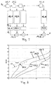
- Figures 4a to 4d show simulation results for a packet-oriented data transmission by means of BPSK via the electrical supply lines.
- the data rate was up 15 ms / s set.
- an equalizer and a Convolutional code used to combat channel interference.
- the graphic representations show the packet error rate in the presence of pulse-like (bursty) noise. Compared the performance with and without the quality estimation according to the invention.
- the SNR is 25 dB and the interference pulses have a length of 1 ⁇ s.
- the advantage The invention is distinctive: interference pulses with levels of over 35dB compared to the background noise can be tolerated. If the quality estimate according to the invention is dispensed with a difference of only 20 dB can be accepted.
- the performance of known ones is achieved by the invention
- Signal transmission method in the presence of pulse-like interference the transmission channel can be improved.
- the invention is suitable for any linear modulation method with FEC, in which the coded symbols with a discrete, preferably small number of constellation points coincide.
Abstract
Description
Die Erfindung betrifft ein Verfahren zum Übertragen von digitalen Daten über einen mit gebündelt auftretenden Störungen behafteten Übertragungskanal, wobei in einem Empfänger nach einer Demodulation eine soft-decision Decodierung unter Berücksichtigung einer geschätzten Signalqualität durchgeführt wird. Ferner bezieht sich die Erfindung auf einen Empfängerschaltkreis zur Durchführung des Verfahrens. The invention relates to a method for transmitting digital data via a bundled interference occurring transmission channel, being in a receiver after demodulation, a soft-decision decoding taking into account an estimated signal quality is performed. The invention further relates to a receiver circuit for performing the method.
Die Liberalisierung der Telekommunikation führt dazu, dass nach Möglichkeiten gesucht wird, breitbandige Übertragungen über bestehende Leitungen und Medien zu realisieren, welche nicht primär für die Datenübertragung ausgelegt sind. Besonders interessant ist die Nutzung des Stromleitungsnetzwerkes, weil an diesem Netzwerk sozusagen alle Haushalte bereits angeschlossen sind. Mit anderen Worten: Das Übertragungsmedium ist vorhanden und muss nur noch in geeigneter Weise genutzt werden.The liberalization of telecommunications means that opportunities are being sought will realize broadband transmissions over existing lines and media, which are not primarily designed for data transmission. It is particularly interesting Use of the power line network, because all households on this network, so to speak are already connected. In other words: the transmission medium is available and only needs to be used appropriately.
Das Problem der elektrischen Stromleitungen (engl. Power Line) besteht darin, dass starke impulsartige Störungen (welche typischerweise von Schaltvorgängen herrühren) vorhanden sind. Auch die sonstigen Störungen (Echos, Einkopplungen etc.) erschweren die Übertragung von breitbandigen Signalen. Stark varierende Störungen können auch bei Funkkanälen auftreten.The problem with electrical power lines is that strong impulsive disturbances (which typically result from switching operations) available. The other disturbances (echoes, coupling etc.) complicate the Broadband signal transmission. Strongly varying faults can also occur Radio channels occur.
Aufgabe der Erfindung ist es, ein Verfahren der eingangs genannten Art anzugeben, das eine verbesserte Detektion in Anwesenheit von impulsartigen bzw. gebündelten (engl. bursty) Störungen liefert.The object of the invention is to provide a method of the type mentioned, which an improved detection in the presence of pulse-like or bundled bursty) provides interference.
Die Lösung der Aufgabe ist durch die Merkmale des Anspruchs 1 definiert. Gemäss der
Erfindung wird die Schätzung der Empfangsqualität mit einer Schaltung durchgeführt, deren
Charakteristik einen Buckel (bzw. S-Linien-Charakteristik) aufweist, welcher bei einem
niedrigeren Verhältnis von Signal zu Rauschen eine Überbewertung bezogen auf eine
lineare Charakteristik und bei einem höheren Verhältnis von Signal zu Rauschen eine
relative Unterbewertung der Signalqualität erzeugt.The solution to the problem is defined by the features of
Bei impulsartigen Störungen wird auf diese Weise der Tatsache Rechnung getragen, dass der Störgeräuschpegel kurzzeitig stark ansteigen kann und dass dann die Zuverlässigkeit der Symbolschätzungen relativ gering ist. Im Prinzip werden die kurzen, stark fehlerbehafteten Signalabschnitte für die Decodierung selektiv als "schlecht" markiert.In the case of impulsive disturbances, the fact that the noise level can rise sharply for a short time and then the reliability the symbol estimates are relatively low. In principle, the short, highly buggy Signal sections for the decoding selectively marked as "bad".
Die Signalqualität bzw. das Verhältnis Signal zu Rauschen wird auf der Basis der Varianz des Störprozesses innerhalb eines vorgegebenen Fensters geschätzt. Gemäss einer bevorzugten Ausführungsform hat dieses Fenster eine Länge im Bereich der kürzesten zu erwartenden Störimpulse. Dadurch wird erreicht, dass die Schätzung der Signalqualität hinreichend schnell auf auftretende Störimpulsbündel reagiert.The signal quality or the signal to noise ratio is based on the variance of the fault process is estimated within a given window. According to a preferred one Embodiment, this window has a length in the range of the shortest to be expected Glitches. This ensures that the estimation of the signal quality is sufficient reacts quickly to occurring interference pulse bundles.
Messungen zeigen, dass bei Stromversorgungsleitungen die auftretenden Störimpulse eine
Länge im Bereich von einigen hundert Nanosekunden bis zu wenigen zehn Mikrosekunden
heben. In dieser Störumgebung heben sich Fensterlängen von typischerweise weniger als
3 µs (z.B von 1 µs) als vorteilhaft erwiesen. Bei einer Symbolrate von z.B. 15 Ms/ s ist eine
Fensterlänge von mindestens etwa N =15 optimal. Eine allzu geringe Länge verschlechtert
die Zuverlässigkeit der Schätzung der Signalqualität. Umgekehrt wird bei einer Länge von
beispielsweise N = 50 die Reaktion auf kurze Störimpulse ungenügend. Die Fensterlänge
sollte deshalb im Bereich von N = 5 bis N = 25, insbesondere im Bereich von N = 5 bis N =
15 liegen.Measurements show that the interference pulses that occur in power supply lines
Length in the range of a few hundred nanoseconds to a few tens of microseconds
to lift. Window lengths of typically less than rise in this
Gemäss einer besonders bevorzugten Ausführungsform wird zur Bestimmung der Signalqualität für eine (entsprechend der Fensterlänge) vorgegebene Anzahl von empfangenden Symbolen geprüft, ob sie innerhalb eines vordefinierten Abstandes zu einem der vorhandenen Konstellationspunkten liegen. Die Anzahl der innerhalb des genannten Abstandes liegenden Symbole wird als Qualitätswert für die nachfolgende soft-decision Decodierung verwendet.According to a particularly preferred embodiment, the signal quality is determined for a predetermined number of receivers (according to the window length) Symbols checked whether they are within a predefined distance from one of the existing ones Constellation points. The number of within the specified distance lying symbols is used as a quality value for the subsequent soft-decision decoding used.
Die Wahl des als Schwellenwert verwendeten Abstandes hängt vorn Modulationsverfahren, von der Statistik der Störimpulse und im Einzelfall von weiteren Parametern ab. In einer ersten Näherung kann der Abstand so gewählt werden, dass bei einem Verhältnis von Signal zu Rauschen von mindestens etwa 5 dB statistisch gesehen die Mehrzahl der Symbole des jeweiligen Fensters innerhalb des vorgegebenen Abstandes zu einem Konstellationspunkt liegen. Versuche haben nämlich gezeigt, dass der Buckel der Charakteristik unterhalb etwa 5 dB liegen sollte. Infolgedessen werden Symbolschätzungen, welche bei etwa 0 dB oder weniger erfolgen, als "schlecht" qualifiziert. Umgekehrt kann bei einem Rauschabstand von mehr als 10 dB von einer zuverlässigen Symbolschätzung ausgegangen werden.The choice of the distance used as a threshold depends on the modulation method, on the statistics of the interference pulses and in individual cases on further parameters. In a First approximation, the distance can be chosen so that with a ratio of Signal to noise of at least about 5 dB statistically, the majority of the symbols of the respective window within the specified distance to a constellation point lie. Experiments have shown that the hump of the characteristic below should be around 5 dB. As a result, symbol estimates, which at about 0 dB or less, qualified as "bad". Conversely, with one Noise ratio of more than 10 dB assumes a reliable symbol estimate become.
Für ein BPSK-Modulationsverfahren (BPSK= Binary Phase Shift Keying) ist ein Abstand von D = 0.5 besonders vorteilhaft. Insgesamt betrachtet lässt sich mit diesem Wert die beste System-Performance erreichen. Selbstverständlich sind andere Werte nicht grundsätzlich ungeeignet.For a BPSK modulation method (BPSK = Binary Phase Shift Keying) a distance of D = 0.5 particularly advantageous. Overall, this value can be the best Achieve system performance. Of course, other values are not fundamental not suitable.
Die Implementation des erfindungsgemässen Verfahrens wirkt sich nur auf den Empfänger aus. Die Senderschaltungen können in an sich bekannter Weise ausgeführt sein.The implementation of the method according to the invention only affects the recipient out. The transmitter circuits can be implemented in a manner known per se.
Im Empfänger wird zwischen der Demodulationsstufe und der soft-decision Decodierung ein Modul eingeschoben, welches gemäss dem beschriebenen Verfahren die Symbolqualität schätzt. Der geschätzte Qualitätswert wird zusammen mit dem Symbolschätzwert in der nachfolgenden Decodierung zur Ermittlung des übertragenen Symbols verwendet. Ob das erfindungsgemässe Modul softwaremässig oder hardwaremässig implementiert wird, ist unwesentlich für die Erfindung.In the receiver there is between the demodulation stage and the soft decision decoding inserted a module, which according to the described method the symbol quality estimates. The estimated quality value is in together with the symbol estimate the subsequent decoding used to determine the symbol transmitted. If the module according to the invention is implemented in software or hardware, is not essential to the invention.
Aus der nachfolgenden Detailbeschreibung und der Gesamtheit der Patentansprüche ergeben sich weitere vorteilhafte Ausführungsformen und Merkmalskombinationen der Erfindung.From the following detailed description and the entirety of the claims there are further advantageous embodiments and combinations of features of the invention.
Die zur Erläuterung des Ausführungsbeispiels verwendeten Zeichnungen zeigen:
- Fig. 1
- Ein Blockschältbild zur Erläuterung der Erfindung;
- Fig. 2
- eine schematische Darstellung einer bevorzugten Ausführungsform der Erfindung;
- Fig. 3
- Beispiele von Kennlinien für verschiedene Abstände D;
- Fig. 4a bis d
- Darstellungen der Performance bei unterschiedlichen Typen von Störgeräuschimpulsen;
- Fig. 1
- A block diagram to explain the invention;
- Fig. 2
- a schematic representation of a preferred embodiment of the invention;
- Fig. 3
- Examples of characteristic curves for different distances D;
- 4a to d
- Representations of the performance with different types of noise impulses;
Grundsätzlich sind in den Figuren gleiche Teile mit gleichen Bezugszeichen versehen.In principle, the same parts are provided with the same reference symbols in the figures.
Fig. 1 zeigt ein Übertragungsschema mit FEC Codierung (FEC=Forward Error Correction)
zwischen einem Sender 1 und einem Empfänger 3. Die digitalen Daten einer Datenquelle 4
werden in einem Coder 5 nach einem an sich bekannten Verfahren zu Symbolen codiert,
zur Ermöglichung einer empfängerseitigen Korrektur von Übertragungsfehlern. Der
Modulator 6 führt eine dem Übertragungskanal 2 angemessene Modulation aus.1 shows a transmission scheme with FEC coding (FEC = Forward Error Correction)
between a
Der Übertragungskanal 2 wird z.B. durch eine Funkübertragungsstrecke oder durch Leitungen
eines elektrischen Stromverteilungsnetzes gebildet. Es wird davon ausgegangen,
dass er mit zeitvarianten Störungen (Störimpulsen, Interferenzen, Echos etc.) behaftet ist.
Für die weiter unten folgenden Beispiele wird angenommen, dass die kürzesten zu erwartenden
Störimpulse eine Länge im Bereich von 1 µs (oder etwas weniger) haben. Bei Abwesenheit
von Störimpulsen wird von einem Störgeräuschabstand von mindestens etwa
10 dB ausgegangen.The
Im Empfänger 3 wird das Empfangssignal im Demodulator 7 (welcher auch einenEqualizer
umfassen kann) demoduliert und im Decoder 9 zur Ermittlung der an die Datensenke 10
abzugebenden Daten decodiert. Beim Decoder 9 handelt es sich um einen nach bekannten
Prinzipien arbeitenden soft-decision Decoder. Erfindungswesentlich ist der Signalqualitätsschätzer
8, welcher die Zuverlässigkeit der vom Demodulator 7 geschätzten Symbole ermittelt
und einen entsprechenden Zuverlässigkeitswert für die soft-decision Decodierung
zur Verfügung stellt.In the
Fig. 2 zeigt ein Blockschaltbild des Signalqualitätsschätzers 8. Dabei wird vorausgesetzt, dass im Sender 1 Symbole einer fest vorgegebenen Konstellation erzeugt werden. Diese Symbole werden in der Regel nacheinander übertragen, können aber auch gleichzeitig (z.B. mit verschiedenen Frequenzen) übertragen werden. Im Rahmen der nachfolgenden Ausführungen wird von einer zeitlichen Reihenfolge ausgegangen.2 shows a block diagram of the signal quality estimator 8. It is assumed that that 1 symbols of a predefined constellation are generated in the transmitter. This Symbols are usually transmitted one after the other, but can also be transmitted simultaneously (e.g. with different frequencies) are transmitted. As part of the following explanations a chronological order is assumed.
Der Störgeräuschprozess (welcher auch auf Interferenzen beruhen kann) kann im Empfänger als zufällig betrachtet werden. Die Störungen werden als gebündelt bzw.impulsartig angenommen (engl. bursty). Damit ist gemeint, dass es eine "gewöhnliche" Störgeräuschleistung (engl. noise power) gibt und dass diese Störgeräuschleistung von Zeit zu Zeit für eine kurze Periode auf einen sehr hohen Wert ansteigt, um nachher auf den "gewöhnlichen" Wert zurückzufallen. Sowohl die Zunahme als auch die Dauer der Erhöhung der Störgeräuschleistung sind zufällig.The noise process (which can also be based on interference) can occur in the receiver can be considered as random. The disturbances are bundled or impulse-like accepted (English bursty). By that is meant that it is an "ordinary" noise performance (Engl. noise power) there and that this noise power from time to time Time for a short period increases to a very high value, afterwards to the "ordinary" Value falling behind. Both the increase and the duration of the increase the noise performance are random.
Gemäss der Erfindung wird für jedes übertragene Symbol die Störgeräuschleistung ermittelt. Ohne Einschränkung der Allgemeinheit kann angenommen werden, dass die Signalleistung bekannt ist (z.B. aufgrund einer Messung zu Beginn des Empfangs eines Datenblockes). Gesucht ist allerdings nicht die momentane Leistung der Störungen, sondern die Varianz des Störgeräuschprozesses zu einer gegebenen Zeit.According to the invention, the noise power is determined for each symbol transmitted. Without restricting generality, it can be assumed that the signal power is known (e.g. due to a measurement at the beginning of the reception of a data block). What is wanted, however, is not the current performance of the faults, but the Variance of the noise process at a given time.
Die Schätzung der Störgeräuschleistung beruht auf einem Block bzw. einem Fenster von N aufeinanderfolgenden Symbolen. Die Länge N des Fensters wird entsprechend dem erwarteten Störgeräuschprozess gewählt. Grössere Fensterlängen führen bei konstanter Signalqualität zu grösserer Genauigkeit, aber zu einer langsameren Reaktion auf Änderungen in der Signalqualität. Bei PLC Anwendungen(PLC = Powerline Communication) mit einer Symbolrate (Symbole pro Sekunde) von z.B. 15 Ms/ s hat sich eine Länge vom N = 15 als vorteilhaft erwiesen. Die kürzesten zu erwartenden Störimpulse liegen nämlich im Bereich von 1 µs. Würde beispielsweise eine Symbolrate von 5 Ms/ s gewählt, wäre eine Länge von N = 5 bis N = 7 vorteilhaft. The noise power estimate is based on a block or window of N successive symbols. The length N of the window becomes the expected one Noise process selected. Larger window lengths result in constant signal quality for greater accuracy, but for a slower response to changes in the signal quality. For PLC applications (PLC = Powerline Communication) with one Symbol rate (symbols per second) of e.g. 15 ms / s has a length of N = 15 as proven advantageous. The shortest expected interference pulses are in the range of 1 µs. For example, if a symbol rate of 5 ms / s were chosen, the length would be N = 5 to N = 7 advantageous.
Der mit dem Fenster ermittelte Störgeräuschpegel wird für das im Zentrum des Fensters liegende Symbol verwendet. Wenn N ungerade ist, hängt das Ergebnis der Signalqualitätsschätzung von (N-1)/ 2 vorangegangenen und von (N-1)/ 2 nachfolgenden demodulierten Symbolen ab sowie vom Symbol, dessen Qualität es zu schätzen gilt. (Die Länge N kann auch gerade sein; wobei dann aber das Schätzverfahren nicht symmetrisch ist. Für die Performance des erfindungsgemässen Verfahrens hat dies aber keine negativen Auswirkungen.)The noise level determined with the window becomes for that in the center of the window lying icon used. If N is odd, the result of the signal quality estimate depends of (N-1) / 2 previous and of (N-1) / 2 subsequent demodulated Symbols as well as from the symbol, the quality of which must be valued. (The length N can also be straight; but then the estimation method is not symmetrical. For the However, the performance of the method according to the invention has no negative effects.)
Die Erfindung ist primär für Situationen bestimmt, in welchen die Signalleistung im wesentlichen konstant und die Störgeräuschleistung variabel ist. Wenn die Signalleistung ebenfalls zeitvariant ist, aber langsamer als die Störgeräuschleistung variiert, kann die Erfindung ebenfalls eingesetzt werden, wobei aber ein zusätzlicher Rechenaufwand zur Verfolgung der Signalleistung erforderlich ist.The invention is primarily intended for situations in which the signal power is essentially constant and the noise performance is variable. If the signal power is also time-varying, but varies more slowly than the noise output, the Invention can also be used, but with an additional computational effort Tracking signal power is required.
Das in Fig. 2 dargestellte Verfahren zur Bestimmung eines Qualitätswertes kann alsnichtlineares FIR Filter (FIR=Finite Impulse Response) dargestellt werden:The method of determining a quality value shown in Figure 2 can be considered non-linear FIR filters (FIR = Finite Impulse Response) are shown:
Die geschätzten Symbole si werden in ein Schieberegister mit N Verzögerungsgliedern 11.1 bis 11.N eingegeben. Der Ausgang eines jeden Verzögerungsgliedes 11.1 bis 11.N wird an je einen Rechner 12.1 bis 12.N weitergegeben. Die Rechner 12.1 bis 12.N bestimmen den Abstand des jeweiligen Symbols zum nächsten Konstellationspunkt. Im Falle einer BPSK-Modulation mit den beiden Konstellationspunkten +1 und -1 wird beispielsweise zunächst festgestellt, ob der Betragswert grösser oder kleiner als 0 ist. Im erstgenannten Fall wird der Euklidische Abstand Di zum Konstellationspunkt +1 und im zweitgenannten Fall der entsprechende Abstand zum Konstellationspunkt -1 berechnet.The estimated symbols si are put into a shift register with N delay elements 11.1 to 11.N entered. The output of each delay element 11.1 to 11.N is passed on to a computer 12.1 to 12.N. Determine the computers 12.1 to 12.N. the distance of the respective symbol to the next constellation point. In the event of BPSK modulation with the two constellation points +1 and -1, for example first determined whether the amount is greater or less than 0. In the former Fall becomes the Euclidean distance Di to the constellation point +1 and in the second If the corresponding distance to the constellation point -1 is calculated.
Im nächsten Schritt wird für jeden Abstand Di in den Vergleichen 13.1 bis 13.N festgestellt, ob der jeweilige Abstand Di kleiner als ein fest vorgegebener Abstand D ist. Fällt der Vergleich positiv aus, d.h. ist der Abstand kleiner, dann wird an Ausgang des jeweiligen Vergleichers 13.1 bis 13.N ein Wert xi = 1 ausgegeben. In the next step it is determined for each distance Di in comparisons 13.1 to 13.N whether the respective distance Di is smaller than a fixed predetermined distance D. Does the fall Comparison positive, i.e. if the distance is smaller, then at the exit of the respective Comparator 13.1 to 13.N a value xi = 1 is output.
Schliesslich berechnen die Addierer 14.1 bis 14.N-1 die Summe aller Werte xi. Aufgrund der obigen Ausführungen ist klar, dass der resultierende Zuverlässigkeitswert x den Wertebereich [0, 1, ..., N] hat.Finally, adders 14.1 to 14.N-1 calculate the sum of all values xi. Because of From the above, it is clear that the resulting reliability value x is the range of values [0, 1, ..., N].
Der Parameter D wird unter Berücksichtigung des Modulations- und Codierverfahrens und
der zu erwartenden Fehlerrate festgelegt. D sollte proportional zur Amplitude des empfangenen
Signals definiert werden. Für eine realwertige bipolare Modulation mit Einheitsamplitude
(BPSK) und einer Faltungscodierung mit einer Rate 1/2 wird ein Wert D = 0.5
bevorzugt.The parameter D is taken into account the modulation and coding method and
the expected error rate. D should be proportional to the amplitude of the received
Signal can be defined. For a real value bipolar modulation with unit amplitude
(BPSK) and convolutional coding with a
Die Berechnung des Qualitätswertes bringt eine Verzögerung von (N-1)/ 2 mit sich. Aus
diesem Grund ist im direkten Weg zwischen Demodulator 7 und Decoder 8 ein Verzögerungsglied
15 entsprechender Grösse einzusetzen.The calculation of the quality value entails a delay of (N-1) / 2. Out
for this reason there is a delay element in the direct path between
Am Anfang und am Ende des Symbolstroms sind besondere Massnahmen erforderlich. Das erste Symbol beispielsweise hat keine Vorgänger. Werden die fehlenden xi mit Nullen initiiert, dann wird die Qualität der ersten paar Symbole unterbewertet, werden sie dagegen mit dem Wert des ersten Symbols initialisiert, dann wird dieses überbewertet.Special measures are required at the beginning and end of the symbol stream. The For example, the first symbol has no predecessors. The missing xi will be with zeros initiated, then the quality of the first few symbols is undervalued, they become on the other hand, initialized with the value of the first symbol, this is then overrated.
Gemäss einer bevorzugten Ausführungsform wird deshalb das Fenster am Anfang und am Ende des Symbolstroms verkürzt, indem beispielsweise beim ersten Symbol nur dieses und die (N+1)/ 2 nachfolgenden Symbole berücksichtigt werden. Beim zweiten bzw. zweitletzten Symbol wird die Qualität beispielsweise auf (N+3)/ 2 Symbolwerte abgestützt (nämlich auf dem ersten bzw. letzten, dem zweiten bzw. zweitletzten und den nachfolgenden (N+1)/ 2 Symbolen). Es ist dabei zu beachten, dass das Ergebnis des Qualitätsschätzers mit einem Faktor A/ N skaliert werden sollte (A bezeichnet die Anzahl gültiger Symbole im Schieberegister (Verzögerungsglieder 11.1 bis 11.N).According to a preferred embodiment, the window is therefore at the beginning and at Shortened the end of the symbol stream, for example by only this for the first symbol and the (N + 1) / 2 subsequent symbols are taken into account. In the second or second to last symbol, the quality is based, for example, on (N + 3) / 2 symbol values (namely on the first or last, the second or second last and the following (N + 1) / 2 symbols). It should be noted that the result of the quality estimator should be scaled with a factor A / N (A denotes the number of valid Symbols in the shift register (delay elements 11.1 to 11.N).
Eine andere Möglichkeit besteht darin, alle Ausgangswerte des Qualitätsschätzers 8 zu ignorieren, welche nicht auf N gültigen Symbolen beruhen. Für die ersten bzw. letzten (N+1)/ 2 Symbole gibt es in diesem Fall keine Schätzwerte der Varianz des Störprozesses. Another possibility consists in closing all the initial values of the quality estimator 8 ignore which are not based on N valid symbols. For the first or last (N + 1) / 2 symbols in this case there are no estimates of the variance of the disturbance process.
Diese Lücken könnten z.B. durch die Wiederholung des ersten bzw. letzten gültigen Schätzwertes gefüllt werden.These gaps could e.g. by repeating the first or last valid Estimated value.
Das allgemeine Blockschaltbild gemäss Fig. 2 kann je nach Umständen vereinfacht werden (z.B. wenn die demodulierten Symbole realwertig und bipolar sind). An dieser Stelle soll aber auf diese Vereinfachungen nicht näher eingegangen werden (weil sie keinen wesentlichen Einfluss auf das Ergebnis haben).The general block diagram according to FIG. 2 can be simplified depending on the circumstances (e.g. if the demodulated symbols are real and bipolar). At this point but these simplifications will not be discussed in more detail (because they are not essential Influence the result).
In Fig. 3 sind beispielhaft drei verschiedene erfindungsgemässe Kennlinien (16.1 bis 16.3) dergestellt. Es sei drauf hingewiesen, dass alle drei Kennlinien monoton sind. Auf der Abszisse ist der Ausgabewert des Signalqualitätsschätzers 8 und auf der Ordinate das Verhältnis von Signal zu Rauschen (SNR) aufgetragen. Ausgegangen wird von einer Fensterlänge von N = 15 und von einem BPSK-Verfahren. Die Kennlinien 16.1 bis 16.3 entsprechen verschiedenen vordefinierten Abständen: D = 0.25, D = 0.50, D = 0.75. Jede Kennlinie verfügt über einen erfindungsgemässen Buckel 17.1 bis 17.3, welcher jeweils im Bereich zwischen -5 bis +5 dB SNR liegt. (Der Buckel bzw. die S-Charakteristik führt dazu, dass die Empfindlichkeit des Ausgangssignals in einem gewissen Bereich weniger sensibel auf Änderungen der SNR reagiert, was dazu beiträgt, dass Ungenauigkeiten bei der Messung der Varianz des Störprozesses, d.h. relativ kurze Fensterlängen, nicht kritisch sind.)3 shows three different characteristic curves according to the invention (16.1 to 16.3) by way of example. created. It should be noted that all three characteristics are monotonic. On the The abscissa is the output value of the signal quality estimator 8 and the ratio on the ordinate plotted from signal to noise (SNR). The starting point is a window length of N = 15 and a BPSK method. The characteristic curves correspond to 16.1 to 16.3 different predefined distances: D = 0.25, D = 0.50, D = 0.75. Every characteristic has a hump 17.1 to 17.3 according to the invention, each in the area is between -5 to +5 dB SNR. (The hump or the S characteristic leads to that the sensitivity of the output signal is less sensitive in a certain range reacts to changes in the SNR, which contributes to inaccuracies in the Measurement of the variance of the disturbance process, i.e. relatively short window lengths, not critical are.)
Die S-Linien-Charakteristik hat bei einem (bezüglich des Arbeitspunktes) niedrigeren
Verhältnis von Signal zu Rauschen eine Überbewertung bezogen auf eine lineare
Vergleichslinie (vgl. z.B. gestrichelte Linie 18 zur Kennlinie 16.1) und bei einem höheren
Verhältnis von Signal zu Rauschen eine relative Unterbewertung der Signalqualität zur
Folge.The S-line characteristic has a lower one (in terms of the working point)
Ratio of signal to noise an overestimation based on a linear
Comparison line (see e.g. dashed
Es ist darauf hinzuweisen, dass das erfindungsgemässe Verfahren für Signal/ Rausch-Verhältnisse im Bereich von ca. 5 dB bis 15 dB besonders geeignet ist. Die Kennlinien sollen durch geeignete Wahl des Abstandparameters D so plaziert sein, dass der Buckel im Bereich des kritischen SNR-Wertes liegt (Modulations- und Codierverfahren haben üblicherweise einen kleinen kritischen Bereich der SNR: Oberhalb dieses Bereiches ist die Performance gut, unterhalb dagegen schlecht). Steigt der Störgeräuschpegel kurzfristig stark an, verschiebt sich der "Arbeitspunkt" vorübergehend an die untere Seite bzw. Ranke des Buckels. Unter den Randbedingungen, welche der Fig. 3 zugrunde liegen, ist die Kennlinie 16.2 die am besten geeignete.It should be noted that the method according to the invention for signal / noise ratios in the range of approx. 5 dB to 15 dB is particularly suitable. The characteristics should be placed by a suitable choice of the distance parameter D so that the hump in the The range of the critical SNR value lies (have modulation and coding methods Usually a small critical area of the SNR: Above this area is the Performance good, below bad. If the noise level increases briefly strongly, the "working point" temporarily shifts to the lower side or Vine of the hump. Under the boundary conditions on which FIG. 3 is based, the Characteristic 16.2 is the most suitable.
Die Figuren 4a bis 4d zeigen Simulationsergebnisse für eine paketorientierte Datenübertragung mittels BPSK über die elektrischen Versorgungsleitungen. Die Datenrate wurde auf 15 Ms/ s festgelegt. Zur Bekämpfung der Kanalstörungen wurden ein Equalizer und ein Faltungscode (engl. convolutional code) eingesetzt. Die grafischen Darstellungen zeigen die Paket-Fehlerrate in Gegenwart von impulsartigen (bursty) Störgeräuschen. Verglichen wird die Performance mit und ohne die erfindungsgemässe Qualitätsschätzung. Die Länge des Filters betrug N = 15 und der vorgegebene Abstand wurde auf D = 0.5 festgelegt.Figures 4a to 4d show simulation results for a packet-oriented data transmission by means of BPSK via the electrical supply lines. The data rate was up 15 ms / s set. To combat channel interference, an equalizer and a Convolutional code used. The graphic representations show the packet error rate in the presence of pulse-like (bursty) noise. Compared the performance with and without the quality estimation according to the invention. The length of the filter was N = 15 and the specified distance was set to D = 0.5.
In allen Simulationen war das Hintergrundrauschen fixiert ("gewöhnliches" Rauschen), und es wurden Störgeräuschimpulse einer vorgegebenen Länge eingeschossen. Auf der Abszisse ist jeweils das Verhältnis des Pegels der Störimpulse zum Pegel des Hintergrundrauschens in dB angegeben. Auf der Ordinate ist die Rate der verlorenen Pakete aufgetragen. Die mit "+" markierten Linien zeigen die Performance ohne die erfindungsgemässe Qualitätsschätzung, die mit "x" markierten Linien zeigen die Performance unter Anwendung der Erfindung.In all simulations the background noise was fixed ("ordinary" noise), and noise pulses of a given length were shot. On the abscissa is the ratio of the level of the interference pulses to the level of the background noise given in dB. The rate of lost packets is plotted on the ordinate. The lines marked with "+" show the performance without the quality estimate according to the invention, the lines marked with "x" show the performance using the Invention.
In Fig. 4a beträgt die SNR 25 dB und die Störimpulse haben eine Länge von 1 µs. Der Vorteil der Erfindung ist markant: Störimpulse mit Pegeln von über 35dB gegenüber dem Hintergrundrauschen können toleriert werden. Bei Verzicht auf die erfindungsgemässe Qualitätsschätzung kann ein Unterschied von nur 20 dB akzeptiert werden.In Fig. 4a, the SNR is 25 dB and the interference pulses have a length of 1 µs. The advantage The invention is distinctive: interference pulses with levels of over 35dB compared to the background noise can be tolerated. If the quality estimate according to the invention is dispensed with a difference of only 20 dB can be accepted.
Fig. 4b basiert ebenfalls auf einer SNR von 25 dB. Allerdings heben die Störimpulse eine Länge von 10 µs. Die Performance ist mit und ohne Qualitätsschätzung erwartungsgemäss schlechter (insgesamt sind gegenüber Fig. 4a mehr Störungen vorhanden). Trotzdem werden durch die Erfindung 10 dB Gewinn erreicht. 4b is also based on an SNR of 25 dB. However, the glitches raise one Length of 10 µs. The performance is as expected with and without a quality estimate worse (overall there are more disturbances compared to FIG. 4a). Still be 10 dB gain achieved by the invention.
Fig. 4c zeigt eine Situation mit 25 dB SNR und mit Störimpulsen einer Länge von 50 µs. Wiederum ist die gesamte Störgeräuschleistung grösser und die Performance in beiden Fällen schlechter. Die Störimpulse sind so lange, dass die Fehlerkorrektur-Codierung den durch die Störimpulse erzeugten Datenverlust nicht kompensieren kann. In diesem Fall kann durch die Erfindung kein Gewinn erzielt werden.4c shows a situation with 25 dB SNR and with interference pulses with a length of 50 μs. Again, the overall noise performance is greater and the performance in both Cases worse. The glitches are so long that the error correction coding cannot compensate for data loss generated by the interference pulses. In this case no profit can be achieved by the invention.
In Fig. 4d schliesslich wurde eine SNR von 15 dB zugrunde gelegt. Die Störimpulse hatten eine Länge von 1 µs. Wiederum wird mit der erfindungsgemässen Qualitätsschätzung eine bessere Performance erreicht. (Bei sehr kleinen Störimpulsen von 10 dB und weniger wird zwar kein Gewinn erreicht, die gesamte Performance der Datenübertragung ist unter diesen Umständen aber so gut, dass die ersichtliche Differenz keine Rolle spielt.)Finally, in Fig. 4d, an SNR of 15 dB was used. The glitches had a length of 1 µs. In turn, the quality estimate according to the invention is used better performance achieved. (With very small interference pulses of 10 dB and less Although no profit was made, the overall performance of data transmission is among them Under certain circumstances, however, so well that the apparent difference does not matter.)
Zusammenfassend ist festzustellen, da durch die Erfindung die Performance von bekannten Signalübertragungsverfahren bei Anwesenheit von impulsartigen Störungen auf dem Übertragungskanal verbessert werden kann. Im Prinzip eignet sich die Erfindung für jedes lineare Modulationsverfahren mit FEC, bei welchem die codierten Symbole mit einer diskreten, vorzugsweise kleinen Anzahl von Konstellationspunkten zusammenfallen.In summary it can be stated that the performance of known ones is achieved by the invention Signal transmission method in the presence of pulse-like interference the transmission channel can be improved. In principle, the invention is suitable for any linear modulation method with FEC, in which the coded symbols with a discrete, preferably small number of constellation points coincide.
Claims (10)
Priority Applications (13)
| Application Number | Priority Date | Filing Date | Title |
|---|---|---|---|
| EP98810582A EP0967761A1 (en) | 1998-06-24 | 1998-06-24 | Transmission method for digital data via a burst error channel |
| CA002335433A CA2335433A1 (en) | 1998-06-24 | 1999-05-19 | Method for transmitting digital data via a transmission channel subject to perturbations occurring in bursts |
| CN99807839A CN1308808A (en) | 1998-06-24 | 1999-05-19 | Method for transmitting digital data via a transmission channel subject to peturbations occuring in bursts |
| IDW20002682A ID28043A (en) | 1998-06-24 | 1999-05-19 | METHOD TO SEND DIGITAL DATA THROUGH THE DELIVERY CHANNEL THAT EXPERIENCES THE INTERFERENCE THAT HAPPENED IN EXPLOSION |
| BR9911466-6A BR9911466A (en) | 1998-06-24 | 1999-05-19 | Procedure for the transmission of digital data through a transmission channel subject to a disturbance beam |
| AU36972/99A AU3697299A (en) | 1998-06-24 | 1999-05-19 | Method for transmitting digital data via a transmission channel subject to perturbations occurring in bursts |
| EP99919020A EP1090489A1 (en) | 1998-06-24 | 1999-05-19 | Method for transmitting digital data via a transmission channel subject to perturbations occurring in bursts |
| KR1020007014405A KR20010071514A (en) | 1998-06-24 | 1999-05-19 | Method for transmitting digital data via a transmission channel which is subject to interference occurring in bursts |
| JP2000556484A JP2003512744A (en) | 1998-06-24 | 1999-05-19 | Method of transmitting digital data over a transmission channel with bursty disturbances |
| PCT/CH1999/000214 WO1999067929A1 (en) | 1998-06-24 | 1999-05-19 | Method for transmitting digital data via a transmission channel subject to perturbations occurring in bursts |
| IL14041099A IL140410A0 (en) | 1998-06-24 | 1999-05-19 | Method for transmitting digital data via a transmission channel subject to perturbations occurring in bursts |
| NO20006502A NO20006502L (en) | 1998-06-24 | 2000-12-20 | Procedure for transmitting digital data via a transmission channel that is bundled with interfering behaviors |
| HK02100801.7A HK1039421A1 (en) | 1998-06-24 | 2002-02-01 | Method for transmitting digital data via a transmission channel subject to perturbations occurring in bursts |
Applications Claiming Priority (1)
| Application Number | Priority Date | Filing Date | Title |
|---|---|---|---|
| EP98810582A EP0967761A1 (en) | 1998-06-24 | 1998-06-24 | Transmission method for digital data via a burst error channel |
Publications (1)
| Publication Number | Publication Date |
|---|---|
| EP0967761A1 true EP0967761A1 (en) | 1999-12-29 |
Family
ID=8236155
Family Applications (2)
| Application Number | Title | Priority Date | Filing Date |
|---|---|---|---|
| EP98810582A Withdrawn EP0967761A1 (en) | 1998-06-24 | 1998-06-24 | Transmission method for digital data via a burst error channel |
| EP99919020A Withdrawn EP1090489A1 (en) | 1998-06-24 | 1999-05-19 | Method for transmitting digital data via a transmission channel subject to perturbations occurring in bursts |
Family Applications After (1)
| Application Number | Title | Priority Date | Filing Date |
|---|---|---|---|
| EP99919020A Withdrawn EP1090489A1 (en) | 1998-06-24 | 1999-05-19 | Method for transmitting digital data via a transmission channel subject to perturbations occurring in bursts |
Country Status (12)
| Country | Link |
|---|---|
| EP (2) | EP0967761A1 (en) |
| JP (1) | JP2003512744A (en) |
| KR (1) | KR20010071514A (en) |
| CN (1) | CN1308808A (en) |
| AU (1) | AU3697299A (en) |
| BR (1) | BR9911466A (en) |
| CA (1) | CA2335433A1 (en) |
| HK (1) | HK1039421A1 (en) |
| ID (1) | ID28043A (en) |
| IL (1) | IL140410A0 (en) |
| NO (1) | NO20006502L (en) |
| WO (1) | WO1999067929A1 (en) |
Families Citing this family (4)
| Publication number | Priority date | Publication date | Assignee | Title |
|---|---|---|---|---|
| AU2003903826A0 (en) * | 2003-07-24 | 2003-08-07 | University Of South Australia | An ofdm receiver structure |
| EP1748573B1 (en) * | 2005-07-29 | 2010-03-31 | Grundfos Management A/S | Method for data transmission between a pump and a controlling unit and corresponding pump. |
| US9413423B1 (en) * | 2015-08-18 | 2016-08-09 | Texas Instruments Incorporated | SNR calculation in impulsive noise and erasure channels |
| KR101626470B1 (en) | 2015-09-16 | 2016-06-01 | (주)계림건축사사무소 | Non-foam type materials for reducing noise and floor system comprising the same |
Citations (3)
| Publication number | Priority date | Publication date | Assignee | Title |
|---|---|---|---|---|
| US4322848A (en) * | 1980-06-26 | 1982-03-30 | Communications Satellite Corporation | Reliability-weighted analog threshold decoder |
| EP0507444A2 (en) * | 1991-03-07 | 1992-10-07 | Matsushita Electric Industrial Co., Ltd. | Data transmission apparatus with error computer and maximal likelihood calculator |
| EP0689312A2 (en) * | 1994-06-21 | 1995-12-27 | NEC Corporation | Soft decision signal outputting receiver |
-
1998
- 1998-06-24 EP EP98810582A patent/EP0967761A1/en not_active Withdrawn
-
1999
- 1999-05-19 AU AU36972/99A patent/AU3697299A/en not_active Abandoned
- 1999-05-19 CN CN99807839A patent/CN1308808A/en active Pending
- 1999-05-19 EP EP99919020A patent/EP1090489A1/en not_active Withdrawn
- 1999-05-19 BR BR9911466-6A patent/BR9911466A/en not_active IP Right Cessation
- 1999-05-19 JP JP2000556484A patent/JP2003512744A/en active Pending
- 1999-05-19 CA CA002335433A patent/CA2335433A1/en not_active Abandoned
- 1999-05-19 IL IL14041099A patent/IL140410A0/en unknown
- 1999-05-19 KR KR1020007014405A patent/KR20010071514A/en not_active Application Discontinuation
- 1999-05-19 WO PCT/CH1999/000214 patent/WO1999067929A1/en not_active Application Discontinuation
- 1999-05-19 ID IDW20002682A patent/ID28043A/en unknown
-
2000
- 2000-12-20 NO NO20006502A patent/NO20006502L/en not_active Application Discontinuation
-
2002
- 2002-02-01 HK HK02100801.7A patent/HK1039421A1/en unknown
Patent Citations (3)
| Publication number | Priority date | Publication date | Assignee | Title |
|---|---|---|---|---|
| US4322848A (en) * | 1980-06-26 | 1982-03-30 | Communications Satellite Corporation | Reliability-weighted analog threshold decoder |
| EP0507444A2 (en) * | 1991-03-07 | 1992-10-07 | Matsushita Electric Industrial Co., Ltd. | Data transmission apparatus with error computer and maximal likelihood calculator |
| EP0689312A2 (en) * | 1994-06-21 | 1995-12-27 | NEC Corporation | Soft decision signal outputting receiver |
Also Published As
| Publication number | Publication date |
|---|---|
| AU3697299A (en) | 2000-01-10 |
| KR20010071514A (en) | 2001-07-28 |
| IL140410A0 (en) | 2002-02-10 |
| CN1308808A (en) | 2001-08-15 |
| WO1999067929A1 (en) | 1999-12-29 |
| HK1039421A1 (en) | 2002-04-19 |
| BR9911466A (en) | 2001-03-20 |
| ID28043A (en) | 2001-05-03 |
| JP2003512744A (en) | 2003-04-02 |
| EP1090489A1 (en) | 2001-04-11 |
| CA2335433A1 (en) | 1999-12-29 |
| NO20006502D0 (en) | 2000-12-20 |
| NO20006502L (en) | 2001-02-23 |
Similar Documents
| Publication | Publication Date | Title |
|---|---|---|
| EP1130867A2 (en) | Receiver and method of detection, for the decoding of a received DQPSK, channel-coded signal | |
| EP0874472A2 (en) | Method and device for informationtransmission on power supply lines | |
| EP1320968B1 (en) | Automatic frequency correction for mobile radio receivers | |
| DE69732153T2 (en) | Method and device for decoding block codes | |
| EP0504546B1 (en) | Method of establishing initial phase synchronisation and adaption of the receive filter of a digital receiver in a baseband transmission system | |
| EP0534399B1 (en) | Time multiplex method for determining the average phase change of a received signal | |
| DE1931992A1 (en) | Procedure for pulse correction | |
| EP0967761A1 (en) | Transmission method for digital data via a burst error channel | |
| EP1210787B1 (en) | Method for estimating the bit error rate in a radio receiver and corresponding radio receiver | |
| CN1288854C (en) | A denoising method for wireless communication system and apparatus applicable to the same method | |
| EP0545159B1 (en) | Digital radio transmission method with channel impulse response estimation | |
| EP0664625A2 (en) | Method for channel quality estimation | |
| DE4311604C1 (en) | Reliability-controlled data detection in receivers for TDMA mobile radio systems | |
| EP1316182B1 (en) | Improved channel equalisation for mobile radio receivers | |
| EP1252716B1 (en) | Method and configuration for decoding information | |
| DE60206538T2 (en) | Receiver for a mobile radio communication terminal | |
| EP1116356B1 (en) | Device and method for regulating the sampling rate in a data transfer system | |
| DE4311655C1 (en) | Channel response adaption procedure in mobile communications receiver - using recursive adaption algorithm to correct initial estimated channel response coeffts. | |
| DE69732634T2 (en) | METHOD FOR DETERMINING THE QUALITY OF A COMPOUND AND RECEIVER | |
| DE2944245C2 (en) | Procedure and arrangement for avoiding the evaluation of pseudo data telegrams | |
| DE3730399A1 (en) | Method and device for transmitting a digital signal | |
| DE4427831C2 (en) | Method and arrangement for the detection of data symbols | |
| DE19735752A1 (en) | Noise suppression method in bipolar data flow | |
| DE10111206C2 (en) | Blind detection for mobile radio receivers | |
| EP1665702B1 (en) | Method for the reconstruction of zero crossing information of noisy angle-modulated signals following limiter-discriminator signal processing |
Legal Events
| Date | Code | Title | Description |
|---|---|---|---|
| PUAI | Public reference made under article 153(3) epc to a published international application that has entered the european phase |
Free format text: ORIGINAL CODE: 0009012 |
|
| AK | Designated contracting states |
Kind code of ref document: A1 Designated state(s): AT BE CH CY DE DK ES FI FR GB GR IE IT LI LU MC NL PT SE |
|
| AX | Request for extension of the european patent |
Free format text: AL;LT;LV;MK;RO;SI |
|
| AKX | Designation fees paid | ||
| REG | Reference to a national code |
Ref country code: DE Ref legal event code: 8566 |
|
| STAA | Information on the status of an ep patent application or granted ep patent |
Free format text: STATUS: THE APPLICATION IS DEEMED TO BE WITHDRAWN |
|
| 18D | Application deemed to be withdrawn |
Effective date: 19991230 |