EP0967597B1 - Magnetic head carriage and actuator assembly - Google Patents
Magnetic head carriage and actuator assembly Download PDFInfo
- Publication number
- EP0967597B1 EP0967597B1 EP99304709A EP99304709A EP0967597B1 EP 0967597 B1 EP0967597 B1 EP 0967597B1 EP 99304709 A EP99304709 A EP 99304709A EP 99304709 A EP99304709 A EP 99304709A EP 0967597 B1 EP0967597 B1 EP 0967597B1
- Authority
- EP
- European Patent Office
- Prior art keywords
- carriage
- coil
- guide rail
- assembly according
- motor
- Prior art date
- Legal status (The legal status is an assumption and is not a legal conclusion. Google has not performed a legal analysis and makes no representation as to the accuracy of the status listed.)
- Expired - Lifetime
Links
Images


Classifications
-
- G—PHYSICS
- G11—INFORMATION STORAGE
- G11B—INFORMATION STORAGE BASED ON RELATIVE MOVEMENT BETWEEN RECORD CARRIER AND TRANSDUCER
- G11B5/00—Recording by magnetisation or demagnetisation of a record carrier; Reproducing by magnetic means; Record carriers therefor
- G11B5/48—Disposition or mounting of heads or head supports relative to record carriers ; arrangements of heads, e.g. for scanning the record carrier to increase the relative speed
- G11B5/58—Disposition or mounting of heads or head supports relative to record carriers ; arrangements of heads, e.g. for scanning the record carrier to increase the relative speed with provision for moving the head for the purpose of maintaining alignment of the head relative to the record carrier during transducing operation, e.g. to compensate for surface irregularities of the latter or for track following
- G11B5/584—Disposition or mounting of heads or head supports relative to record carriers ; arrangements of heads, e.g. for scanning the record carrier to increase the relative speed with provision for moving the head for the purpose of maintaining alignment of the head relative to the record carrier during transducing operation, e.g. to compensate for surface irregularities of the latter or for track following for track following on tapes
-
- G—PHYSICS
- G11—INFORMATION STORAGE
- G11B—INFORMATION STORAGE BASED ON RELATIVE MOVEMENT BETWEEN RECORD CARRIER AND TRANSDUCER
- G11B5/00—Recording by magnetisation or demagnetisation of a record carrier; Reproducing by magnetic means; Record carriers therefor
- G11B5/48—Disposition or mounting of heads or head supports relative to record carriers ; arrangements of heads, e.g. for scanning the record carrier to increase the relative speed
- G11B5/56—Disposition or mounting of heads or head supports relative to record carriers ; arrangements of heads, e.g. for scanning the record carrier to increase the relative speed with provision for moving the head support for the purpose of adjusting the position of the head relative to the record carrier, e.g. manual adjustment for azimuth correction or track centering
Definitions
- the present invention relates generally to servo positioned actuators, and more particularly, to a carriage and positioning actuator assembly in which at least part of the carriage is positioned within the central portion of the motor.
- Information is recorded on and read from a moving magnetic tape with a magnetic read/write head positioned next to the tape.
- the magnetic "head" may be a single head or, as is common, a series of read/write head elements stacked individually and/or in pairs within the head unit. Data is recorded in tracks on the tape by moving the tape lengthwise past the head.
- the head elements are selectively activated by electric currents representing the information to be recorded on the tape.
- the information is read from the tape by moving the tape longitudinally past the head elements so that magnetic flux patterns on the tape create electric signals in the head elements. These signals represent the information stored on the tape.
- Data is recorded on and read from each of the parallel tracks on the tape by positioning the head elements at different locations across the tape. That is, head elements are moved from track to track as necessary to either record or read the desired information. Movement of the magnetic head is controlled by an actuator operatively coupled to some type of servo control circuitry. Tape drive head positioning actuators often include a lead screw driven by a stepper motor, a voice coil motor, or a combination of both. The carriage that supports the head is driven by the actuator along a path perpendicular to the direction that the tape travels. The head elements are positioned as close to the center of a track as possible based upon the servo information recorded on the tape.
- JP-A-4 060 915 discloses a magnetic recording device that is arranged to detect and control the position of the magnetic head. This prior art is reflected by the preamble of claim 1.
- US 4,525,696 discloses a driver for rotating a magnetic head.
- the present invention is directed in general to a servo positioned carriage and actuator assembly and, more particularly, to a head carriage and actuator assembly for a tape drive.
- a part of the carriage is positioned within the central portion of the motor.
- the motor typically a voice coil motor, includes a coil of electrically conductive windings and a magnet or magnets adjacent to the coil.
- the central portion of the motor is defined by a perimeter of the magnets and the carriage is positioned at least partially inside this perimeter.
- the carriage for example, will typically include a ring shaped center portion in which the coil is mounted. This ring shaped center portion mounting the coil is positioned inside the magnets to help minimize the overall mass of the carriage elements of the assembly.
- a magnetic tape 12 is wound on a single supply spool 14 and tape cartridge 16.
- Tape cartridge 16 is inserted into tape drive 10 for read and write operations.
- Tape 12 passes around tape guide 17, over a magnetic read/write head 18, around tape guide 19 to take up spool 20.
- Head 18 is mounted to a head carriage and actuator assembly 22 that includes a variety of operational features related to head 18. Head carriage and actuator assembly 22 is also referred to for convenience as actuator 22.
- Magnetic head 18 engages tape 12 as tape 12 moves across the face of head 18 to record data on tape 12 and to read data from tape 12.
- Fig. 2 is a perspective view of the actuator 22.
- Figs. 3, 4 and 5 are elevation and plan views of actuator 22.
- the operative components of actuator 22 are best seen in Figs. 3-5.
- head 18 is carried by a moveable carriage 24.
- Carriage 24 moves up and down along a primary guide rail 26 and a secondary guide rail 28 at the urging of voice coil motor 30.
- Head 18, which is carried by carriage 24, therefore, also moves up and down in a direction perpendicular to the direction of tape travel as desired to properly position head 18 for reading and writing operations.
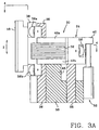
- Figs. 3A and 3B show carriage 24 and head 18 in different positions along the guide rails.
- Voice coil motor 30 includes a coil 32 and magnets 34. Magnets 34 are attached to the inside of sidewalls 54 of actuator base 50. Top flux plate 36 fits on top of sidewalls 54 of base 50. Actuator base 50 is secured to the frame or another stable component of tape drive 10. Coil 32 is mounted to carriage 24.
- carriage 24 includes a front portion 38, a back portion 40 and truncated ring shaped center portions 42A and 42B that join the front and back portions 38, 40.
- Center portions 42A and 42B are positioned inside a circumferential perimeter defined by magnets 34.
- the ring shaped center portions 42A and 42B are spaced apart a distance equal to or slightly greater than the height (the axial dimension) of coil 32.
- Coil 32 is sandwiched between and firmly attached to ring shaped center portions 42B and 42C in carriage 24. Coil 32 is exposed at cavities 44 formed on each side of carriage 24 between ring shaped center portions 42A and 428.
- a post 46 extends vertically through the center portion of coil 32.
- post 46 is the upright core portion of actuator base 50.
- Primary guide rail 26 extends up along a V-shaped trough 48 formed in the front side of core 42.
- Secondary guide rail 28 is positioned at the back of carriage 24 just outside coil 32.
- Head 18 is mounted to front piece 38 of carriage 24.
- a position sensor 52 that reads the vertical position of carriage 24 may be mounted between back piece 40 and actuator base 50.
- Carriage 24 travels along primary guide rail 26 on two pairs of bearings 56A and 56B mounted in the front piece 38 of carriage 24.
- Carriage 24 travels along secondary guide rail 28 on one pair of bearings 58 mounted in the back piece 40 of carriage 24.
- bearings 56A are mounted at the top of carriage 24
- bearings 56B are mounted at the bottom 62 of carriage 24
- bearings 58 are mounted at the middle of carriage 24.
- bearings 56A and 56B control the position of carriage 24 in the azimuth direction, indicated by arrow A in Fig. 5, and the zenith direction, indicated by arrow Z in Fig. 3A.
- Bearings 58 control the position of carriage 24 in the yaw direction, indicated by arrow Y in Fig. 4.
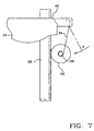
- FIG. 7 One type of bearing preload mechanism is shown in Fig. 7. Referring to Fig. 7, one or both of the secondary rail bearings 58 are spring mounted against secondary guide rail 28. A spring 64 extends between back portion 40 of carriage 24 and bearing shaft 59. Spring 64 generates a spring force F that pushes bearing 58 against secondary guide rail 28 and to pulls carriage 24 rearward. The rearward pull of carriage 24 urges the primary guide rail bearings 56 against primary guide 26.
- actuator 22 positions head 18 relative to tape 12 according to positional information recorded on tape 12. It may be desirable, and in some cases necessary, to make one or all of top flux plate 36, post 46 and actuator base 50 from a soft magnetic steel to carry the magnetic flux 66 generated by magnets 34 through the space occupied by coil 32, as shown in Fig. 8.
- a servo control signal is generated from the positional information on tape 12 through servo control circuitry (not shown) and delivered as an electrical current to voice coil 32.
- the presence of current in coil 32 in the magnetic field generated by magnets 34 creates a vertical force on coil 32 and, correspondingly, on carriage 24. This vertical force moves carriage 24 and head 18 up or down as necessary to properly position head 18 relative to tape 12.
- the position of primary guide rail 26 inside coil 32 and the position of bearings 56A and 56B above and below coil 32 minimizes the amount of mass needed at the back of carriage 24 to place the center of gravity of carriage 24 at the same location as the center of force exerted by voice coil motor 30. Positioning the center of gravity of carriage 24 at the same location as the center of force of voice coil motor 30 reduces the amplitude of the carriage rocking modes. So, by locating primary guide rail 26 inside coil 32, the overall mass of carriage 24 can be reduced. A more compact design can also be achieved by positioning coil 32 between primary guide rail bearings 56A and 56B. This configuration allows the positioning of head 18 closer to the center of force of voice coil motor 30 to further reduce the size and mass of carriage 24.
- fastening primary guide rail 26 to post 46 eliminates the need to provide other support for primary guide rail 26, particularly at the ends of the primary guide rail.
- the added stiffness allows higher resonant frequencies of the rocking modes of carriage 24 and, hence, a higher band width for the servo control system.
- carriage 24, or at least one of the center portions 42A and 42B, are made of conductive material, then the carriage will form an electrically conductive loop in the magnetic flux of voice coil motor 30. The movement of carriage 24 as it is driven by motor 30, therefore, will generate an electrical current through this conductive loop. The current in carriage 24 generates a damping force that acts on carriage 24 in a direction opposite the direction of travel and is proportional to the velocity of the carriage. This damping force can be avoided by making carriage 24, or at least the center portions 42A and 42B, from a non-conductive material or by forming a non-conductive break in the otherwise conductive carriage loop. Fig. 6C shows such a non-conductive break in carriage 24. Referring to Fig.
- a strip 41 of adhesive material fills a break made in carriage 24 near one of the junctions of back portions 40 and center portions 42A and 42B.
- any electrically non-conductive material may be used, an epoxy or other strong adhesive is preferred to help maintain the structural integrity of carriage 24.
- Bearings as used in this Specification and in the Claims means any suitable object, structure or surface that moveably supports the carriage for travel along the rails.
- Suitable bearings may include, for example, ball bearings, roller bearings, Gothic arch bearings, journal bearings, bushings and the like.
- the invention may be embodied in other carriage and actuator assemblies, structures and designs.
- the invention could be incorporated in many different types of servo positioned actuators that use a voice coil motor.
- the voice coil motor might be configured so that the magnets are secured to the carriage and the coil remains stationary. And, the coil need not be annular. A square or rectangular coil may be appropriate in some applications.
- the post and the primary guide rail could be formed as an integral unit, rather the discrete components described above.
- the sidewalls of the actuator base might be formed integral to the base foundation, as shown in Figs. 2, 5 and 6, or the sidewalls might be formed integral with the top plate and separate from the base. Therefore, it is to be understood that these and other variations of and modifications to the embodiments shown and described may be made without departing from the scope of the invention as defined in following claims.
Description
- The present invention relates generally to servo positioned actuators, and more particularly, to a carriage and positioning actuator assembly in which at least part of the carriage is positioned within the central portion of the motor.
- Information is recorded on and read from a moving magnetic tape with a magnetic read/write head positioned next to the tape. The magnetic "head" may be a single head or, as is common, a series of read/write head elements stacked individually and/or in pairs within the head unit. Data is recorded in tracks on the tape by moving the tape lengthwise past the head. The head elements are selectively activated by electric currents representing the information to be recorded on the tape. The information is read from the tape by moving the tape longitudinally past the head elements so that magnetic flux patterns on the tape create electric signals in the head elements. These signals represent the information stored on the tape.
- Data is recorded on and read from each of the parallel tracks on the tape by positioning the head elements at different locations across the tape. That is, head elements are moved from track to track as necessary to either record or read the desired information. Movement of the magnetic head is controlled by an actuator operatively coupled to some type of servo control circuitry. Tape drive head positioning actuators often include a lead screw driven by a stepper motor, a voice coil motor, or a combination of both. The carriage that supports the head is driven by the actuator along a path perpendicular to the direction that the tape travels. The head elements are positioned as close to the center of a track as possible based upon the servo information recorded on the tape.
- JP-A-4 060 915 discloses a magnetic recording device that is arranged to detect and control the position of the magnetic head. This prior art is reflected by the preamble of
claim 1. US 4,525,696 discloses a driver for rotating a magnetic head. - The present invention is directed in general to a servo positioned carriage and actuator assembly and, more particularly, to a head carriage and actuator assembly for a tape drive. A part of the carriage is positioned within the central portion of the motor. The motor, typically a voice coil motor, includes a coil of electrically conductive windings and a magnet or magnets adjacent to the coil. In one embodiment of the invention, the central portion of the motor is defined by a perimeter of the magnets and the carriage is positioned at least partially inside this perimeter. The carriage, for example, will typically include a ring shaped center portion in which the coil is mounted. This ring shaped center portion mounting the coil is positioned inside the magnets to help minimize the overall mass of the carriage elements of the assembly.
- The invention is specified in
claim 1. Embodiments of the invention are specified in the sub-claims. -
- Fig. 1 is a top down plan view of a tape drive incorporating a head positioning actuator constructed according to one embodiment of the invention.
- Fig. 2 is a perspective view of the moveable carriage and head positioning actuator of Fig. 1.
- Figs. 3A and 3B are side elevation and partial section views of the moveable carriage and head positioning actuator of Figs. 1 and 2 in different positions along the guide rails.
- Fig. 4 is a top down plan and partial section view of the moveable carriage and head positioning actuator taken along the line 4-4 in Fig. 3A.
- Fig. 5 is a front elevation and partial cut-away view of the moveable carriage and head positioning actuator as viewed along the line 5-5 in Fig. 4.
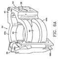
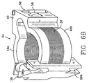
- Figs. 6A, 6B and 6C are detail perspective views of the head carriage. Fig. 6A illustrates the carriage without the coil. Fig. 6B illustrates the carriage with the coil installed in the carriage. Fig. 6C illustrates a carriage in which a non-conductive break is made between the center portions of the carriage and the back portion of the carriage.
- Fig. 7 is a detail side elevation view of the back portion of the carriage showing one type of bearing preload mechanism.
- Fig. 8 is a representational side view of the actuator showing the magnetic flux in the voice coil motor.
-
- Referring first to Fig.1, a
magnetic tape 12 is wound on asingle supply spool 14 andtape cartridge 16.Tape cartridge 16 is inserted intotape drive 10 for read and write operations.Tape 12 passes aroundtape guide 17, over a magnetic read/writehead 18, aroundtape guide 19 to take upspool 20.Head 18 is mounted to a head carriage andactuator assembly 22 that includes a variety of operational features related tohead 18. Head carriage andactuator assembly 22 is also referred to for convenience asactuator 22.Magnetic head 18 engagestape 12 astape 12 moves across the face ofhead 18 to record data ontape 12 and to read data fromtape 12. - Fig. 2 is a perspective view of the
actuator 22. Figs. 3, 4 and 5 are elevation and plan views ofactuator 22. The operative components ofactuator 22 are best seen in Figs. 3-5. Referring to Figs. 2-5,head 18 is carried by amoveable carriage 24. Carriage 24 moves up and down along aprimary guide rail 26 and asecondary guide rail 28 at the urging ofvoice coil motor 30.Head 18, which is carried bycarriage 24, therefore, also moves up and down in a direction perpendicular to the direction of tape travel as desired to properly positionhead 18 for reading and writing operations. Figs. 3A and 3B showcarriage 24 and head 18 in different positions along the guide rails. -
Voice coil motor 30 includes acoil 32 andmagnets 34.Magnets 34 are attached to the inside ofsidewalls 54 ofactuator base 50.Top flux plate 36 fits on top ofsidewalls 54 ofbase 50.Actuator base 50 is secured to the frame or another stable component oftape drive 10.Coil 32 is mounted tocarriage 24. - The details of
carriage 24 are best seen in Figs. 6A and 6B. Fig. 6A is a perspective view ofcarriage 24 withoutcoil 32. Fig. 6B is a perspective view ofcarriage 24 withcoil 32 installed. Referring to Figs. 6A and 6B,carriage 24 includes afront portion 38, aback portion 40 and truncated ring shaped center portions 42A and 42B that join the front andback portions magnets 34. The ring shaped center portions 42A and 42B are spaced apart a distance equal to or slightly greater than the height (the axial dimension) ofcoil 32.Coil 32 is sandwiched between and firmly attached to ring shaped center portions 42B and 42C incarriage 24.Coil 32 is exposed atcavities 44 formed on each side ofcarriage 24 between ring shaped center portions 42A and 428. - Referring again to Figs. 2-5, a
post 46 extends vertically through the center portion ofcoil 32. In the embodiment of the invention shown in the drawings, post 46 is the upright core portion ofactuator base 50.Primary guide rail 26 extends up along a V-shapedtrough 48 formed in the front side ofcore 42.Secondary guide rail 28 is positioned at the back ofcarriage 24 just outsidecoil 32.Head 18 is mounted tofront piece 38 ofcarriage 24. If necessary or desirable, aposition sensor 52 that reads the vertical position ofcarriage 24 may be mounted betweenback piece 40 andactuator base 50.Carriage 24 travels alongprimary guide rail 26 on two pairs of bearings 56A and 56B mounted in thefront piece 38 ofcarriage 24.Carriage 24 travels alongsecondary guide rail 28 on one pair ofbearings 58 mounted in theback piece 40 ofcarriage 24. Preferably, bearings 56A are mounted at the top ofcarriage 24, bearings 56B are mounted at the bottom 62 ofcarriage 24, andbearings 58 are mounted at the middle ofcarriage 24. In this configuration, bearings 56A and 56B control the position ofcarriage 24 in the azimuth direction, indicated by arrow A in Fig. 5, and the zenith direction, indicated by arrow Z in Fig. 3A.Bearings 58 control the position ofcarriage 24 in the yaw direction, indicated by arrow Y in Fig. 4. - It may be desirable to preload one or both
bearings 58 againstsecondary rail 28 to maintain contact of all of the bearings against the rails. One type of bearing preload mechanism is shown in Fig. 7. Referring to Fig. 7, one or both of thesecondary rail bearings 58 are spring mounted againstsecondary guide rail 28. Aspring 64 extends betweenback portion 40 ofcarriage 24 and bearingshaft 59.Spring 64 generates a spring force F that pushes bearing 58 againstsecondary guide rail 28 and to pullscarriage 24 rearward. The rearward pull ofcarriage 24 urges the primary guide rail bearings 56 againstprimary guide 26. - In operation, actuator 22 positions head 18 relative to tape 12 according to positional information recorded on
tape 12. It may be desirable, and in some cases necessary, to make one or all oftop flux plate 36,post 46 andactuator base 50 from a soft magnetic steel to carry themagnetic flux 66 generated bymagnets 34 through the space occupied bycoil 32, as shown in Fig. 8. A servo control signal is generated from the positional information ontape 12 through servo control circuitry (not shown) and delivered as an electrical current tovoice coil 32. The presence of current incoil 32 in the magnetic field generated bymagnets 34 creates a vertical force oncoil 32 and, correspondingly, oncarriage 24. This vertical force movescarriage 24 andhead 18 up or down as necessary to properly positionhead 18 relative to tape 12. - The position of
primary guide rail 26 insidecoil 32 and the position of bearings 56A and 56B above and belowcoil 32 minimizes the amount of mass needed at the back ofcarriage 24 to place the center of gravity ofcarriage 24 at the same location as the center of force exerted byvoice coil motor 30. Positioning the center of gravity ofcarriage 24 at the same location as the center of force ofvoice coil motor 30 reduces the amplitude of the carriage rocking modes. So, by locatingprimary guide rail 26 insidecoil 32, the overall mass ofcarriage 24 can be reduced. A more compact design can also be achieved by positioningcoil 32 between primary guide rail bearings 56A and 56B. This configuration allows the positioning ofhead 18 closer to the center of force ofvoice coil motor 30 to further reduce the size and mass ofcarriage 24. - It is desirable to glue or otherwise fasten
primary guide rail 26 to post 46 to increase the stiffness ofprimary guide rail 26. In addition, fasteningprimary guide rail 26 to post 46 eliminates the need to provide other support forprimary guide rail 26, particularly at the ends of the primary guide rail. The added stiffness allows higher resonant frequencies of the rocking modes ofcarriage 24 and, hence, a higher band width for the servo control system. It is also desirable to separate upper guide bearings 56A from lower guide bearings 56B as much as possible without exceeding the vertical height limitations ofactuator 22 andtape drive 10. Since the lowest stiffness member in determining the carriage rocking frequencies is the bearings, spreading the bearings as far apart as possible increases the effective stiffness of the carriage guide system. So, by maximizing the spacing between bearings 56A and 56B, the resonant frequency of the carriage rocking modes can be made as high as possible for a given stiffness of bearings. - If
carriage 24, or at least one of the center portions 42A and 42B, are made of conductive material, then the carriage will form an electrically conductive loop in the magnetic flux ofvoice coil motor 30. The movement ofcarriage 24 as it is driven bymotor 30, therefore, will generate an electrical current through this conductive loop. The current incarriage 24 generates a damping force that acts oncarriage 24 in a direction opposite the direction of travel and is proportional to the velocity of the carriage. This damping force can be avoided by makingcarriage 24, or at least the center portions 42A and 42B, from a non-conductive material or by forming a non-conductive break in the otherwise conductive carriage loop. Fig. 6C shows such a non-conductive break incarriage 24. Referring to Fig. 6C, astrip 41 of adhesive material fills a break made incarriage 24 near one of the junctions ofback portions 40 and center portions 42A and 42B. Although any electrically non-conductive material may be used, an epoxy or other strong adhesive is preferred to help maintain the structural integrity ofcarriage 24. - "Bearings" as used in this Specification and in the Claims means any suitable object, structure or surface that moveably supports the carriage for travel along the rails. Suitable bearings may include, for example, ball bearings, roller bearings, Gothic arch bearings, journal bearings, bushings and the like.
- Although the invention has been shown and described with reference to a head carriage and actuator assembly for a tape drive, the invention may be embodied in other carriage and actuator assemblies, structures and designs. For example, the invention could be incorporated in many different types of servo positioned actuators that use a voice coil motor. The voice coil motor might be configured so that the magnets are secured to the carriage and the coil remains stationary. And, the coil need not be annular. A square or rectangular coil may be appropriate in some applications. The post and the primary guide rail could be formed as an integral unit, rather the discrete components described above. The sidewalls of the actuator base might be formed integral to the base foundation, as shown in Figs. 2, 5 and 6, or the sidewalls might be formed integral with the top plate and separate from the base. Therefore, it is to be understood that these and other variations of and modifications to the embodiments shown and described may be made without departing from the scope of the invention as defined in following claims.
Claims (12)
- A carriage and actuator assembly, comprising:a motor (30) comprising a coil (32) of electrically conductive windings and a magnet (34) surrounding at least a part of the coil (32);a moveable carriage (24) operatively coupled to the motor (30) and at least part of the carriage (24) disposed within a central portion of the motor (30); and characterized byfirst (26) and second (28) guide rails along which the carriage is moveable in an axial direction of the motor.
- The assembly according to Claim 1, wherein the central portion of the motor (30) is defined by a perimeter of the magnet (34).
- The assembly according to Claim 1, wherein the carriage (24) comprises a first portion (38) for carrying a payload (18) and a second portion (42A or 42B) mounting the coil (32), the second portion (42A or 42B) of the carriage (24) mounting the coil (32) positioned inside the central portion of the motor (30).
- The assembly according to Claim 1, wherein at least part of the carriage (24) disposed within the central portion of the motor (30) forms an electrically conductive loop.
- The assembly according to Claim 2, wherein at least part of the carriage (24) disposed within a perimeter of the magnet (34) forms an electrically conductive loop.
- The assembly according to Claim 1, wherein the first guide rail (26) extends axially through the central portion of the motor (30), the carriage (24) moveable along the first guide rail (26).
- The assembly according to Claim 6, wherein the second guide rail (28) is positioned parallel to the first guide rail (26).
- The assembly according to Claim 7, further comprising first bearings (56A or 56B) mounted to the carriage (24) and second bearings (58) mounted to the carriage (24) at a location spaced apart from the first bearings (56A or 56B), the first bearings (56A or 56B) engaging the first guide rail (26) to facilitate movement of the carriage (24) along the first guide rail (26) and the second bearings (58) engaging the second guide rail (28) to facilitate movement of the carriage (24) along the second guide rail (28).
- The assembly according to Claim 1, wherein the coil is an annular coil (32) of electrically conductive windings.
- The assembly according to Claim 9, wherein the assembly comprises a pair of arcuate magnets (34) surrounding at least part of the coil (32) and defining an arcuate perimeter around the coil (32).
- The assembly according to claim 9, wherein the carriage comprises a first portion (38) configured to carry a payload (18) and a generally ring shaped second portion (42A or 42B) mounting the coil (32), the second portion (42A or 42B) of the carriage (24) disposed within the arcuate perimeter of the magnets (34).
- The assembly according to Claim 11, wherein the second portion (42A or 42B) of the carriage (24) is made of electrically conductive material.
Applications Claiming Priority (2)
| Application Number | Priority Date | Filing Date | Title |
|---|---|---|---|
| US103068 | 1998-06-22 | ||
| US09/103,068 US6411474B1 (en) | 1998-06-22 | 1998-06-22 | Carriage and actuator assembly |
Publications (2)
| Publication Number | Publication Date |
|---|---|
| EP0967597A1 EP0967597A1 (en) | 1999-12-29 |
| EP0967597B1 true EP0967597B1 (en) | 2004-02-11 |
Family
ID=22293201
Family Applications (1)
| Application Number | Title | Priority Date | Filing Date |
|---|---|---|---|
| EP99304709A Expired - Lifetime EP0967597B1 (en) | 1998-06-22 | 1999-06-16 | Magnetic head carriage and actuator assembly |
Country Status (4)
| Country | Link |
|---|---|
| US (1) | US6411474B1 (en) |
| EP (1) | EP0967597B1 (en) |
| JP (1) | JP2000048336A (en) |
| DE (1) | DE69914673T2 (en) |
Families Citing this family (8)
| Publication number | Priority date | Publication date | Assignee | Title |
|---|---|---|---|---|
| US6594118B1 (en) * | 2000-02-03 | 2003-07-15 | Seagate Removable Storage Solutions Llc | Suspension system for a head-carriage assembly for a magnetic tape drive |
| DE60108002T2 (en) * | 2000-06-21 | 2005-12-29 | Fisher & Paykel Healthcare Ltd., East Tamaki | Piping with heated wick |
| US7227724B2 (en) * | 2003-01-30 | 2007-06-05 | Certance, Llc | Head actuator assembly for a tape drive |
| US6985430B1 (en) * | 2003-11-18 | 2006-01-10 | Storage Technology Corporation | Transducer positioning device |
| US7679864B2 (en) * | 2006-06-08 | 2010-03-16 | Quantum Corporation | Narrow width actuator for tape drive systems |
| US7474495B2 (en) * | 2007-02-20 | 2009-01-06 | Quantum Corporation | Piezoelectric micro-actuator for magnetic tape read/write head |
| US8059355B2 (en) * | 2009-06-08 | 2011-11-15 | Quantum Corporation | Dual stage head actuator assembly for tape drive |
| US11735223B2 (en) * | 2021-06-29 | 2023-08-22 | Western Digital Technologies, Inc. | Head suspension system for a tape drive |
Family Cites Families (30)
| Publication number | Priority date | Publication date | Assignee | Title |
|---|---|---|---|---|
| US4314295A (en) | 1979-10-18 | 1982-02-02 | Burroughs Corporation | Linear actuator with staggered flat coils |
| US4525696A (en) | 1980-11-28 | 1985-06-25 | Minnesota Mining & Manufacturing Company | Driver for rotating a magnetic playback head |
| JPS59168924A (en) | 1983-03-17 | 1984-09-22 | Toshiba Corp | Magnetic head moving device |
| US4609958A (en) | 1984-05-29 | 1986-09-02 | Cipher Data Products, Inc. | Precision bearing for reciprocating a magnetic head |
| US4754352A (en) | 1985-05-21 | 1988-06-28 | Alps Electric Co., Ltd. | Magnetic drum recording apparatus |
| US4694367A (en) | 1985-11-15 | 1987-09-15 | Tallgrass Technologies, Inc. | Mechanism for moving recording heads across computer tapes |
| US4870703A (en) | 1986-12-15 | 1989-09-26 | Raymond Engineering Inc. | Magnetic disc memory unit |
| US5012372A (en) * | 1987-10-20 | 1991-04-30 | Kabushiki Kaisha Toshiba | Head access mechanism for moving heads |
| US5041935A (en) * | 1988-08-17 | 1991-08-20 | Fujitsu Limited | Rotary actuator for positioning magnetic heads in a disk drive |
| EP0562646B1 (en) | 1989-06-13 | 1996-08-21 | Kabushiki Kaisha Toshiba | Electro-magnetic actuator and optical disk |
| JPH0746425B2 (en) | 1989-07-06 | 1995-05-17 | 松下電器産業株式会社 | Optical recording / reproducing device |
| JPH03203032A (en) | 1989-12-28 | 1991-09-04 | Toshiba Corp | Optical system moving device |
| US5243591A (en) | 1990-04-23 | 1993-09-07 | Asahi Kogaku Kogyo Kabushiki Kaisha | Protecting a read/write head from damage |
| JPH087854B2 (en) | 1990-06-26 | 1996-01-29 | 三菱電機株式会社 | Magnetic recording / reproducing device |
| US5105322A (en) | 1990-06-29 | 1992-04-14 | Digital Equipment Corporation | Transverse positioner for read/write head |
| JPH04143932A (en) | 1990-10-05 | 1992-05-18 | Olympus Optical Co Ltd | Optical head driver |
| JP2558387B2 (en) * | 1990-11-16 | 1996-11-27 | 株式会社日立製作所 | Voice coil motor and magnetic disk device |
| EP0565918B1 (en) * | 1992-04-13 | 1998-05-20 | Imation Corp. | Head positioning mechanism for multitrack tape recorder |
| JP3094662B2 (en) * | 1992-05-20 | 2000-10-03 | ソニー株式会社 | Recording and playback device |
| CN1044417C (en) | 1992-08-24 | 1999-07-28 | 株式会社三协精机制作所 | Unit for driving of objective |
| US5278820A (en) | 1992-09-28 | 1994-01-11 | Eastman Kodak Company | Apparatus and method for a radial access mechanism for a disk player/recorder |
| US5377052A (en) * | 1993-06-14 | 1994-12-27 | International Business Machines Corporation | Actuator assembly for servo-controlled magnetic tape head |
| KR950001733A (en) | 1993-06-30 | 1995-01-03 | 배순훈 | Pickup transfer device using Hyper Cycloid Gearing |
| JP3279024B2 (en) | 1993-10-30 | 2002-04-30 | ソニー株式会社 | Optical pickup device |
| WO1995016986A2 (en) | 1993-12-15 | 1995-06-22 | Conner Peripherals, Inc. | Voice coil driven positioner for coarse and fine positioning of magnetic head in multi-track tape drive |
| NO944103D0 (en) | 1994-10-27 | 1994-10-27 | Abb Nera As Seksjon Contec | Device by linear actuator |
| US5519554A (en) * | 1994-11-17 | 1996-05-21 | Storage Technology Corporation | Rack and pinion linear slide read/write head positioning device |
| US5698911A (en) * | 1995-05-17 | 1997-12-16 | Seagate Technology, Inc. | Low leakage actuator for high performance |
| KR100200591B1 (en) | 1996-06-19 | 1999-06-15 | 윤종용 | Pickup adjusting device of disc player |
| KR980011109A (en) | 1996-07-30 | 1998-04-30 | 김광호 | The optical recording / |
-
1998
- 1998-06-22 US US09/103,068 patent/US6411474B1/en not_active Expired - Fee Related
-
1999
- 1999-06-16 DE DE69914673T patent/DE69914673T2/en not_active Expired - Lifetime
- 1999-06-16 EP EP99304709A patent/EP0967597B1/en not_active Expired - Lifetime
- 1999-06-22 JP JP11175455A patent/JP2000048336A/en active Pending
Also Published As
| Publication number | Publication date |
|---|---|
| DE69914673T2 (en) | 2005-01-05 |
| DE69914673D1 (en) | 2004-03-18 |
| JP2000048336A (en) | 2000-02-18 |
| EP0967597A1 (en) | 1999-12-29 |
| US6411474B1 (en) | 2002-06-25 |
Similar Documents
| Publication | Publication Date | Title |
|---|---|---|
| EP0565918B1 (en) | Head positioning mechanism for multitrack tape recorder | |
| US4613962A (en) | Tracking device with linear motor | |
| US4247794A (en) | Linear actuator | |
| US5138605A (en) | Low-profile radial access mechanism for disk recording/playback apparatus, with optical head mounted on a carriage | |
| JP2778032B2 (en) | Optical pickup device | |
| EP0529930A1 (en) | Head positioning mechanism for multi-track tape recorder | |
| US6333838B1 (en) | Voice coil actuated carriage in which a support structure for the carriage is disposed at least partially within the motor | |
| EP0967597B1 (en) | Magnetic head carriage and actuator assembly | |
| US6594118B1 (en) | Suspension system for a head-carriage assembly for a magnetic tape drive | |
| US4573094A (en) | Moving magnet disc drive actuator | |
| US4678951A (en) | Linear motor | |
| EP0957473A1 (en) | Flexible circuit support structure and head carrier | |
| KR930011446B1 (en) | Apparatus for movably supporting & positioning transducer | |
| US5739984A (en) | damping loop for a tape drive actuator with a servo control system | |
| US4823219A (en) | Carriage recording head sandwiched by electromagnetic coil sections | |
| US6388836B2 (en) | Magnetic shield for a tape drive read/write head | |
| US4992684A (en) | Linear motor and driving apparatus using the same | |
| US4812934A (en) | Actuator for memory storage device | |
| US3577023A (en) | Moving coil actuator | |
| US4590529A (en) | Carriage device for moving and positioning magnetic head | |
| JPS60194748A (en) | Supporting mechanism of movable element in linear pulse motor | |
| EP1158520A2 (en) | Positioning actuator with lower inductance voice coil motor | |
| US4819106A (en) | Head positioning assembly for magnetic disc apparatus | |
| US6624974B2 (en) | Recording and/or reproducing apparatus with mechanism for damping vibrations of a component part which cooperates with a record carrier in the form of a tape | |
| JPH0644582A (en) | Optical head driving device in information recording and reproducing device |
Legal Events
| Date | Code | Title | Description |
|---|---|---|---|
| PUAI | Public reference made under article 153(3) epc to a published international application that has entered the european phase |
Free format text: ORIGINAL CODE: 0009012 |
|
| AK | Designated contracting states |
Kind code of ref document: A1 Designated state(s): DE NL |
|
| AX | Request for extension of the european patent |
Free format text: AL;LT;LV;MK;RO;SI |
|
| 17P | Request for examination filed |
Effective date: 20000606 |
|
| AKX | Designation fees paid |
Free format text: DE NL |
|
| RAP1 | Party data changed (applicant data changed or rights of an application transferred) |
Owner name: HEWLETT-PACKARD COMPANY, A DELAWARE CORPORATION |
|
| 17Q | First examination report despatched |
Effective date: 20020829 |
|
| GRAP | Despatch of communication of intention to grant a patent |
Free format text: ORIGINAL CODE: EPIDOSNIGR1 |
|
| GRAS | Grant fee paid |
Free format text: ORIGINAL CODE: EPIDOSNIGR3 |
|
| GRAA | (expected) grant |
Free format text: ORIGINAL CODE: 0009210 |
|
| AK | Designated contracting states |
Kind code of ref document: B1 Designated state(s): DE NL |
|
| REF | Corresponds to: |
Ref document number: 69914673 Country of ref document: DE Date of ref document: 20040318 Kind code of ref document: P |
|
| PLBE | No opposition filed within time limit |
Free format text: ORIGINAL CODE: 0009261 |
|
| STAA | Information on the status of an ep patent application or granted ep patent |
Free format text: STATUS: NO OPPOSITION FILED WITHIN TIME LIMIT |
|
| 26N | No opposition filed |
Effective date: 20041112 |
|
| PGFP | Annual fee paid to national office [announced via postgrant information from national office to epo] |
Ref country code: NL Payment date: 20090624 Year of fee payment: 11 |
|
| REG | Reference to a national code |
Ref country code: NL Ref legal event code: V1 Effective date: 20110101 |
|
| PG25 | Lapsed in a contracting state [announced via postgrant information from national office to epo] |
Ref country code: NL Free format text: LAPSE BECAUSE OF NON-PAYMENT OF DUE FEES Effective date: 20110101 |
|
| PGFP | Annual fee paid to national office [announced via postgrant information from national office to epo] |
Ref country code: DE Payment date: 20130523 Year of fee payment: 15 |
|
| REG | Reference to a national code |
Ref country code: DE Ref legal event code: R119 Ref document number: 69914673 Country of ref document: DE |
|
| REG | Reference to a national code |
Ref country code: DE Ref legal event code: R119 Ref document number: 69914673 Country of ref document: DE Effective date: 20150101 |
|
| PG25 | Lapsed in a contracting state [announced via postgrant information from national office to epo] |
Ref country code: DE Free format text: LAPSE BECAUSE OF NON-PAYMENT OF DUE FEES Effective date: 20150101 |