EP0966677B1 - Apparatus for detection of inhomogeneities in a liquid flow - Google Patents
Apparatus for detection of inhomogeneities in a liquid flow Download PDFInfo
- Publication number
- EP0966677B1 EP0966677B1 EP98909919A EP98909919A EP0966677B1 EP 0966677 B1 EP0966677 B1 EP 0966677B1 EP 98909919 A EP98909919 A EP 98909919A EP 98909919 A EP98909919 A EP 98909919A EP 0966677 B1 EP0966677 B1 EP 0966677B1
- Authority
- EP
- European Patent Office
- Prior art keywords
- liquid passage
- liquid
- housing
- transducer means
- receiver
- Prior art date
- Legal status (The legal status is an assumption and is not a legal conclusion. Google has not performed a legal analysis and makes no representation as to the accuracy of the status listed.)
- Expired - Lifetime
Links
- 239000007788 liquid Substances 0.000 title claims abstract description 74
- 238000001514 detection method Methods 0.000 title description 12
- 238000002604 ultrasonography Methods 0.000 claims abstract description 20
- 230000005540 biological transmission Effects 0.000 claims abstract description 14
- 239000000463 material Substances 0.000 claims abstract description 9
- 238000004811 liquid chromatography Methods 0.000 claims description 6
- 239000004033 plastic Substances 0.000 claims description 4
- 210000005056 cell body Anatomy 0.000 description 7
- 210000004027 cell Anatomy 0.000 description 5
- 239000013078 crystal Substances 0.000 description 5
- 238000010276 construction Methods 0.000 description 3
- 238000001816 cooling Methods 0.000 description 2
- 230000008878 coupling Effects 0.000 description 2
- 238000010168 coupling process Methods 0.000 description 2
- 238000005859 coupling reaction Methods 0.000 description 2
- 238000004519 manufacturing process Methods 0.000 description 2
- 238000000034 method Methods 0.000 description 2
- 238000007911 parenteral administration Methods 0.000 description 2
- 239000004696 Poly ether ether ketone Substances 0.000 description 1
- JUPQTSLXMOCDHR-UHFFFAOYSA-N benzene-1,4-diol;bis(4-fluorophenyl)methanone Chemical compound OC1=CC=C(O)C=C1.C1=CC(F)=CC=C1C(=O)C1=CC=C(F)C=C1 JUPQTSLXMOCDHR-UHFFFAOYSA-N 0.000 description 1
- 238000004587 chromatography analysis Methods 0.000 description 1
- 238000010586 diagram Methods 0.000 description 1
- 239000013536 elastomeric material Substances 0.000 description 1
- 239000012530 fluid Substances 0.000 description 1
- 238000001802 infusion Methods 0.000 description 1
- 229920002530 polyetherether ketone Polymers 0.000 description 1
- 230000001902 propagating effect Effects 0.000 description 1
- 239000011343 solid material Substances 0.000 description 1
- 125000006850 spacer group Chemical group 0.000 description 1
- 238000009966 trimming Methods 0.000 description 1
Images
Classifications
-
- G—PHYSICS
- G01—MEASURING; TESTING
- G01N—INVESTIGATING OR ANALYSING MATERIALS BY DETERMINING THEIR CHEMICAL OR PHYSICAL PROPERTIES
- G01N29/00—Investigating or analysing materials by the use of ultrasonic, sonic or infrasonic waves; Visualisation of the interior of objects by transmitting ultrasonic or sonic waves through the object
- G01N29/02—Analysing fluids
- G01N29/032—Analysing fluids by measuring attenuation of acoustic waves
-
- G—PHYSICS
- G01—MEASURING; TESTING
- G01N—INVESTIGATING OR ANALYSING MATERIALS BY DETERMINING THEIR CHEMICAL OR PHYSICAL PROPERTIES
- G01N2291/00—Indexing codes associated with group G01N29/00
- G01N2291/02—Indexing codes associated with the analysed material
- G01N2291/024—Mixtures
- G01N2291/02433—Gases in liquids, e.g. bubbles, foams
-
- G—PHYSICS
- G01—MEASURING; TESTING
- G01N—INVESTIGATING OR ANALYSING MATERIALS BY DETERMINING THEIR CHEMICAL OR PHYSICAL PROPERTIES
- G01N2291/00—Indexing codes associated with group G01N29/00
- G01N2291/02—Indexing codes associated with the analysed material
- G01N2291/028—Material parameters
- G01N2291/02836—Flow rate, liquid level
Definitions
- the present invention relates to an apparatus for detecting inhomogeneities in a liquid flow, particularly air bubbles, by means of ultrasonics.
- a common method for detecting bubbles of gas in a liquid flow is based on the use of ultrasonics and relies on the fact that a gas has a considerably higher acoustic impedance than that of a liquid or a solid material.
- ultrasound is emitted from a sender on one side of a liquid conduit to a receiver on the other side of the conduit, the presence of air bubbles, for example, in the liquid may be detected as a distinct reduction of the received sound energy compared to when there is only liquid in the conduit.
- Ultrasound may be generated in a piezoelectric transducer, so-called piezotransducer, in which a crystal is oscillated when actuated by an electric voltage. Conversely, the crystal produces an electric voltage when ultrasound hits the crystal.
- An ultrasonic transducer may consequently both emit and receive sound.
- US patent 4,418,565 describes an ultrasonic bubble detection apparatus in the form of a plastic block having inserted therein a pair of opposed ultrasonic transducers (transmitter and receiver) and a channel defined between the transducers, into which channel the liquid conduit where bubbles are to be detected is applied, typically a tube from a bag or bottle for parenteral administration of solution. Between each transducer and the passage there is a recess filled with an elastomeric ultrasound-transmitting material. To prevent propagation of ultrasound from the sender to the receiver by a route other than through the elastomeric material, and thereby through the liquid conduit, an air-containing slot is positioned in the bottom of the channel. This slot, which is too narrow to be capable of receiving the liquid conduit, extends to a depth at least below the lower edges of the ultrasonic transducers.
- the apparatus itself has a complicated construction and contains inter alia screws, spacer elements and pressure plates. Further, the sensing of a tube is unpractical and requires that the tube be mounted with good acoustic coupling. This may in fact be accomplished if the tube is flexible, but such a tube does not withstand the relatively high fluid pressures that often prevail in, for example, liquid chromatography. The achievement of sufficient acoustic coupling with a rigid tube, on the other hand, requires the use of mounting paste which is very impractical. Due to the slot defined below the liquid conduit channel, the bubble detection apparatus also obtains bad strength properties, especially with regard to twisting or torsional strength.
- One object of the present invention is to provide an ultrasonic apparatus for the detection of gas bubbles and other inhomogeneities in a liquid flow, which apparatus like the first described apparatus above has an integral pressure-resistant liquid passage but where the liquid passage is a dominating element in the sound path in order to insure a great difference between the signal for gas and that for liquid.
- Another object of the invention is to provide an apparatus that permits the use of simple electronics for driving and signal processing.
- Yet another object of the invention is to provide an apparatus of the type mentioned above which is robust and simple to use.
- a further object of the invention is to provide an apparatus of the type mentioned above which contains few details and is simple to manufacture.
- an ultrasonic bubble detection apparatus having a one-piece housing with a liquid through-passage and two opposed ultrasonic transducers mounted on the housing on either side of the passage, by the provision of two opposed recesses cut in the housing between each transducer and the liquid passage and on opposite sides of the sound transmission path for the recesses to together shield the sound path between the transducers so that essentially all ultrasonic energy that is received by the receiver has passed through the liquid passage.
- the sound distribution between the passage and the surrounding material in the transverse direction of the sound will be such that the passage dominates the cross-sectional area that the ultrasound passes when propagating through the housing. Thereby a great and reliable difference between air indication and liquid indication is achieved. Due to the opposed arrangement of the recesses, also excellent strength of the housing may be maintained.
- One aspect of the invention therefore relates to an apparatus for detecting inhomogeneities in a liquid flow, which apparatus comprises a one-piece housing of a material that is transmissive to ultrasound, a liquid passage extending through the housing, inlet and outlet means on the housing for connecting the liquid passage to the liquid flow, and ultrasonic transducer means on the housing on each side of the liquid passage, one transducer being arranged as sender and the other as receiver with the liquid passage positioned in the sound transmission path between the sender and the receiver, whereby inhomogeneities in the liquid flow can be detected based on the ultrasound energy received by the receiver.
- the apparatus is characterized in that the housing has two opposed recesses, one on the sender side of the liquid passage and one on the receiver side thereof.
- the two recesses In a direction perpendicular to the sound transmission path as well as to the liquid passage, the two recesses extend on opposite sides of the sound transmission path substantially to the level of the respective outer edge of the liquid passage. In the sound transmission direction, the two recesses extend from a respective transducer means towards the liquid passage with the remaining housing portion between the recess and the other transducer means being unrecessed.
- the two recesses together by shielding guide the ultrasound transmission between the sending transducer means and the receiving transducer means so that the ultrasound transmission takes place substantially through the liquid passage (and not through the surrounding material).
- the invention in another aspect, relates to a system for detecting inhomogeneities in a liquid flow, which system in addition to the apparatus described above includes means for processing and presenting the signal from the ultrasonic transducers.
- the bubble detection apparatus shown in Figs. 1 to 3 is primarily intended to be used for the detection of air/liquid in passages for liquid chromatography, but it may, of course, also be used in other applications where gas bubbles (or other inhomogeneities) in a liquid flow are to be detected.
- the apparatus comprises a housing or cell body 1 provided with a liquid through-passage 2 with an inlet and an outlet 2a, 2b ( Fig. 3 ) designed to be connected to the liquid flow system in question.
- the cell body 1 is suitably made in hard plastic, e.g. PEEK.
- the passage dimension (cross-sectional diameter) is for the contemplated liquid chromatography application typically in the range of 1 to 5 mm.
- Two ultrasonic transducers 3, 4, here discs of piezoelectric crystal - so-called piezotransducers - are mounted to the cell body opposite each other on either side of the liquid passage 2.
- one transducer is used as sender and the other as receiver in cooperation with-an electronic control circuit.
- the piezoelectric transducers are used at their resonance frequency, which depends inter alia on the thickness of the crystal disc.
- the resonance is at about 4 MHz.
- the two transducers 3, 4 are mounted to a waist portion 5 of the cell body in order to reduce the distance between the transducer and the liquid passage.
- the cell body 1 is further provided with two opposed cuts or recesses 6, 7, one recess 6 being provided between one transducer 3 and the liquid passage 2, and the other recess 7 being provided between the other transducer 4 and the liquid passage 2.
- the recesses 6, 7 extend vertically in opposite directions in Figs. 1 and 2 to the level of the respective outer edge of the passage 2, these outer edges being indicated by sight lines 8a, 8b in Fig. 1 .
- the two vertically and horizontally opposed recesses 6, 7 function as a shielding or "diaphragm" for the sound waves emitted from the sending transducer, so that the sound transmitted between the transducers 3, 4 follows a route which in the vertical direction in Figs.
- the cell body will maintain a considerable twisting or torsional strength.
- the material thickness around the passage 2, and not least in the waist portion 5 in the embodiment of Fig. 3 is, of course, adjusted to the mechanical requirements for each specific application.
- the recesses 6, 7 may be filled with a material having a high acoustic impedance.
- the sending transducer of a detector cell of the type described above, here designated by reference numeral 10 is connected to the input of an amplifier 11, while the receiver of the detector cell 10 is connected to the output of the amplifier via a resistor 12.
- the amplifier output is also connected to an output driver stage 13 comprising a rectifier and a transistor.
- the magnitude of the resistor 12 is selected for adjusting the amplified cell detector signal to a desired level.
- the output signal from the driver stage 13 is then conducted to a suitable display device, or is used as control signal in an automated system.
- the bubble detection apparatus described provides a robust unit which is suitable for small liquid passage dimensions, gives a reliable detection of air bubbles and only requires a simple control electronic circuitry simultaneously as it is easy to handle and manufacture (one-piece cell body).
Landscapes
- Physics & Mathematics (AREA)
- Acoustics & Sound (AREA)
- Health & Medical Sciences (AREA)
- Life Sciences & Earth Sciences (AREA)
- Chemical & Material Sciences (AREA)
- Analytical Chemistry (AREA)
- Biochemistry (AREA)
- General Health & Medical Sciences (AREA)
- General Physics & Mathematics (AREA)
- Immunology (AREA)
- Pathology (AREA)
- Investigating Or Analyzing Materials By The Use Of Ultrasonic Waves (AREA)
- Ultra Sonic Daignosis Equipment (AREA)
- Investigating Or Analyzing Materials By The Use Of Electric Means (AREA)
Abstract
Description
- The present invention relates to an apparatus for detecting inhomogeneities in a liquid flow, particularly air bubbles, by means of ultrasonics.
- In many situations it is important to be able to detect the presence of inhomogeneities, such as bubbles, in a liquid flow. This is the case in, for example, the medical field in parenteral administration of treatment solutions where the patient must be protected from the infusion of air bubbles. In industry, for example, the presence of bubbles in a cooling system indicates insufficient cooling capacity. In the analytical field, particularly the detection of air bubbles in passages for liquid chromatography may be mentioned.
- A common method for detecting bubbles of gas in a liquid flow is based on the use of ultrasonics and relies on the fact that a gas has a considerably higher acoustic impedance than that of a liquid or a solid material. Thus, if ultrasound is emitted from a sender on one side of a liquid conduit to a receiver on the other side of the conduit, the presence of air bubbles, for example, in the liquid may be detected as a distinct reduction of the received sound energy compared to when there is only liquid in the conduit.
- Ultrasound may be generated in a piezoelectric transducer, so-called piezotransducer, in which a crystal is oscillated when actuated by an electric voltage. Conversely, the crystal produces an electric voltage when ultrasound hits the crystal. An ultrasonic transducer may consequently both emit and receive sound.
- There is previously known for liquid chromatography purposes an apparatus for bubble detection, which apparatus can be connected to a chromatography system and comprises a plastic block having a liquid through-passage, and a sender and a receiver mounted to either side of the liquid - passage. A disadvantage of this apparatus is that the difference between the signals obtained for liquid and air, respectively, is not very great since the emitted ultrasound can propagate beside the liquid passage and still hit the receiver. Likewise, ultrasound that has passed through the liquid passage can then propagate beside the receiver. The apparatus therefore requires complicated electronics for processing the signal from the ultrasound transducers as well as a complicated trimming procedure when installing the device.
-
US patent 4,418,565 describes an ultrasonic bubble detection apparatus in the form of a plastic block having inserted therein a pair of opposed ultrasonic transducers (transmitter and receiver) and a channel defined between the transducers, into which channel the liquid conduit where bubbles are to be detected is applied, typically a tube from a bag or bottle for parenteral administration of solution. Between each transducer and the passage there is a recess filled with an elastomeric ultrasound-transmitting material. To prevent propagation of ultrasound from the sender to the receiver by a route other than through the elastomeric material, and thereby through the liquid conduit, an air-containing slot is positioned in the bottom of the channel. This slot, which is too narrow to be capable of receiving the liquid conduit, extends to a depth at least below the lower edges of the ultrasonic transducers. - While this construction for guiding the ultrasound by shielding at least partially overcomes the above mentioned detection problems of the first described bubble detecting apparatus, the construction has other disadvantages. First of all, the apparatus itself has a complicated construction and contains inter alia screws, spacer elements and pressure plates. Further, the sensing of a tube is unpractical and requires that the tube be mounted with good acoustic coupling. This may in fact be accomplished if the tube is flexible, but such a tube does not withstand the relatively high fluid pressures that often prevail in, for example, liquid chromatography. The achievement of sufficient acoustic coupling with a rigid tube, on the other hand, requires the use of mounting paste which is very impractical. Due to the slot defined below the liquid conduit channel, the bubble detection apparatus also obtains bad strength properties, especially with regard to twisting or torsional strength.
- One object of the present invention is to provide an ultrasonic apparatus for the detection of gas bubbles and other inhomogeneities in a liquid flow, which apparatus like the first described apparatus above has an integral pressure-resistant liquid passage but where the liquid passage is a dominating element in the sound path in order to insure a great difference between the signal for gas and that for liquid.
- Another object of the invention is to provide an apparatus that permits the use of simple electronics for driving and signal processing.
- Yet another object of the invention is to provide an apparatus of the type mentioned above which is robust and simple to use.
- A further object of the invention is to provide an apparatus of the type mentioned above which contains few details and is simple to manufacture.
- According to the invention, these and other objects and advantages are achieved, in an ultrasonic bubble detection apparatus having a one-piece housing with a liquid through-passage and two opposed ultrasonic transducers mounted on the housing on either side of the passage, by the provision of two opposed recesses cut in the housing between each transducer and the liquid passage and on opposite sides of the sound transmission path for the recesses to together shield the sound path between the transducers so that essentially all ultrasonic energy that is received by the receiver has passed through the liquid passage. In other words, the sound distribution between the passage and the surrounding material in the transverse direction of the sound will be such that the passage dominates the cross-sectional area that the ultrasound passes when propagating through the housing. Thereby a great and reliable difference between air indication and liquid indication is achieved. Due to the opposed arrangement of the recesses, also excellent strength of the housing may be maintained.
- One aspect of the invention therefore relates to an apparatus for detecting inhomogeneities in a liquid flow, which apparatus comprises a one-piece housing of a material that is transmissive to ultrasound, a liquid passage extending through the housing, inlet and outlet means on the housing for connecting the liquid passage to the liquid flow, and ultrasonic transducer means on the housing on each side of the liquid passage, one transducer being arranged as sender and the other as receiver with the liquid passage positioned in the sound transmission path between the sender and the receiver, whereby inhomogeneities in the liquid flow can be detected based on the ultrasound energy received by the receiver. The apparatus is characterized in that the housing has two opposed recesses, one on the sender side of the liquid passage and one on the receiver side thereof. In a direction perpendicular to the sound transmission path as well as to the liquid passage, the two recesses extend on opposite sides of the sound transmission path substantially to the level of the respective outer edge of the liquid passage. In the sound transmission direction, the two recesses extend from a respective transducer means towards the liquid passage with the remaining housing portion between the recess and the other transducer means being unrecessed. Hereby the two recesses together by shielding guide the ultrasound transmission between the sending transducer means and the receiving transducer means so that the ultrasound transmission takes place substantially through the liquid passage (and not through the surrounding material).
- In another aspect, the invention relates to a system for detecting inhomogeneities in a liquid flow, which system in addition to the apparatus described above includes means for processing and presenting the signal from the ultrasonic transducers.
- To facilitate the understanding of the invention, it is described in more detail below, by way of example only, with regard to a specific embodiment, reference being made to the accompanying drawings.
-
-
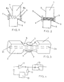
Fig. 1 is a schematic sectional view of an embodiment of the apparatus according to the invention. -
Fig. 2 is a corresponding view to that inFig. 1 but with the sound path illustrated. -
Fig. 3 is a schematic perspective view of an embodiment of the apparatus according to the invention, substantially corresponding to the embodiment shown inFigs. 1 and 2 . -
Fig. 4 is a schematic circuit diagram for electronic processing of the transducer signal from an apparatus according to the invention. - The bubble detection apparatus shown in
Figs. 1 to 3 is primarily intended to be used for the detection of air/liquid in passages for liquid chromatography, but it may, of course, also be used in other applications where gas bubbles (or other inhomogeneities) in a liquid flow are to be detected. The apparatus comprises a housing orcell body 1 provided with a liquid through-passage 2 with an inlet and anoutlet Fig. 3 ) designed to be connected to the liquid flow system in question. Thecell body 1 is suitably made in hard plastic, e.g. PEEK. The passage dimension (cross-sectional diameter) is for the contemplated liquid chromatography application typically in the range of 1 to 5 mm. Twoultrasonic transducers 3, 4, here discs of piezoelectric crystal - so-called piezotransducers - are mounted to the cell body opposite each other on either side of theliquid passage 2. As will be explained in more detail below, one transducer is used as sender and the other as receiver in cooperation with-an electronic control circuit. For best performance, the piezoelectric transducers are used at their resonance frequency, which depends inter alia on the thickness of the crystal disc. For a combination of two discs having a diameter of 5 mm and a thickness of 0.5 mm, for example, the resonance is at about 4 MHz. - In the embodiment shown in
Fig. 3 , the twotransducers 3, 4 are mounted to awaist portion 5 of the cell body in order to reduce the distance between the transducer and the liquid passage. - The
cell body 1 is further provided with two opposed cuts orrecesses recess 6 being provided between one transducer 3 and theliquid passage 2, and theother recess 7 being provided between theother transducer 4 and theliquid passage 2. Therecesses Figs. 1 and 2 to the level of the respective outer edge of thepassage 2, these outer edges being indicated bysight lines Fig. 1 . Together, the two vertically and horizontally opposedrecesses transducers 3, 4 follows a route which in the vertical direction inFigs. 1 and 2 essentially is restricted to the extension of the liquid passage. The sound path obtained is indicated inFig. 2 byreference numeral 9. As is readily seen, this shielding or guiding of the ultrasound results in that substantially all sound energy that is detected by the receiving transducer has passed through theliquid passage 2. From the viewpoint of sound guiding or shielding, it is, of course, advantageous if therecesses Figs. 1 and 2 extend essentially all the way from therespective transducer 3, 4 to thepassage 2, as shown inFigs. 1 and 2 . - Due to the fact that the two
recesses Figs. 1 and 2 , are positioned on different sides of theliquid passage 2, the cell body will maintain a considerable twisting or torsional strength. The material thickness around thepassage 2, and not least in thewaist portion 5 in the embodiment ofFig. 3 , is, of course, adjusted to the mechanical requirements for each specific application. Optionally, therecesses - As emphasized previously, the fact that the
liquid passage 2 dominates the area that the emitted ultrasound passes through the cell results in that a great and reliable difference between the respective sound intensities detected for liquid and gas, usually air, is obtained. This causes in turn that the electronic circuit that is necessary for driving the detector cell may be made very small. A schematic example of such a circuit is shown inFig. 4 . - In this circuit, the sending transducer of a detector cell of the type described above, here designated by
reference numeral 10, is connected to the input of anamplifier 11, while the receiver of thedetector cell 10 is connected to the output of the amplifier via aresistor 12. The amplifier output is also connected to anoutput driver stage 13 comprising a rectifier and a transistor. The magnitude of theresistor 12 is selected for adjusting the amplified cell detector signal to a desired level. The output signal from thedriver stage 13 is then conducted to a suitable display device, or is used as control signal in an automated system. - As appears from the above, the bubble detection apparatus described provides a robust unit which is suitable for small liquid passage dimensions, gives a reliable detection of air bubbles and only requires a simple control electronic circuitry simultaneously as it is easy to handle and manufacture (one-piece cell body).
- The invention is, of course, not restricted to the embodiments specifically described above and illustrated on the drawings but may be changed and modified in many ways within the general inventive concept as defined in the following claims.
Claims (5)
- An apparatus for detecting inhomogeneities, particularly gas bubbles, in a liquid flow, which apparatus comprises:a one-piece housing (1) of a material that is transmissive to ultrasound,a liquid passage (2) extending through the housing (1),inlet and outlet means (2a, 2b) on the housing (1) for connecting the liquid passage (2) to the liquid flow, andultrasonic transducer means (3, 4) on the housing on each side of the liquid passage (2), one transducer means being arranged as sender and the other transducer means being arranged as receiver, with the liquid passage (2) positioned in the sound transmission path between the sender and the receiver, whereby inhomogeneities in the liquid flow can be detected based on the emitted ultrasound energy that is received by the receiver,wherein the housing (1) has two opposed recesses (6, 7), one on the sender side of the liquid passage (2) and one on the receiver side thereof, which recesses in a direction perpendicular to the sound transmission path (9) as well as to the liquid passage (2) extend on opposite sides of the sound transmission path (9) substantially to the level of the respective outer edge (8a, 8b) of the liquid passage (2), and in the sound transmission direction extend from a respective transducer means (3, 4) towards the liquid passage (2) with the remaining housing portion between the recess and the other transducer means being unrecessed, in order that the recesses (6,7) together by shielding guide the ultrasound transmission between the sending transducer means and the receiving transducer means to take place substantially through the liquid passage (2).
- The apparatus according to claim 1, characterized in that the housing (1) is made of hard plastic.
- The apparatus according to claim 1 or 2, characterized in that the recesses (6, 7) are filled with a material of high acoustic impedance.
- A system for detecting inhomogeneities, particularly gas bubbles, in a liquid flow, characterized in that the system comprises an apparatus according to any one of claims 1 to 3, and an electric circuit for driving and signal processing.
- Use of an apparatus according to any one of claims 1 to 3, or of a system according to claim 4, for detecting air bubbles in liquid chromatography.
Applications Claiming Priority (3)
| Application Number | Priority Date | Filing Date | Title |
|---|---|---|---|
| SE9700853A SE9700853D0 (en) | 1997-03-10 | 1997-03-10 | Device for detecting inhomogeneities in a fluid flow |
| SE9700853 | 1997-03-10 | ||
| PCT/SE1998/000419 WO1998040733A1 (en) | 1997-03-10 | 1998-03-10 | Apparatus for detection of inhomogeneities in a liquid flow |
Publications (2)
| Publication Number | Publication Date |
|---|---|
| EP0966677A1 EP0966677A1 (en) | 1999-12-29 |
| EP0966677B1 true EP0966677B1 (en) | 2009-02-18 |
Family
ID=20406090
Family Applications (1)
| Application Number | Title | Priority Date | Filing Date |
|---|---|---|---|
| EP98909919A Expired - Lifetime EP0966677B1 (en) | 1997-03-10 | 1998-03-10 | Apparatus for detection of inhomogeneities in a liquid flow |
Country Status (8)
| Country | Link |
|---|---|
| US (1) | US6282949B1 (en) |
| EP (1) | EP0966677B1 (en) |
| JP (1) | JP4124490B2 (en) |
| AT (1) | ATE423307T1 (en) |
| DE (1) | DE69840569D1 (en) |
| ES (1) | ES2320821T3 (en) |
| SE (1) | SE9700853D0 (en) |
| WO (1) | WO1998040733A1 (en) |
Families Citing this family (14)
| Publication number | Priority date | Publication date | Assignee | Title |
|---|---|---|---|---|
| GB9921982D0 (en) * | 1999-09-16 | 1999-11-17 | Secretary Trade Ind Brit | Cavitation sensor |
| CA2415671C (en) * | 2000-07-13 | 2011-02-01 | Transurgical, Inc. | Energy application with inflatable annular lens |
| EP2275175B1 (en) * | 2000-07-13 | 2016-08-24 | ReCor Medical, Inc. | Thermal treatment apparatus with ultrasonic energy application |
| US6763722B2 (en) * | 2001-07-13 | 2004-07-20 | Transurgical, Inc. | Ultrasonic transducers |
| US20040082859A1 (en) | 2002-07-01 | 2004-04-29 | Alan Schaer | Method and apparatus employing ultrasound energy to treat body sphincters |
| WO2004073505A2 (en) | 2003-02-20 | 2004-09-02 | Prorhythm, Inc. | Cardiac ablation devices |
| EP2261742A3 (en) * | 2003-06-11 | 2011-05-25 | ASML Netherlands BV | Lithographic apparatus and device manufacturing method. |
| EP2021846B1 (en) | 2006-05-19 | 2017-05-03 | Koninklijke Philips N.V. | Ablation device with optimized input power profile |
| US7805978B2 (en) | 2006-10-24 | 2010-10-05 | Zevex, Inc. | Method for making and using an air bubble detector |
| AU2008279841B2 (en) * | 2007-07-25 | 2013-05-02 | Cytiva Bioprocess R&D Ab | Separation matrix |
| WO2010080886A1 (en) | 2009-01-09 | 2010-07-15 | Recor Medical, Inc. | Methods and apparatus for treatment of mitral valve in insufficiency |
| US9518958B2 (en) | 2012-12-18 | 2016-12-13 | Deka Products Limited Partnership | System, method, and apparatus for detecting air in a fluid line using active rectification |
| EP2372330B1 (en) * | 2010-03-31 | 2013-01-16 | LIFEBRIDGE Medizintechnik AG | Air bubble sensor |
| CN115219587A (en) * | 2022-07-15 | 2022-10-21 | 宁波艾纯生物科技有限公司 | Flow cell for bubble and/or particle detection, detector and device having the same |
Family Cites Families (9)
| Publication number | Priority date | Publication date | Assignee | Title |
|---|---|---|---|---|
| GB1418181A (en) * | 1973-02-27 | 1975-12-17 | Cole E M | Ultrasonic detection of inclusions in a fluid flowing within a tube |
| US3974681A (en) * | 1973-10-23 | 1976-08-17 | Jerry Namery | Ultrasonic bubble detector |
| US4015464A (en) * | 1975-02-21 | 1977-04-05 | The Washington University | Ultrasonic continuous wave particle monitor |
| US4418565A (en) * | 1980-12-03 | 1983-12-06 | Baxter Travenol Laboratories, Inc. | Ultrasonic bubble detector |
| JPS58131555A (en) * | 1982-01-29 | 1983-08-05 | Aisin Warner Ltd | Detection of characteristic of liquid by sound wave |
| US4607520A (en) * | 1984-01-09 | 1986-08-26 | Introtek Corporation | Method and apparatus for detecting discontinuities in a fluid stream |
| US4651555A (en) * | 1984-09-11 | 1987-03-24 | Introtek Corporation | Apparatus for detecting discontinuities in a fluid stream |
| US5394732A (en) * | 1993-09-10 | 1995-03-07 | Cobe Laboratories, Inc. | Method and apparatus for ultrasonic detection of air bubbles |
| DE4435594C2 (en) * | 1994-10-05 | 1996-08-14 | Hans Rattay | Method for detecting in particular lines transporting gas in liquid media and device for carrying out the method |
-
1997
- 1997-03-10 SE SE9700853A patent/SE9700853D0/en unknown
-
1998
- 1998-03-10 DE DE69840569T patent/DE69840569D1/en not_active Expired - Lifetime
- 1998-03-10 US US09/380,108 patent/US6282949B1/en not_active Expired - Lifetime
- 1998-03-10 AT AT98909919T patent/ATE423307T1/en not_active IP Right Cessation
- 1998-03-10 JP JP53951298A patent/JP4124490B2/en not_active Expired - Fee Related
- 1998-03-10 WO PCT/SE1998/000419 patent/WO1998040733A1/en not_active Ceased
- 1998-03-10 EP EP98909919A patent/EP0966677B1/en not_active Expired - Lifetime
- 1998-03-10 ES ES98909919T patent/ES2320821T3/en not_active Expired - Lifetime
Also Published As
| Publication number | Publication date |
|---|---|
| JP2001514754A (en) | 2001-09-11 |
| SE9700853D0 (en) | 1997-03-10 |
| US6282949B1 (en) | 2001-09-04 |
| DE69840569D1 (en) | 2009-04-02 |
| JP4124490B2 (en) | 2008-07-23 |
| WO1998040733A1 (en) | 1998-09-17 |
| EP0966677A1 (en) | 1999-12-29 |
| ES2320821T3 (en) | 2009-05-28 |
| ATE423307T1 (en) | 2009-03-15 |
Similar Documents
| Publication | Publication Date | Title |
|---|---|---|
| US6282949B1 (en) | Apparatus for detection of inhomogeneities in a liquid flow | |
| US4418565A (en) | Ultrasonic bubble detector | |
| EP2126557B1 (en) | Ultrasonic system for detecting and quantifying of air bubbles/particles in a flowing liquid | |
| JP3749260B2 (en) | Device for controlling the flow of liquid in a line, in particular a peristaltic pump | |
| US3974681A (en) | Ultrasonic bubble detector | |
| US5123275A (en) | Air in-line sensor system | |
| KR100877441B1 (en) | Surgical system with cassette with sonic connection | |
| US4015464A (en) | Ultrasonic continuous wave particle monitor | |
| US6068599A (en) | Blood vessel puncturing device using ultrasound | |
| RU2489171C2 (en) | Surgical cartridge with acoustic air screen | |
| JP4782327B2 (en) | Clamp-on type ultrasonic flowmeter | |
| US4063457A (en) | Ultrasonic level sensing device | |
| CA2645255C (en) | Non-invasive flow measurement | |
| EP0536313A4 (en) | Improved flow measurement system | |
| EP2440889B1 (en) | Ultrasonic fluid flow meter housing with acoustically matched base | |
| US4279167A (en) | Liquid coupling for doppler sonic flowmeter | |
| US20020104370A1 (en) | Ultrasonic sensor for detecting gas bubbles | |
| US20240125635A1 (en) | Ultrasonic flowmeter | |
| US20120031199A1 (en) | Ultrasonic liquid sensor apparatus and system | |
| CN208355529U (en) | A kind of electromagnetic sound formula bone surgery guiding device | |
| JPH03259718A (en) | Flow velocity measuring instrument | |
| JPH07280626A (en) | Ultrasonic liquid level indicator | |
| JPH0778444B2 (en) | Ultrasonic detector | |
| JPH11211539A (en) | Liquid level detection method in high pressure vessel |
Legal Events
| Date | Code | Title | Description |
|---|---|---|---|
| PUAI | Public reference made under article 153(3) epc to a published international application that has entered the european phase |
Free format text: ORIGINAL CODE: 0009012 |
|
| 17P | Request for examination filed |
Effective date: 19991007 |
|
| AK | Designated contracting states |
Kind code of ref document: A1 Designated state(s): AT BE CH DE DK ES FI FR GB IE IT LI LU NL SE |
|
| RAP1 | Party data changed (applicant data changed or rights of an application transferred) |
Owner name: AMERSHAM BIOSCIENCES AB |
|
| RAP1 | Party data changed (applicant data changed or rights of an application transferred) |
Owner name: GE HEALTHCARE BIO-SCIENCES AB |
|
| 17Q | First examination report despatched |
Effective date: 20061103 |
|
| GRAP | Despatch of communication of intention to grant a patent |
Free format text: ORIGINAL CODE: EPIDOSNIGR1 |
|
| GRAS | Grant fee paid |
Free format text: ORIGINAL CODE: EPIDOSNIGR3 |
|
| GRAA | (expected) grant |
Free format text: ORIGINAL CODE: 0009210 |
|
| AK | Designated contracting states |
Kind code of ref document: B1 Designated state(s): AT BE CH DE DK ES FI FR GB IE IT LI LU NL SE |
|
| REG | Reference to a national code |
Ref country code: GB Ref legal event code: FG4D |
|
| REG | Reference to a national code |
Ref country code: CH Ref legal event code: EP |
|
| REG | Reference to a national code |
Ref country code: CH Ref legal event code: NV Representative=s name: ISLER & PEDRAZZINI AG |
|
| REG | Reference to a national code |
Ref country code: IE Ref legal event code: FG4D |
|
| REF | Corresponds to: |
Ref document number: 69840569 Country of ref document: DE Date of ref document: 20090402 Kind code of ref document: P |
|
| REG | Reference to a national code |
Ref country code: ES Ref legal event code: FG2A Ref document number: 2320821 Country of ref document: ES Kind code of ref document: T3 |
|
| PG25 | Lapsed in a contracting state [announced via postgrant information from national office to epo] |
Ref country code: FI Free format text: LAPSE BECAUSE OF FAILURE TO SUBMIT A TRANSLATION OF THE DESCRIPTION OR TO PAY THE FEE WITHIN THE PRESCRIBED TIME-LIMIT Effective date: 20090218 |
|
| PG25 | Lapsed in a contracting state [announced via postgrant information from national office to epo] |
Ref country code: AT Free format text: LAPSE BECAUSE OF FAILURE TO SUBMIT A TRANSLATION OF THE DESCRIPTION OR TO PAY THE FEE WITHIN THE PRESCRIBED TIME-LIMIT Effective date: 20090218 |
|
| PG25 | Lapsed in a contracting state [announced via postgrant information from national office to epo] |
Ref country code: BE Free format text: LAPSE BECAUSE OF FAILURE TO SUBMIT A TRANSLATION OF THE DESCRIPTION OR TO PAY THE FEE WITHIN THE PRESCRIBED TIME-LIMIT Effective date: 20090218 |
|
| PG25 | Lapsed in a contracting state [announced via postgrant information from national office to epo] |
Ref country code: DK Free format text: LAPSE BECAUSE OF FAILURE TO SUBMIT A TRANSLATION OF THE DESCRIPTION OR TO PAY THE FEE WITHIN THE PRESCRIBED TIME-LIMIT Effective date: 20090218 |
|
| PLBE | No opposition filed within time limit |
Free format text: ORIGINAL CODE: 0009261 |
|
| STAA | Information on the status of an ep patent application or granted ep patent |
Free format text: STATUS: NO OPPOSITION FILED WITHIN TIME LIMIT |
|
| 26N | No opposition filed |
Effective date: 20091119 |
|
| PG25 | Lapsed in a contracting state [announced via postgrant information from national office to epo] |
Ref country code: IE Free format text: LAPSE BECAUSE OF NON-PAYMENT OF DUE FEES Effective date: 20090310 |
|
| PG25 | Lapsed in a contracting state [announced via postgrant information from national office to epo] |
Ref country code: LU Free format text: LAPSE BECAUSE OF NON-PAYMENT OF DUE FEES Effective date: 20090310 |
|
| PGFP | Annual fee paid to national office [announced via postgrant information from national office to epo] |
Ref country code: CH Payment date: 20110325 Year of fee payment: 14 Ref country code: SE Payment date: 20110329 Year of fee payment: 14 Ref country code: IT Payment date: 20110328 Year of fee payment: 14 Ref country code: FR Payment date: 20110331 Year of fee payment: 14 Ref country code: NL Payment date: 20110329 Year of fee payment: 14 |
|
| PGFP | Annual fee paid to national office [announced via postgrant information from national office to epo] |
Ref country code: ES Payment date: 20110328 Year of fee payment: 14 |
|
| REG | Reference to a national code |
Ref country code: NL Ref legal event code: V1 Effective date: 20121001 |
|
| REG | Reference to a national code |
Ref country code: SE Ref legal event code: EUG |
|
| PG25 | Lapsed in a contracting state [announced via postgrant information from national office to epo] |
Ref country code: SE Free format text: LAPSE BECAUSE OF NON-PAYMENT OF DUE FEES Effective date: 20120311 |
|
| REG | Reference to a national code |
Ref country code: CH Ref legal event code: PL |
|
| REG | Reference to a national code |
Ref country code: DE Ref legal event code: R082 Ref document number: 69840569 Country of ref document: DE Representative=s name: J D REYNOLDS & CO., GB |
|
| REG | Reference to a national code |
Ref country code: FR Ref legal event code: ST Effective date: 20121130 |
|
| PG25 | Lapsed in a contracting state [announced via postgrant information from national office to epo] |
Ref country code: FR Free format text: LAPSE BECAUSE OF NON-PAYMENT OF DUE FEES Effective date: 20120402 Ref country code: LI Free format text: LAPSE BECAUSE OF NON-PAYMENT OF DUE FEES Effective date: 20120331 Ref country code: CH Free format text: LAPSE BECAUSE OF NON-PAYMENT OF DUE FEES Effective date: 20120331 |
|
| PG25 | Lapsed in a contracting state [announced via postgrant information from national office to epo] |
Ref country code: IT Free format text: LAPSE BECAUSE OF NON-PAYMENT OF DUE FEES Effective date: 20120310 |
|
| PG25 | Lapsed in a contracting state [announced via postgrant information from national office to epo] |
Ref country code: NL Free format text: LAPSE BECAUSE OF NON-PAYMENT OF DUE FEES Effective date: 20121001 |
|
| REG | Reference to a national code |
Ref country code: ES Ref legal event code: FD2A Effective date: 20130710 |
|
| PG25 | Lapsed in a contracting state [announced via postgrant information from national office to epo] |
Ref country code: ES Free format text: LAPSE BECAUSE OF NON-PAYMENT OF DUE FEES Effective date: 20120311 |
|
| PGFP | Annual fee paid to national office [announced via postgrant information from national office to epo] |
Ref country code: GB Payment date: 20140327 Year of fee payment: 17 |
|
| PGFP | Annual fee paid to national office [announced via postgrant information from national office to epo] |
Ref country code: DE Payment date: 20140327 Year of fee payment: 17 |
|
| REG | Reference to a national code |
Ref country code: DE Ref legal event code: R119 Ref document number: 69840569 Country of ref document: DE |
|
| GBPC | Gb: european patent ceased through non-payment of renewal fee |
Effective date: 20150310 |
|
| PG25 | Lapsed in a contracting state [announced via postgrant information from national office to epo] |
Ref country code: DE Free format text: LAPSE BECAUSE OF NON-PAYMENT OF DUE FEES Effective date: 20151001 Ref country code: GB Free format text: LAPSE BECAUSE OF NON-PAYMENT OF DUE FEES Effective date: 20150310 |