EP0966616B1 - Vorrichtung und verfahren zur wartung eines automatischen getriebes - Google Patents
Vorrichtung und verfahren zur wartung eines automatischen getriebes Download PDFInfo
- Publication number
- EP0966616B1 EP0966616B1 EP98910250A EP98910250A EP0966616B1 EP 0966616 B1 EP0966616 B1 EP 0966616B1 EP 98910250 A EP98910250 A EP 98910250A EP 98910250 A EP98910250 A EP 98910250A EP 0966616 B1 EP0966616 B1 EP 0966616B1
- Authority
- EP
- European Patent Office
- Prior art keywords
- fluid
- atf
- transmission
- pump
- machine
- Prior art date
- Legal status (The legal status is an assumption and is not a legal conclusion. Google has not performed a legal analysis and makes no representation as to the accuracy of the status listed.)
- Expired - Lifetime
Links
- 230000005540 biological transmission Effects 0.000 title claims abstract description 164
- 238000000034 method Methods 0.000 title claims description 26
- 239000012530 fluid Substances 0.000 claims abstract description 177
- 239000002699 waste material Substances 0.000 claims description 10
- 230000000694 effects Effects 0.000 claims description 7
- 238000004891 communication Methods 0.000 claims description 6
- 238000006073 displacement reaction Methods 0.000 claims description 5
- 238000005086 pumping Methods 0.000 claims description 4
- 238000011010 flushing procedure Methods 0.000 description 7
- 238000007789 sealing Methods 0.000 description 4
- 238000003860 storage Methods 0.000 description 4
- 230000007812 deficiency Effects 0.000 description 3
- 230000005484 gravity Effects 0.000 description 3
- 238000004140 cleaning Methods 0.000 description 2
- 238000010276 construction Methods 0.000 description 2
- 239000002826 coolant Substances 0.000 description 2
- 230000007935 neutral effect Effects 0.000 description 2
- 238000004064 recycling Methods 0.000 description 2
- 238000009987 spinning Methods 0.000 description 2
- OKTJSMMVPCPJKN-UHFFFAOYSA-N Carbon Chemical group [C] OKTJSMMVPCPJKN-UHFFFAOYSA-N 0.000 description 1
- 230000004075 alteration Effects 0.000 description 1
- 239000012809 cooling fluid Substances 0.000 description 1
- 230000001419 dependent effect Effects 0.000 description 1
- 238000005516 engineering process Methods 0.000 description 1
- 238000001914 filtration Methods 0.000 description 1
- 239000011521 glass Substances 0.000 description 1
- 238000001802 infusion Methods 0.000 description 1
- 238000002156 mixing Methods 0.000 description 1
- 238000009428 plumbing Methods 0.000 description 1
- 238000002360 preparation method Methods 0.000 description 1
- 230000000750 progressive effect Effects 0.000 description 1
- 239000000126 substance Substances 0.000 description 1
- 239000002966 varnish Substances 0.000 description 1
Images

Classifications
-
- F—MECHANICAL ENGINEERING; LIGHTING; HEATING; WEAPONS; BLASTING
- F02—COMBUSTION ENGINES; HOT-GAS OR COMBUSTION-PRODUCT ENGINE PLANTS
- F02B—INTERNAL-COMBUSTION PISTON ENGINES; COMBUSTION ENGINES IN GENERAL
- F02B77/00—Component parts, details or accessories, not otherwise provided for
- F02B77/04—Cleaning of, preventing corrosion or erosion in, or preventing unwanted deposits in, combustion engines
-
- F—MECHANICAL ENGINEERING; LIGHTING; HEATING; WEAPONS; BLASTING
- F01—MACHINES OR ENGINES IN GENERAL; ENGINE PLANTS IN GENERAL; STEAM ENGINES
- F01M—LUBRICATING OF MACHINES OR ENGINES IN GENERAL; LUBRICATING INTERNAL COMBUSTION ENGINES; CRANKCASE VENTILATING
- F01M11/00—Component parts, details or accessories, not provided for in, or of interest apart from, groups F01M1/00 - F01M9/00
- F01M11/04—Filling or draining lubricant of or from machines or engines
- F01M11/0458—Lubricant filling and draining
-
- F—MECHANICAL ENGINEERING; LIGHTING; HEATING; WEAPONS; BLASTING
- F16—ENGINEERING ELEMENTS AND UNITS; GENERAL MEASURES FOR PRODUCING AND MAINTAINING EFFECTIVE FUNCTIONING OF MACHINES OR INSTALLATIONS; THERMAL INSULATION IN GENERAL
- F16H—GEARING
- F16H57/00—General details of gearing
- F16H57/04—Features relating to lubrication or cooling or heating
- F16H57/0408—Exchange, draining or filling of transmission lubricant
-
- F—MECHANICAL ENGINEERING; LIGHTING; HEATING; WEAPONS; BLASTING
- F01—MACHINES OR ENGINES IN GENERAL; ENGINE PLANTS IN GENERAL; STEAM ENGINES
- F01M—LUBRICATING OF MACHINES OR ENGINES IN GENERAL; LUBRICATING INTERNAL COMBUSTION ENGINES; CRANKCASE VENTILATING
- F01M11/00—Component parts, details or accessories, not provided for in, or of interest apart from, groups F01M1/00 - F01M9/00
- F01M11/04—Filling or draining lubricant of or from machines or engines
-
- F—MECHANICAL ENGINEERING; LIGHTING; HEATING; WEAPONS; BLASTING
- F01—MACHINES OR ENGINES IN GENERAL; ENGINE PLANTS IN GENERAL; STEAM ENGINES
- F01M—LUBRICATING OF MACHINES OR ENGINES IN GENERAL; LUBRICATING INTERNAL COMBUSTION ENGINES; CRANKCASE VENTILATING
- F01M11/00—Component parts, details or accessories, not provided for in, or of interest apart from, groups F01M1/00 - F01M9/00
- F01M11/04—Filling or draining lubricant of or from machines or engines
- F01M11/0458—Lubricant filling and draining
- F01M2011/0466—Filling or draining during running
Definitions
- the present invention is in the field of apparatus and method used to effect exchange of fluid from a system of an automobile.
- the apparatus and method may be used to change automatic transmission fluid (ATF) from an automotive automatic transmission.
- ATF automatic transmission fluid
- the apparatus and method may also be used to change power steering fluid from an automotive power steering system.
- the present invention relates to a fail-safe machine and to a method of its operation and use in exchanging the used ATF of an automatic transmission with fresh ATF, or in exchanging used power steering fluid with fresh fluid, and which is very economical in its construction, energy efficient in its operation, environmentally responsible, and uniquely easy to use for the automotive technician.
- This operation of the vehicle engine is usually accomplished on a chassis roller set allowing the drive wheels to spin and the clutches of the transmission to be cycled. Operation of the vehicle engine powers the internal fluid pump of the transmission and also facilitates flow of ATF through the torque converter and other parts of the transmission system, effectively flushing out the old ATF and replacing it with new fluid.
- the vehicle engine can be run with the transmission in "neutral” or “park”, with most of the old ATF being exchanged in this way (i.e., without the drive wheels spinning or the transmission clutches being cycled). In this latter case, the old ATF will still be flushed from the torque converter, ATF cooler, and connecting conduits of the transmission system.
- this operation of the vehicle engine creates a risk that the transmission can be damaged or destroyed by dry running. That is, if the old transmission fluid is drained out, and the transmission is not simultaneously refilled with sufficient new fluid so that the fluid level in the transmission drops too low, then the transmission can be damaged by dry running.
- the old ATF is drained out by opening an ATF cooler connection conduit while the vehicle engine is running, and infusing new ATF at the fill tube of the transmission only when bubbles of air are observed to drain also with the ATF from the transmission. These bubbles are an indication that the fluid level of the transmission is low enough that its internal pump is drawing air. AT this time, a dose of new transmission fluid is added via the fill tube of the transmission.
- the new transmission fluid may be allowed to partially or completely drain out (perhaps while the attendant is distracted or absent for some reason), and the transmission can be damaged.
- this method requires the full-time attention of two attendants - one to watch the draining ATF and signal the presence of bubbles, and one to infuse new ATF at the fill tube in response to a signal from the first attendant. Obviously, this method is both labor intensive and prone to error.
- an external power failure to the transmission service machine may occur during the service process, with the vehicle under service still running. This may result in the vehicle running without sufficient ATF in the transmission or with its external transmission cooler loop open and the fluid from the transmission being pumped to waste. Again, transmission damage can result unless the attendant catches this situation early enough.
- a cleaning machine for an automotive automatic transmission is known according to United States patent No. 5,337,708, showing all of the features of the preamble of each of the claims 1 and 6.
- the '708 patent is believed to teach a transmission fluid change machine in which an external ATF circulation loop of the transmission is opened, with part of the machine completing this loop in one mode of operation.
- the used transmission fluid possibly with a transmission flushing solution, is circulated in the external circulation loop as completed by the machine.
- the machine When operated in an exchange/refill mode, the machine receives old transmission fluid and supplies new fluid at a selected pressure or volume delivery rate.
- the Chen machine is intended to be operated from the 12 volt power supply of the automobile or other automotive vehicle being serviced.
- the new transmission fluid tank of this device appears to be provided with a level sensor, so that the system can be reverted to loop configuration (filtration/flushing) should the level of new ATF drop too low.
- An external power-driven pump is utilized to move new ATF from the fluid tank to the transmission being serviced.
- the configuration of the device is reverted to loop form so that the transmission of the vehicle being serviced is not damaged by being operated with insufficient ATF.
- this patent asserts that a power failure will cause reversion of the apparatus to loop configuration in the event of a power failure, how this change in configuration is to be effected or powered does not appear to be explained.
- Air displaced from the one container is routed into the other with the idea that the air will drive the new ATF into the transmission.
- a pressurized air assist to this delivery of new fluid is provided.
- the rate of new fluid delivery really matches the rate of old fluid draining from the transmission under service.
- a transmission service machine is also known according to United States patent No. 5,370,160, issued 6 December 1994 to Zachary T. Parker.
- the '160 patent is believed to disclose a service machine in which the external ATF fluid return loop for the transmission is completed by a reservoir from which the fluid is drawn by a pump. Accordingly, in the event that operation of the pump is interrupted while the serviced vehicle continues to operate, the transmission of the vehicle is at risk of damage from dry running.
- a separate pump is used to supply new ATF to the transmission, but this pump may suffer from the same power supply interruption, so that the transmission is still at risk of damage from dry running.
- the Parker '160 patent does not appear to provide a closed external ATF circulation loop for the transmission being serviced (other than the one relying on operation of an external power-driven pump), and does not use a three-way valve to complete or open such an external ATF circulation loop.
- Still another apparatus for exchanging the fluid of an automatic transmission is known in accord with United States patent No. 5,447,184, issued 5 September 1995 to Eduardo Betancourt.
- the '184 patent is believed to disclose an apparatus in which a reservoir for new ATF is provided so that the volume of new fluid supplied to the transmission can exceed the withdrawn volume.
- the '184 patent appears to include a sensor operating a bell to bring the attendant's attention to the fact that the supply of new ATF is at risk of running out. However, if the attendant is either not close at hand to hear the bell or is inattentive, the transmission may still be damaged if the supply of new ATF runs out while the transmission is being flushed. Still further, the device taught by the '184 patent is not believed to provide any safeguard to protect the automatic transmission in the event of a power failure to the apparatus while the transmission is being flushed during operation.
- a primary object for this invention is to avoid one or more of these deficiencies.
- Another object is to provide a fail-safe automatic transmission service machine.
- Yet another object is to provide a machine for exchanging old fluid with fresh fluid in an automotive power steering system.
- the present invention defined by claim 1 provides a method of exchanging used ATF with new ATF in an automotive automatic transmission having an internal pump and an external fluid circulation loop, and without limitation on the volume of ATF which can be exchanged, the method comprising steps of providing a source of new ATF; connecting a positive displacement motor/pump unit into the external fluid circulation loop, so that the loop is opened and old ATF from the transmission flows via a motor portion of the motor/pump unit to waste by reason of pressure provided by the internal transmission pump and drives the pump portion of the motor/pump unit, and flowing new ATF from the source through the pump portion of the motor/pump unit to the automatic transmission so as to effect a pseudo-closing of the external fluid circulation loop, whereby used ATF pumped out of the transmission by the internal pump is continuously replaced in equal volume with new ATF from the source by the motor/pump unit.
- a fail-safe transmission fluid exchange machine in particular for an automotive automatic transmission, which automatic transmission includes an internal pump moving automatic transmission fluid (ATF) through an external circulation loop, the machine comprising: a first conduit for conducting ATF from the external ATF circulation loop, a three-way valve in a first position communicating ATF received via the first conduit from the external circulation loop to a second conduit, which second conduit returns ATF to the external ATF circulation loop, the three-way valve in a second position thereof communicating ATF from the external ATF circulation loop to waste; a yieldably-biased back-drivable actuator which when actuated moves the three-way valve from the first to the second position thereof and which when deactivated returns the three-way valve to the first position by self-bias; a container for holding a supply of new ATF; a sensor for indicating when the container holds an adequate supply of new ATF; a pump receiving new ATF from the container therefor and supplying the new ATF pressurized via the second conduit to the external
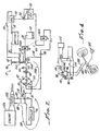
- Figure 1 provides a fragmentary pictorial and somewhat schematic depiction of an automobile having its automatic transmission serviced by a machine embodying the present invention
- Figure 2 is a schematic representation of automobile power (engine and transmission) as well as the transmission service machine seen in Figure 1, and depicts alternative modes of operation (or fluid flow paths) utilized during the servicing of the transmission;
- FIG 3 provides a perspective view of a motor/pump unit used in the transmission service machine seen in Figures 1 and 2, and is shown with the housing of this motor/pump illustrated in phantom lines for improved clarity of description; and
- Figures 4 provides a schematic representation of an automotive power steering system, during servicing to exchange old fluid with fresh fluid using a machine and method according to the present invention.
- an automotive vehicle 10 having its automatic transmission serviced by use of a fail-safe machine 12 embodying the present invention. It will be understood that the vehicle 10 is illustrative only, and that other types of automotive vehicles may have their transmissions serviced by use of the machine 12. For example, some heavy trucks and busses use automatic transmissions, which also may be serviced in the way described below.
- the machine 12 is connected to the vehicle 10 in two respects.
- the machine 12 is connected by a pair of hoses 14 and 16 to the transmission cooling fluid circuit of the vehicle 10, as will be explained.
- the machine 12 is electrically connected in this case by a cable 18 to receive electrical power from the vehicle 10.
- the cable attaches by clamps to the appropriate terminals of the vehicle battery.
- the machine 12 requires no line power (i.e., no 110 volt or 220 volt AC power, for example), and uses only a small current of electrical power from the vehicle 10 to operate a fail-safe function of the machine.
- an alternative embodiment of the machine 12 can be provided which does not even require this electrical connection to the vehicle 10, and in which the machine 12 operates without any external electrical power input.
- the machine 12 includes a cabinet 20 having wheels 22 and a handle 24 providing for the cabinet to be rolled about a service area, for example, to an appropriate position next to a vehicle to be serviced.
- the machine 12 will be seen to have a very low center of gravity so that it is easily tipped for moving and is stable both while stationary and during such moving on its wheels about a service area.
- Such low center of gravity is provided by the machine 12 because essentially the entire lower portion 28 of the cabinet defines a reservoir for new transmission fluid, providing an exceptionally low center of gravity for the machine 12.
- the front of the machine 12 is provided with a vertically extending sight glass 28a (actually formed of break-resistant plastic tubing) providing an indication of the fluid level in the reservoir portion 28 of the machine 12.
- AFT exchange mode of operation used ATF flows from the transmission to machine 12, and then to a container 32 via a hose 34 for recycling or appropriate disposal.
- the hose 34 may simply be routed to a large used-fluid storage tank maintained by some service facilities for this purpose. The service area in this case will have access to many conveniently located inlets to this storage tank, and the container 32 will not be needed.
- new ATF is supplied by the machine 12 from the reservoir 28 into the transmission of the vehicle via hose 16. While this AFT exchange process is going on the fluid flow rates in the hoses 14 and 16 are substantially matched to one another by the machine 12. Accordingly, the fluid level in the transmission of the vehicle 10 can not drop too low, and transmission damage from dry running can not occur.
- the machine 12 will either not enter exchange mode, or will automatically revert from this mode to flush (i.e., recirculation) mode. Again, dry running of the vehicle transmission can not occur. Also, in the event that power to the machine 12 is interrupted (i.e., if one of the clamps 18a becomes disconnected, for example), then the machine 12 reverts instantly to flush mode without the need for manual attention from an attendant and without power being required to effect this reversion to flush mode.
- the cooler 36 is connected in fluid flow to the transmission 10b by conduits 38 and 40, with ATF flow directions in these conduits being indicated by the arrows on Figure 2.
- the conduits 38, 40, and cooler 36 cooperatively define an external closed ATF circulation loop for the transmission 10b, which external closed fluid circulation loop is indicated by numeral 39 on Figure 2.
- Conduit 38 is shown in Figure 2 with a portion of its length depicted in dashed line.
- the dashed line portion of conduit 38 is connected together, and fluid flows from the transmission to the cooler 36 along this conduit.
- one of the conduits 38 or 40 is interrupted as suggested in Figure 2, and the machine 12 is connected into the previously-closed ATF circulation loop 39 for cooler 36.
- conduit 38 is the one shown opened for connection of machine 12.
- either of the conduits 38 or 40 may be so opened, dependent upon which one is most easily accessible to the service technician on each particular individual vehicle to be serviced.
- Either of conduits 38 or 40 may be accessed for service of the transmission with absolutely no difference in the effectiveness of the service performed.
- the accessed one of the conduits 38 or 40 is interrupted, and after the service is complete the connection of the conduit is restored to its original fluid flow continuity.
- Machine 12 includes a fluid-flow rectifier assembly, indicated with numeral 42.
- This rectifier assembly includes four nodes (or fluid flow confluences and branchings) respectively indicated with numerals 44, 46, 48, and 50; and also includes four check valves each indicated with a respective numeral 52.
- the check valves 52 are each disposed between a connected pair of the nodes 44-50, and are oriented as shown in Figure 2. As is seen in Figure 2, hose 14 connects to node 44, and the hose 16 connects to node 50.
- the check valves 52 are each oriented so that fluid can flow only to node 48 and only away from node 46.
- ATF flow is always from one of nodes 44 or 50 to node 48, and from the other one of nodes 44 and 50 to node 46.
- Node 48 is connected by a conduit 52 including a pressure gauge 54 and a flow meter 68 to the common port of a spring-loaded three-way solenoid valve 56.
- the flow meter 68 has a visible indicator 68a of fluid flow, which is displayed on the front of machine 12, as is seen in Figure 1.
- the solenoid valve 56 has a normally-open (N.O.) port from which a conduit 58 connects to node 46. Accordingly, a closed loop fluid flow connection is provided by machine 12 which completes loop 39.
- This loop within machine 12 is indicated on Figure 2 with two loop arrows referenced with numerals 39a and 39b.
- the machine 12 completes the circulation loop 39 by flow of ATF in the internal loop indicated with numerals 39a and 39b of Figure 2.
- the service technician can observe the available pressure provided by the internal pump of the transmission 10b at gauge 54, seen on the front of machine 12 in Figure 1.
- this solenoid valve includes a valve portion 56a and a solenoid actuator portion 56b.
- the solenoid actuator portion 56b includes an armature member movably disposed within a solenoid coil 60, and a spring 62 biasing the armature toward a first position.
- the armature member interacts with the valve portion 56a so-that when the armature is in its first position the common port is connected only to the N.O. port of the valve portion 56a.
- armature member is moved to a second position (not shown) in which the common port of the valve portion 56b is connected only to the N.C. port of this valve portion.
- solenoid valve 56 connects via a conduit 64 to one portion (a motor portion) of a motor/pump unit 66. From this motor portion (indicated with numeral 66a), fluid flows via a hose 34 to the waste-fluid container 32.
- the machine 12 is also provided with a float switch 70 at reservoir 28, which electrically allows connection of the common port of solenoid valve 56 to the N.C. port only if a sufficient volume of new ATF is in this reservoir, and which closes if the level of this new ATF falls too low.
- Float switch 70 controls a relay 72 in circuit with the switch 30, solenoid coil 60, and the battery of the vehicle 10 via cable 18.
- solenoid coil 60 is actuated if relay 72 allows (i.e., if the float switch 70 indicates a sufficient level of new ATF in the reservoir 28), and the common port of solenoid valve 56 is switched from communication with the N.O. port to communication to the N.C. port.
- the internal closed ATF circulation loop of the machine 12 (recalling arrows 39a and 39b) is opened, and used ATF from the transmission 10b flows to waste container 32.
- the motor/pump unit 66 includes a housing 74 defining an inlet port 74a and outlet port 74b from motor portion 66a. Similarly, the housing 74 defines an inlet port 74c and outlet port 74d to and from a pump portion 66b.
- the motor portion 66a and pump portion 66b are each defined by a meshed pair of spur gears (respectively indicated with numerals 76, 78, 80, and 82.
- the housing 74 defines closely fitted chambers for these meshed gears, which is conventional in the art of spur-gear pumps and motors. However, in this case, the housing 74 also journals a pair of connecting shafts, indicated with numerals 84 and 86.
- the shafts 84 and 86 drivingly connect the indicated spur gears for rotation in unison, as is indicated by the arrows on Figure 3.
- ATF flows through the motor portion 66a (from port 74a to port 74b) of motor/pump unit 66 the gears 76 and 78 are forced to rotate as indicated, driving the gears 80 and 82 in rotation via shafts 84 and 86.
- the motor/pump unit 66 is a positive-displacement fluid motor/pump unit, with each side having identically the same fluid displacement per rotation of the gears 76-82 (ignoring some slight and insignificant volume of fluid which may leak from the motor portion to the pump portion of the unit).
- the housing 74 carries a pair of elongate plain journal bearings 88 (only a portion of each being seen in Figure 3 for clarity of illustration). These journal bearings 88 are closely and precisely fitted to the shafts 84 and 86 so that these shafts (and the gears 76-82) are very free running. Importantly, the close fitting of these journal bearings and shafts is relied upon to effect a sufficient fluid seal between the motor side and pump side of the motor/pump 66 so that only an insignificantly small amount of ATF flows along the shafts 84, 86 without the use of a contact type of sealing element.
- This may take the form of, for example, a carbon ring face seal, or a low-friction radial lip seal disposed between the housing 74 and each of the shafts 84, 86.
- the motor/pump unit 66 can achieve motoring and pumping operation utilizing only a relatively low fluid pressure provided by the internal pump of transmission 10b. This makes transmission servicing possible even with the engine 10a idling.
- the circulation loop 39 of the transmission is complete during flush mode and appears to be complete during exchange mode also, but new ATF is being supplied by the machine 12 in response to and in matching volume to the pumping out of old ATF by the transmission 10b during exchange mode.
- the technician can verify that fluid is flowing by observing the indicator 68a of flow meter 68.
- this flow meter is a turbine type with a transparent wall though which the technician can not only seen the spinning turbine, but can also observe the color and turbidity of the ATF flowing from the transmission to waste (i.e., this is visible on the front of machine 12 as seen in Figure 1).
- the technician knows that the flushing and fluid exchanging operation is complete.
- the technician disconnects the machine 12 at the connections to one of the conduits 38 or 40, restores the circulation loop 39, and sends the old transmission fluid for disposal or to a recycling facility.
- Figure 4 schematically illustrates an alternative embodiment of the present invention, in which a machine is used to service the power steering system of a vehicle to exchange old fluid from the system with new fluid.
- a machine is used to service the power steering system of a vehicle to exchange old fluid from the system with new fluid.
- reference numerals for use in describing this alternative embodiment of the invention, features which are either the same as those depicted and described above, or which are analogous in structure or function, are referenced in Figure 4 using the same numeral used above, and having one-hundred (100) added.
- a vehicle includes an engine driving a power steering pump 92 by means of a belt 94.
- This pump 92 includes a reservoir portion 96 disposed generally above the pump 92.
- the reservoir portion 96 has a fill opening 98 closed by a cap 100.
- a low-pressure hose 140 connects onto a fitting on the body of the reservoir portion 96 in order to allow return of low pressure power steering fluid into this reservoir.
- the pump 92 draws power steering fluid from the reservoir portion 96, and delivers this fluid pressurized via a high-pressure hose or conduit 138 to a power steering unit 102.
- the power steering unit 102 is connected to the dirigible wheels of the vehicle, and has a steering input from a steering wheel 104.
- the low pressure hose 140 is interrupted or disconnected at its connection to the fitting at reservoir portion 96. This disconnection of the hose 140 allows it to be connected to one of the hoses 114 or 116 of the machine 112.
- hose 114 or hose 116 may be connected to receive low-pressure power steering fluid from the system as depicted.
- the other hose 114 or 116 from machine 112 is either attached to the fitting on the reservoir 96 from which hose 140 was disconnected, or is simply routed so as to deliver fluid into the reservoir 96 via fill opening 98.
- the pump 92 when the engine 110a is operated, the pump 92 is powered and delivers high-pressure power steering fluid to the unit 102.
- Power steering fluid at a lower pressure flows from the unit 102 via hose 140, but is routed to machine 112 rather than flowing into reservoir 96.
- This power steering fluid is routed to machine 112, where it powers a motor/pump unit as described above.
- the machine 112 is provided with a source of new power steering fluid, which will be easily understood in view of the description above of providing machine 12 with a source of automatic transmission fluid.
- the motor/pump unit of the machine 112 delivers new power steering fluid at a matching volume rate to the reservoir 96 of the pump 92 via hose 116.
- hoses 114, and 116 can be reversed in function, as will be appreciated in view of the operation of the hydraulic rectifier of machine 12 as described above. In this way, the old power steering fluid is removed from the system depicted in Figure 4, and the system is provided with new power steering fluid.
- the manually-actuated three-way valve could be spring loaded to its position completing internal loop 39a/b, and could be latched into its position effecting exchange mode for the machine.
- a triggering device could be used in response to the dropping of a float in reservoir 28 to cause release of the latched three-way valve and reversion of the machine to flush mode.
- a float switch could be used and an internal battery of the machine 12 could trigger a solenoid which releases the latch of the three-way valve.
- a float-trigger could be connected from the reservoir directly to a mechanical latch release (i.e., a sear device) to release the latched three-way valve and allow its own spring to revert the machine to flush mode.
- the machine 12 may be modified to be fail-safe and either not require any electrical power from the vehicle (i.e., because of use of a battery internal to the machine 12) or to using a mechanical latch and release device (i.e., the float-trigger alternative) so that minimal attention from an attendant is required but fail-safe operation is still assured.
- a mechanical latch and release device i.e., the float-trigger alternative
- torque motor connected in driving relationship to the motor/pump unit 66.
- This torque motor can be arranged to assist but not drive rotation of this motor/pump unit in the direction that it is driven by old ATF being pumped out of a transmission under service. Accordingly, those vehicles which have an internal pump maintaining only a relatively low fluid pressure which is perhaps not enough to drive the motor/pump unit without assistance can still be serviced with the present machine. A slight assistance to the motor/pump unit 66 by operation of such a torque motor would be enough to still effect the positive displacement fluid exchange under the impetus of the internal transmission pump according to the present invention.
Landscapes
- Engineering & Computer Science (AREA)
- General Engineering & Computer Science (AREA)
- Mechanical Engineering (AREA)
- Chemical & Material Sciences (AREA)
- Combustion & Propulsion (AREA)
- Loading And Unloading Of Fuel Tanks Or Ships (AREA)
- General Details Of Gearings (AREA)
- Control Of Transmission Device (AREA)
Claims (17)
- Verfahren zum Austauschen gebrauchter Flüssigkeit durch neue Flüssigkeit in einem Kfz-System mit einer internen Pumpe und einer externen Flüssigkeitsumlaufschleife (39a), wobei das Verfahren den folgenden Schritt umfasst:wobei von der internen Pumpe aus dem System gepumpte gebrauchte Flüssigkeit durch die Motor-/Pumpeneinheit (66) kontinuierlich in gleicher Menge durch neue Flüssigkeit von der Quelle ersetzt wird.Bereitstellen einer Quelle (28) neuer Flüssigkeit, wobei das Verfahren dadurch gekennzeichnet ist, dass eine Verdrängungspumpen-/-motoreinheit (66) in der Flüssigkeitsumlaufschleife (39a) angeschlossen wird, so dass die Schleife geöffnet wird und alte Flüssigkeit infolge von der systeminternen Pumpe bereitgestelltem Druck aus dem System über einen Motorteil (66a) der Motor-/Pumpeneinheit (66) zum Abfall fließt und den Pumpenteil (66b) der Motor-/Pumpeneinheit (66) antreibt,und Leiten neuer Flüssigkeit von der Quelle (28) durch den Pumpenteil (66b) der Motor-/Pumpeneinheit (66) an das System, um ein Pseudo-Schließen der Flüssigkeitsumlaufschleife (39a) zu bewirken,
- Verfahren nach Anspruch 1, wobei es sich bei dem System um ein Kfz-Automatikgetriebe, bei der Flüssigkeit um Automatikgetriebeöl und bei der systemintemen Pumpe um eine interne Getriebepumpe handelt.
- Verfahren nach Anspruch 2, wobei das Verfahren weiter Folgendes umfasst:Bereitstellen einer externen Automatikgetriebeöl-Umlaufschleife (39b) für das Getriebe;Einschließen in die externe Automatikgetriebeöl-Umlaufschleife eines Dreiwegeventils (56), das in einer ersten Stellung Automatikgetriebeöl in der externen Automatikgetriebeöl-Umlaufschleife (39b) überträgt und in einer zweiten Stellung die externe Automatikgetriebeöl-Umlaufschleife (39b) öffnet und Automatikgetriebeöl vom Getriebe zum Abfall (32) leitet;nachgiebiges Vorspannen des Dreiwegeventils (56) in die erste Stellung;Bereitstellen einer Stellvorrichtung (60), die, wenn betätigt, das Dreiwegeventil (56) umkehrbar in seine zweite Stellung bewegt;Bereitstellen eines Vorrats von neuem Automatikgetriebeöl (28);Bereitstellen eines Sensors (70), der angibt, wenn der Vorrat von neuem Automatikgetriebeöl ausreichend ist;Betreiben einer Pumpe (66), um das neue Automatikgetriebeöl zum Getriebe hinzuzufügen;Bereitstellen einer Steuerung (72) die die Betätigung der Stellvorrichtung (60) nur dann zulässt, wenn der Sensor (70) einen ausreichenden Vorrat von neuem Automatikgetriebeöl angibt;und, im Fall, dass die Stellvorrichtung (60) von der Steuerung deaktiviert ist, Nutzen der nachgiebigen Vorspannung, um das Dreiwege-Steuerventil (56) von der zweiten Stellung in die erste Stellung zurückzustellen, wodurch die externe Automatikgetriebeöl-Umlaufschleife wiederhergestellt wird.
- Verfahren nach Anspruch 1, wobei es sich bei dem System um ein Kfz-Servolenkungssystem, bei der Flüssigkeit um Servolenkungsöl und bei der systeminternen Pumpe um eine Servolenkungspumpe (92) handelt und die Flüssigkeitsumlaufschleife ein Servolenkungsgetriebe und einen Flüssigkeitsbehälter umfasst.
- Verfahren nach einem der Ansprüche 1 bis 4, wobei der Pumpenteil ein Rotationspumpenteil ist.
- Eigensichere Flüssigkeitsaustauschmaschine (12) für ein Kfz-System, wobei das System eine Systempumpe umfasst, die Flüssigkeit durch eine externe Flüssigkeitsumlaufschleife (39a) bewegt und die Maschine Folgendes umfasst:dadurch gekennzeichnet, dass:eine erste Leitung (52) zum Leiten von Flüssigkeit aus der Flüssigkeitsumlaufschleife (39a);einen Behälter (28) zum Aufnehmen eines Vorrats neuer Flüssigkeit;einen Sensor (70), um anzugeben, wenn der Behälter (28) einen ausreichenden Vorrat neuer Flüssigkeit enthält;eine Pumpe (66), die neue Flüssigkeit aus dem Behälter (28) dafür aufnimmt und die neue Flüssigkeit unter Druck an die Flüssigkeitsumlaufschleife (39a) liefert;wobei die Steuerung das Stellglied (60) im Fall eines unzureichenden Vorrats neuer Flüssigkeit deaktiviert, damit das Dreiwegeventil von der Eigenvorspannung des Stellglieds in die erste Stellung zurückgestellt werden kann.ein Dreiwegeventil (56) in einer ersten Stellung über die erste Leitung (52) von der Umlaufschleife (39a) empfangene Flüssigkeit an eine zweite Leitung (58) überträgt, welche zweite Leitung Flüssigkeit in die Flüssigkeitsumlaufschleife zurückleitet, wobei das Dreiwegeventil (56) in einer zweiten Stellung desselben Flüssigkeit von der Flüssigkeitsumlaufschleife in den Abfall (32) überträgt;ein nachgiebig vorgespanntes zurückstellbares Stellglied (60), das, wenn betätigt, das Dreiwegeventil (56) von der ersten in eine zweite Stellung desselben bewegt und das, wenn unbetätigt, durch Eigenvorspannung das Dreiwegeventil in die erste Stellung zurückstellt, wobei die Pumpe (66) die neue Flüssigkeit unter Druck über die zweite Leitung (58) an die Flüssigkeitsumlaufschleife liefert;eine Steuerung, die die Pumpe (66), den Sensor (70) und das Stellglied (60) miteinander verbindet, damit die Betätigung des Stellglieds das Dreiwegeventil (56) nur dann in die zweite Stellung bringen kann, wenn der Sensor einen ausreichenden Vorrat neuer Flüssigkeit angibt,
- Maschine nach Anspruch 6, wobei es sich bei dem Kfz-System um ein Automatikgetriebe, bei der Systempumpe um eine interne Pumpe und bei der Flüssigkeit um Automatikgetriebeöl handelt.
- Maschine nach Anspruch 7, die weiter einen Hydraulikmotor (66a) umfasst, der von gebrauchtem, von der internen Pumpe aus dem Getriebe gepumptem Automatikgetriebeöl angetrieben wird und die Pumpe (66b) der Flüssigkeitsaustauschmaschine antreibt.
- Maschine nach Anspruch 8, wobei:der Motor und die Pumpe der Flüssigkeitsaustauschmaschine als Motor-/Pumpeneinheit (66) mit jeweils einem Paar ineinander eingreifender Zahnräder (76,78,80,82) in einem Pumphohlraum und einem Motorhohlraum konfiguriert sind;eine vom Paar ineinander eingreifender Zahnräder (76,78) im Motorhohlraum angetriebene Welle (84,86) antreibend mit dem Paar Zahnräder (80,82) im Pumphohlraum verbunden ist;und das Gehäuse (74) ein Radiallager (88) trägt, das in Zusammenwirkung mit der Welle (86,88) eine freilaufende Passung mit der Welle definiert, die ohne Verwendung eines Kontaktdichtungselements dem Flüssigkeitsfluss zwischen den Hohlräumen widersteht.
- Maschine nach Anspruch 9, die weiter einen Hydraulikgleichrichter (42) umfasst, der zulässt, dass entweder die erste Leitung (52) oder die zweite Leitung (58) in der externen Flüssigkeitsumlaufschleife (39a) des Getriebes angeschlossen sein kann, um von der internen Pumpe des Getriebe gepumptes, altes Automatikgetriebeöl aufnehmen zu können, und der zulässt, dass entweder die erste oder die zweite Leitung in der externen Flüssigkeitsumlaufschleife des Getriebes angeschlossen sein kann, um neues Automatikgetriebeöl in die Umlaufschleife zu liefern;
wobei der Hydraulikgleichrichter vier Flüssigkeitsflussknoten (44,46,48,50) umfasst, wobei die vier Knoten jeweils in direkter Flüssigkeitsflussverbindung mit zwei andern der vier Knoten stehen, wobei zwei der Knoten bidirektionale Knoten sind, die Flüssigkeit aus dem Getriebe aufnehmen oder Flüssigkeit an das Getriebe schicken können und die zwei anderen der vier Knoten jeweils ein Einlaufknoten, an dem die Maschine altes Automatikgctriebeöl aus dem Getriebe aufnimmt beziehungsweise ein Auslaufknoten, an den die Maschine neues Automatikgetriebeöl liefert sind, wobei die erste und die zweite Leitung jeweils mit einem der bidirektionalen Knoten verbunden sind;
und wobei vier Rückschlagventile jeweils zwischen zwei direkt miteinander in Verbindung stehenden Knoten angeordnet sind, wobei die Rückschlagventile so angeordnet sind, dass sie Fluss von den bidirektionalen Knoten jeweils nur zum Einlaufknoten zulassen und Fluss an die bidirektionalen Knoten jeweils nur vom Auslaufknoten zulassen. - Maschine nach Anspruch 10, wobei der Motor (66a) und die Pumpe (66b) der Flüssigkeitsaustauschmaschine antreibend miteinander gekoppelt sind, um gleichzeitig im Einklang miteinander zu arbeiten und wobei Motor und Pumpe jeweils eine gleiche Menge Flüssigkeit verdrängen.
- Maschine nach Anspruch 7, 8 oder 9, die weiter Folgendes umfasst:wobei zwei der Knoten (44,50) bidirektionale Knoten sind, die altes Automatikgetriebeöl aus dem Getriebe aufnehmen oder neues Automatikgetriebeöl an das Getriebe schicken können und die zwei anderen der vier Knoten (46, 48) jeweils ein Einlaufknoten, an dem die Maschine altes Automatikgetriebeöl vom Getriebe aufnimmt und ein Auslaufknoten, an den die Maschine neues Automatikgetriebeöl liefert, sind;einen Hydraulikgleichtichter (42) mit vier Flüssigkeitsflussknoten (44,46,48,50), wobei die vier Knoten jeweils in direkter Flüssigkeitsflussverbindung mit zwei anderen der vier Knoten stehen,
und wobei vier Rückschlagventile jeweils zwischen zwei direkt miteinander in Verbindung stehenden Knoten angeordnet sind, wobei die Rückschlagventile so angeordnet sind, dass sie Fluss von den bidirektionalen Knoten jeweils nur zum Einlaufknoten zulassen und Fluss an die bidirektionalen Knoten jeweils nur vom Auslaufknoten zulassen. - Maschine nach Anspruch 7, wobei:wobei der Hydraulikgleichrichter (42) vier Flüssigkeitsflussknoten (44,46,48,50) umfasst, wobei die vier Knoten jeweils in direkter Flüssigkeitsflussverbindung mit zwei andern der vier Knoten stehen, wobei zwei der Knoten bidirektionale Knoten sind, die Flüssigkeit aus dem Getriebe aufnehmen oder Flüssigkeit an das Getriebe schicken können und die zwei anderen der vier Knoten jeweils ein Einlaufknoten, an dem die Maschine altes Automatikgetriebeöl aus dem Getriebe aufnimmt beziehungsweise ein Auslaufknoten, an den die Maschine neues Automatikgetriebeöl liefert, sind, wobei die erste und die zweite Leitung jeweils mit einem der bidirektionalen Knoten verbunden sind;die externe Umlaufschleife (39a) einen Automatikgetriebeöl-Kühler hat;das Dreiwegeventil (56) in der ersten Stellung über die erste Leitung (52) von der Umlaufschleife empfangenes Automatikgetriebeöl über eine normalerweise offene (N.O.) Öffnung an eine zweite Leitung (58) überträgt, wobei die zweite Leitung Automatikgetriebeöl an die Umlaufschleife zurückleitet, wobei das Dreiwegeventil in seiner zweiten Stellung Automatikgetriebeöl über eine normalerweise geschlossene (N.C.) Öffnung von der Umlaufschleife zum Abfall überträgt;die Motor-/Pumpeneinheit (66) einen Motorteil (66a) hat, der in Flüssigkeitsflussreibe zwischen der normalerweise geschlossenen (N.C.) Öffnung des Dreiwegeventils (56) und dem Abfall (32) angeordnet ist, um von aus dem Getriebe gepumptem Automatikgetriebeöl angetrieben zu werden, wobei der Motorteil und der Pumpenteil der Motor-/Pumpeneinheit (66) antreibend miteinander gekoppelt sind, um gleichzeitig in Einklang miteinander zu arbeiten, wobei sie jeweils eine gleiche Menge Flüssigkeit verdrängen;und wobei die Maschine weiter Folgendes umfasst:einen Hydraulikgleichrichter (42), der zulässt, dass entweder die erste Leitung (52) oder die zweite Leitung (58) in der Umlaufschleife (39a) des Getriebes angeschlossen sein kann, um von der internen Pumpe des Getriebe gepumptes, altes Automatikgetriebeöl aufnehmen zu können, und der zulässt, dass entweder die erste oder die zweite Leitung in der Umlaufschleife des Getriebes angeschlossen sein kann, um neues Automatikgetriebeöl in die Umlaufschleife zu liefern;
und wobei vier Rückschlagventile jeweils zwischen zwei direkt miteinander in Verbindung stehenden Knoten angeordnet sind, wobei die Rückschlagventile so angeordnet sind, dass sie Fluss von den bidirektionalen Knoten jeweils nur zum Einlaufknoten zulassen und Fluss an die bidirektionalen Knoten jeweils nur vom Auslaufknoten zulassen. - Maschine nach Anspruch 6, wobei es sich bei dem Kfz-System um ein Servolenkungssystem, bei der Flüssigkeit um Servolenkungsöl und bei der systemillternen Pumpe um eine Servolenkungspumpe (92) handelt und die Flüssigkeitsumlaufschleife ein Servolenkungsgetriebe und einen Flüssigkeitsbehälter (96) umfasst.
- Maschine nach Anspruch 14, wobei das Servolenkungssystem ein Servolenkungsgetriebe umfasst, das über eine Hochdruckleitung (138) unter Hochdruck stehendes Servolenkungsöl von der Servolenkungspumpe (92) empfängt und Niederdruck-Servolenkungsöl über eine Niederdruckleitung (140) an den Behälter (96) zurückleitet;
und wobei die Leitung dazu dient, gebrauchtes Servolenkungsöl von der Niederdruckleitung an das Dreiwegeventil (56) zu leiten. - Maschine nach Anspruch 15, die weiter einen Hydraulikmotor (66a) umfasst, der von gebrauchtem, von der Servolenkungspumpe aus dem Servolenkungssystem gepumptem Servolenkungsöl angetrieben wird und die Pumpe (66b) der Maschine antreibt.
- Maschine nach Anspruch 15 oder 16, die weiter einen Hydraulikgleichrichter (42) umfasst, der zulässt, dass entweder die erste Leitung (52) oder die zweite Leitung (58) mit der Niederdruckleitung (140) des Servolenkungssystems verbunden werden kann, um unter Niederdruck stehendes Servolenkungsöl davon zu empfangen und der zulässt, dass entweder die erste oder die zweite Leitung neues Servolenkungsöl in den Behälter (96) liefert;
wobei der Hydraulikgleichrichter (42) vier Flüssigkeitsflussknoten (44,46,48,50) umfasst, wobei die vier Knoten jeweils in direkter Flüssigkeitsflussverbindung mit zwei andern der vier Knoten stehen, wobei zwei der Knoten bidirektionale Knoten sind, die Flüssigkeit aus dem Servolenkungssystem aufnehmen oder Flüssigkeit an das Servolenkungssystem schicken können und die zwei anderen der vier Knoten jeweils ein Einlaufknoten, an dem die Maschine altes Servolenkungsöl aus dem Servolenkungssystem des Fahrzeugs aufnimmt beziehungsweise ein Auslaufknoten, an den die Maschine neues Servolenkungsöl liefert, sind, wobei die erste und die zweite Leitung jeweils mit einem der bidirektionalen Knoten verbunden sind;
und wobei vier Rückschlagventile jeweils zwischen zwei direkt miteinander in Verbindung stehenden Knoten angeordnet sind, wobei die Rückschlagventile so angeordnet sind, dass sie Fluss von den bidirektionalen Knoten jeweils nur zum Einlaufknoten zulassen und Fluss an die bidirektionalen Knoten jeweils nur vom Auslaufknoten zulassen.
Applications Claiming Priority (3)
| Application Number | Priority Date | Filing Date | Title |
|---|---|---|---|
| US816486 | 1997-03-13 | ||
| US08/816,486 US5806629A (en) | 1997-03-13 | 1997-03-13 | Apparatus and method for service of an automotive automatic transmission |
| PCT/US1998/004554 WO1998040636A1 (en) | 1997-03-13 | 1998-03-09 | Apparatus and method for service of an automotive automatic transmission |
Publications (3)
| Publication Number | Publication Date |
|---|---|
| EP0966616A1 EP0966616A1 (de) | 1999-12-29 |
| EP0966616A4 EP0966616A4 (de) | 2002-04-17 |
| EP0966616B1 true EP0966616B1 (de) | 2005-12-21 |
Family
ID=25220759
Family Applications (1)
| Application Number | Title | Priority Date | Filing Date |
|---|---|---|---|
| EP98910250A Expired - Lifetime EP0966616B1 (de) | 1997-03-13 | 1998-03-09 | Vorrichtung und verfahren zur wartung eines automatischen getriebes |
Country Status (9)
| Country | Link |
|---|---|
| US (1) | US5806629A (de) |
| EP (1) | EP0966616B1 (de) |
| JP (1) | JP2002503316A (de) |
| CN (1) | CN1104569C (de) |
| AU (1) | AU729451B2 (de) |
| BR (1) | BR9808871A (de) |
| CA (1) | CA2284059C (de) |
| DE (1) | DE69832869T2 (de) |
| WO (1) | WO1998040636A1 (de) |
Families Citing this family (25)
| Publication number | Priority date | Publication date | Assignee | Title |
|---|---|---|---|---|
| US20050133304A1 (en) * | 1991-10-23 | 2005-06-23 | Viken James P. | Fluid exchange system for vehicles |
| US6223790B1 (en) | 1998-04-29 | 2001-05-01 | James P. Viken | Auto-Loading fluid exchanger and method of use |
| US6065567A (en) * | 1997-03-13 | 2000-05-23 | Wynn Oil Company | Apparatus and method for cleaning and fluid exchange of a low-flow automatic transmission |
| US6105635A (en) * | 1998-01-23 | 2000-08-22 | Viken; James P. | Self regulating valve for a fluid exchange apparatus |
| US6267160B1 (en) | 1998-09-23 | 2001-07-31 | James P. Viken | Flow alignment structure for fluid exchange apparatus |
| US6066060A (en) * | 1998-11-03 | 2000-05-23 | Harper; James E. | Auxiliary pump system for automatic transmissions |
| US6962175B2 (en) * | 1999-04-29 | 2005-11-08 | Viken James P | Pilot valve operated reciprocating fluid exchange device and method of use |
| US6698472B2 (en) | 2001-02-02 | 2004-03-02 | Moc Products Company, Inc. | Housing for a fluid transfer machine and methods of use |
| US6510876B2 (en) | 2001-05-08 | 2003-01-28 | Moc Products Company, Inc. | Adapter for a coolant transfer machine, methods of transferring coolant and kit |
| US6637472B2 (en) | 2001-05-08 | 2003-10-28 | Moc Products Company, Inc. | Coolant transfer machine for automotive vehicle & method |
| US6830082B2 (en) * | 2001-10-29 | 2004-12-14 | Norco Industries, Inc. | Fluid servicing apparatus with dielectric sensing control system |
| US6729364B2 (en) * | 2001-10-29 | 2004-05-04 | Norco Industries, Inc. | Integrated manifold assembly |
| US6722397B2 (en) | 2001-10-29 | 2004-04-20 | Norco Industries, Inc. | Automotive fluid servicing apparatus |
| US6722398B2 (en) | 2001-10-29 | 2004-04-20 | Norco Industries, Inc. | Integrated automobile fluid servicing apparatus |
| US6772802B2 (en) * | 2001-10-29 | 2004-08-10 | Norco Industries Inc. | Fluid servicing apparatus with integrated manifold and pump assembly |
| US6772803B2 (en) * | 2002-11-04 | 2004-08-10 | Adam Awad | Power steering fluid exchange system and method of use |
| US6688340B1 (en) | 2002-11-04 | 2004-02-10 | Adam Awad | Automotive power steering flush system and methods of use |
| US20040118637A1 (en) * | 2002-12-24 | 2004-06-24 | Pd Ventures, Llc | Power steering service apparatus and method |
| US6886664B2 (en) * | 2003-02-14 | 2005-05-03 | Bg Products, Inc. | Automotive fluid exchange system |
| US20050098226A1 (en) * | 2003-11-12 | 2005-05-12 | Rounds Todd M. | Apparatus and method for exchanging vehicular fluids |
| US20080124237A1 (en) * | 2006-11-07 | 2008-05-29 | Viken James P | Bi-Directional Pump Mechanism for Balanced Flow Fluid Exchanger |
| US20110194953A1 (en) * | 2010-02-11 | 2011-08-11 | Vesco Oil Corporation | Transmission additive injection assembly |
| US10100977B2 (en) * | 2013-07-05 | 2018-10-16 | Volvo Construction Equipment Ab | Liquid distribution system |
| RU2544114C1 (ru) * | 2013-11-14 | 2015-03-10 | Владимир Семёнович Москалёв | Устройство для автоматической откачки масла из агрегатов трансмиссии военной гусеничной машины |
| CN107554494A (zh) * | 2017-08-23 | 2018-01-09 | 安徽特斯艾尔机电设备有限公司 | 一种汽车维修换油设备 |
Family Cites Families (20)
| Publication number | Priority date | Publication date | Assignee | Title |
|---|---|---|---|---|
| US3513941A (en) * | 1967-10-20 | 1970-05-26 | Neil J Becnel | Fluid change means for automatic transmissions |
| US5209198A (en) * | 1989-05-11 | 1993-05-11 | K.J. Manufacturing Co. | Process for simple and high speed oil change and/or flushing the engine oil distribution channels of the moving components of the crankcase in an internal combustion engine |
| US5472064A (en) * | 1994-03-09 | 1995-12-05 | Viken; James P. | Total fluid exchange system for automatic transmissions |
| US5318080A (en) * | 1991-10-23 | 1994-06-07 | Viken James P | Transmission fluid changer |
| US5273085A (en) * | 1992-01-22 | 1993-12-28 | Tokheim Corporation | Fluid exchanger with fluid reconciliation |
| US5203429A (en) * | 1992-04-03 | 1993-04-20 | Ray Zager & Company | Motorized oil changing system |
| US5242032A (en) * | 1992-06-18 | 1993-09-07 | Sara Lee Corporation | Mobile oil change cart |
| US5318700A (en) * | 1992-08-07 | 1994-06-07 | Wynn Oil Company | Engine and radiator coolant treatment and handling, enabling coolant reuse |
| US5546999A (en) * | 1993-02-01 | 1996-08-20 | Flo-Dynamics, Inc. | External transmission filter adapter |
| US5370160C1 (en) * | 1993-02-01 | 2002-07-16 | Flo Dynamics Llc | Apparatus for servicing automatic transmissions and the like |
| US5291968A (en) * | 1993-05-17 | 1994-03-08 | Pro Transmission, Inc. | Apparatus and method for changing automatic transmission fluid in motor vehicles |
| US5337708A (en) * | 1993-06-15 | 1994-08-16 | Chen We Yu | Apparatus and method for automatic transmission system fluid exchange and internal system flushing |
| US5361870A (en) * | 1993-09-13 | 1994-11-08 | Courcy Richard R | Transmission fluid exchange apparatus |
| US5427202A (en) * | 1994-03-11 | 1995-06-27 | Behring; Melvin A. | Apparatus and method for flushing transmission fluid |
| US5415247A (en) * | 1994-05-20 | 1995-05-16 | Knorr; Robert | Automotive fluid exchange system |
| US5447184A (en) * | 1994-06-20 | 1995-09-05 | Betancourt; Eduardo | Portable transmission fluid exchanging system |
| US5522474A (en) * | 1994-10-07 | 1996-06-04 | Burman; Jerry L. | Apparatus and method for changing automatic transmission fluid |
| US5495916A (en) * | 1994-11-25 | 1996-03-05 | Dimatteo; John | Method and tool for quickly draining the transmission fluid in an automotive vehicle |
| US5535849A (en) * | 1995-03-13 | 1996-07-16 | Flo-Dynamics, Inc. | Hand held transmission fluid changer |
| US5562181A (en) * | 1995-06-06 | 1996-10-08 | Caylin Research And Development Corp. | Apparatus and method for automatically performing engine fluid changes |
-
1997
- 1997-03-13 US US08/816,486 patent/US5806629A/en not_active Expired - Lifetime
-
1998
- 1998-03-09 WO PCT/US1998/004554 patent/WO1998040636A1/en not_active Ceased
- 1998-03-09 DE DE69832869T patent/DE69832869T2/de not_active Expired - Lifetime
- 1998-03-09 CA CA002284059A patent/CA2284059C/en not_active Expired - Fee Related
- 1998-03-09 EP EP98910250A patent/EP0966616B1/de not_active Expired - Lifetime
- 1998-03-09 CN CN98804896A patent/CN1104569C/zh not_active Expired - Fee Related
- 1998-03-09 BR BR9808871-8A patent/BR9808871A/pt not_active IP Right Cessation
- 1998-03-09 JP JP53966298A patent/JP2002503316A/ja not_active Ceased
- 1998-03-09 AU AU64540/98A patent/AU729451B2/en not_active Ceased
Also Published As
| Publication number | Publication date |
|---|---|
| WO1998040636A1 (en) | 1998-09-17 |
| EP0966616A1 (de) | 1999-12-29 |
| CA2284059C (en) | 2006-07-25 |
| DE69832869D1 (de) | 2006-01-26 |
| JP2002503316A (ja) | 2002-01-29 |
| BR9808871A (pt) | 2000-07-11 |
| DE69832869T2 (de) | 2006-08-03 |
| CA2284059A1 (en) | 1998-09-17 |
| CN1104569C (zh) | 2003-04-02 |
| CN1255188A (zh) | 2000-05-31 |
| EP0966616A4 (de) | 2002-04-17 |
| AU729451B2 (en) | 2001-02-01 |
| US5806629A (en) | 1998-09-15 |
| AU6454098A (en) | 1998-09-29 |
Similar Documents
| Publication | Publication Date | Title |
|---|---|---|
| US5806629A (en) | Apparatus and method for service of an automotive automatic transmission | |
| US6065567A (en) | Apparatus and method for cleaning and fluid exchange of a low-flow automatic transmission | |
| US5853068A (en) | Apparatus for exchange of automotive fluids | |
| US5318080A (en) | Transmission fluid changer | |
| US5626170A (en) | Automatic transmission fluid changer apparatus | |
| EP0651143B1 (de) | Instandsetzungsvorrichtung für ein automatisches Getriebe | |
| US20010047907A1 (en) | Fluid exchange system | |
| EP2904292B1 (de) | Externes schmiersystem für ein getriebe | |
| US9694664B2 (en) | Vehicle drive apparatus | |
| US20140097060A1 (en) | Vehicle driving device | |
| US5329982A (en) | Method and apparatus for internal combustion engine coolant extractor/injector with coupling | |
| US6374872B1 (en) | Apparatus for cleaning and flushing a transmission | |
| WO2018203798A1 (en) | A lubrication system for a gearbox arranged in a vehicle | |
| US20050166991A1 (en) | Methods for replacing engine system cooling fluids with a continuous flow | |
| US20030089419A1 (en) | Integrated automobile fluid servicing apparatus | |
| US20050098226A1 (en) | Apparatus and method for exchanging vehicular fluids | |
| US6510862B2 (en) | Marine engine winterizing system | |
| CN212510437U (zh) | 变速箱换油设备 | |
| US6035902A (en) | Fail-safe power steering service machine | |
| US6986283B2 (en) | Method and apparatus for exchanging fluid in a transmission system | |
| CN222141519U (zh) | 一种自动润滑新型真空泵装置 | |
| JP6163423B2 (ja) | 動力装置 | |
| CA2401449C (en) | Electrically powered marine engine winterizing system | |
| JPH0239410B2 (de) | ||
| JPH0266398A (ja) | ポンプ装置およびこのポンプ装置によるオイル交換方法 |
Legal Events
| Date | Code | Title | Description |
|---|---|---|---|
| PUAI | Public reference made under article 153(3) epc to a published international application that has entered the european phase |
Free format text: ORIGINAL CODE: 0009012 |
|
| 17P | Request for examination filed |
Effective date: 19990916 |
|
| AK | Designated contracting states |
Kind code of ref document: A1 Designated state(s): DE FR GB |
|
| A4 | Supplementary search report drawn up and despatched |
Effective date: 20020307 |
|
| AK | Designated contracting states |
Kind code of ref document: A4 Designated state(s): DE FR GB |
|
| RIC1 | Information provided on ipc code assigned before grant |
Free format text: 7F 16C 3/14 A, 7B 65B 1/04 B, 7F 01M 11/04 B |
|
| 17Q | First examination report despatched |
Effective date: 20040601 |
|
| GRAP | Despatch of communication of intention to grant a patent |
Free format text: ORIGINAL CODE: EPIDOSNIGR1 |
|
| GRAS | Grant fee paid |
Free format text: ORIGINAL CODE: EPIDOSNIGR3 |
|
| GRAA | (expected) grant |
Free format text: ORIGINAL CODE: 0009210 |
|
| RAP1 | Party data changed (applicant data changed or rights of an application transferred) |
Owner name: ILLINOIS TOOL WORKS, INC. |
|
| AK | Designated contracting states |
Kind code of ref document: B1 Designated state(s): DE FR GB |
|
| REG | Reference to a national code |
Ref country code: GB Ref legal event code: FG4D |
|
| REF | Corresponds to: |
Ref document number: 69832869 Country of ref document: DE Date of ref document: 20060126 Kind code of ref document: P |
|
| ET | Fr: translation filed | ||
| PLBE | No opposition filed within time limit |
Free format text: ORIGINAL CODE: 0009261 |
|
| STAA | Information on the status of an ep patent application or granted ep patent |
Free format text: STATUS: NO OPPOSITION FILED WITHIN TIME LIMIT |
|
| 26N | No opposition filed |
Effective date: 20060922 |
|
| PGFP | Annual fee paid to national office [announced via postgrant information from national office to epo] |
Ref country code: FR Payment date: 20100406 Year of fee payment: 13 |
|
| PGFP | Annual fee paid to national office [announced via postgrant information from national office to epo] |
Ref country code: GB Payment date: 20100326 Year of fee payment: 13 |
|
| PGFP | Annual fee paid to national office [announced via postgrant information from national office to epo] |
Ref country code: DE Payment date: 20100329 Year of fee payment: 13 |
|
| GBPC | Gb: european patent ceased through non-payment of renewal fee |
Effective date: 20110309 |
|
| REG | Reference to a national code |
Ref country code: FR Ref legal event code: ST Effective date: 20111130 |
|
| PG25 | Lapsed in a contracting state [announced via postgrant information from national office to epo] |
Ref country code: DE Free format text: LAPSE BECAUSE OF NON-PAYMENT OF DUE FEES Effective date: 20111001 Ref country code: FR Free format text: LAPSE BECAUSE OF NON-PAYMENT OF DUE FEES Effective date: 20110331 |
|
| PG25 | Lapsed in a contracting state [announced via postgrant information from national office to epo] |
Ref country code: GB Free format text: LAPSE BECAUSE OF NON-PAYMENT OF DUE FEES Effective date: 20110309 |
|
| REG | Reference to a national code |
Ref country code: DE Ref legal event code: R119 Ref document number: 69832869 Country of ref document: DE Effective date: 20111001 |