EP0966310B1 - Apparatus and method for perimodiolar cochlear implant with retro-positioning - Google Patents
Apparatus and method for perimodiolar cochlear implant with retro-positioning Download PDFInfo
- Publication number
- EP0966310B1 EP0966310B1 EP98909707A EP98909707A EP0966310B1 EP 0966310 B1 EP0966310 B1 EP 0966310B1 EP 98909707 A EP98909707 A EP 98909707A EP 98909707 A EP98909707 A EP 98909707A EP 0966310 B1 EP0966310 B1 EP 0966310B1
- Authority
- EP
- European Patent Office
- Prior art keywords
- carrier
- electrode
- flexible element
- electrode carrier
- electrode array
- Prior art date
- Legal status (The legal status is an assumption and is not a legal conclusion. Google has not performed a legal analysis and makes no representation as to the accuracy of the status listed.)
- Expired - Lifetime
Links
Images


Classifications
-
- A—HUMAN NECESSITIES
- A61—MEDICAL OR VETERINARY SCIENCE; HYGIENE
- A61N—ELECTROTHERAPY; MAGNETOTHERAPY; RADIATION THERAPY; ULTRASOUND THERAPY
- A61N1/00—Electrotherapy; Circuits therefor
- A61N1/02—Details
- A61N1/04—Electrodes
- A61N1/05—Electrodes for implantation or insertion into the body, e.g. heart electrode
- A61N1/0526—Head electrodes
- A61N1/0541—Cochlear electrodes
Abstract
Description
- The present invention relates to the structure, method of use and method of manufacture of an implanted hearing prosthesis.
- Sounds are transmitted through the outer ear to the eardrum which moves the bones of the middle ear and excites the cochlea. The cochlea is a long narrow duct wound spirally about its axis for approximately two and a half turns. The fluid filled cochlea transmits mechanical sound waves in response to received sounds and in cooperation with the cochlear duct, functions as a transducer to generate electric impulses which are transmitted to the cochlear nerves and thence to the brain.
- Profoundly deaf patients have lost the ability to transduce the outer mechanical sound wave into meaningful action potentials along the neural substrate of the cochlea. In persons with total sensorineural hearing loss, therefore, the cochlea does not respond to sound waves to generate electrical signals for transmission to the cochlear nerves. An auditory prosthesis for the deaf requires a suitable stimulation electrode capable of stimulating the auditory nerves. A cochlear implant is a neural prosthesis designed to permanently restore the sensation of sound in profoundly and severely deaf patients, including children.
- The interface between the prosthesis and the auditory nerve consists of an electrode carrier inserted into the fluid filled scala tympani region of the cochlea. The scala tympani fluid is highly conductive to electrical current. The anatomy of the scala tympani is that of an upright spiraling cone with an inner wall and an outer wall. The center of the spiral is called the modiolar. The modiolar is where the spiral ganglion cells reside. Cochlear prostheses attempt to stimulate the spiral ganglion cells directly with small currents delivered by a multitude of electrodes regularly distributed along the carrier. The stimulating current is synchronized with the environmental sound via complex input output functions and digital signal processing.
- The distance between the excitable spiral ganglion cells and their axons, and the electrode carrier is relatively large, up to 2 mm at the basal end of the cochlea. This distance becomes significant as it causes the threshold and maximum currents responsible for the stimulation to be relatively high. Furthermore, with increasing distance, the potential field generated by adjacent electrodes may stimulate an overlapping population of nerve cells, particularly at higher currents. The spatial selectivity of each electrode is reduced. The dynamic range is also lower. The power consumption of the implanted prosthesis is higher.
- Fundamental features of a cochlear implant electrode array carrier must include attributes that allow the carrier to be easily implantable, explantable, reimplantable, and biocompatible. In addition, as very delicate tissues line the scala tympani, the insertion process must prove to be as atraumatic as possible. Finally, a last requisite for a perimodiolar electrode involves the device's ability to hug the modiolus whether the array is fully inserted or not despite the unique geometry of the individuals inner ear canal.
- Several methods have been proposed to attempt a displacement or an initial positioning of the cochlear implants proximal to the auditory nerve cells. One manufacturer has routinely implanted a space filling, pre-curved electrode introduced with an insertion tool has been routinely implanted by one manufacturer. Unfortunately, the results of this placement have failed to provide a viable option as the electrode, positioned somewhat between the inner and outer wall of the scala tympani, does not establish adequate contact. Theoretical or experimental devices have been proposed based on 1) a bilaminar array with half of the carrier made of a material which can absorb liquid and increases in length (differential expansion may cause the array to curve in an unpredictable manner), 2) an array with an external and parallel polymer forward positioning, 3) an array with a shape memory nitinol core, 4) a preshaped array made straight with bioresorbable material, and 5) an array with active positioning through the passage of current into a nitinol wire. In vitro and in vivo data concerning the placement of the electrode array in such proposed devices is sketchy or absent. In some cases, the insertion and displacement trauma is estimated unacceptable.
- The arduous task of displacing a non-space-filling electrode array from the lateral to medial wall of the scala tympani is compounded by the fact that the inner and outer wall of the scala tympani are respectively 40 and 18 mm long. If the array is fully inserted along the outer wall (about 31 mm for a .5 mm diameter electrode), then the process of the array hugging the modiolus, is not a simple radial translation from the lateral wall to the medial wall. Movement of the array from the outer wall to the inner wall principally involves a longitudinal displacement of all points on the array in the axial direction of the scala tympani, and from the apical to basal end. A significant length of the electrode array has to be forced out of the scala tympani. If the array is partially inserted along the outer wall, then the process of the array hugging the modiolus may be either a forward or backward displacement of the array. In the case of a forward displacement, because of the spiraling shape of the cochlea, the necessary longitudinal displacement of points on the array to go from the outer wall to the inner wall increases with distance down the scala tympani.
- For example, a point located against the
lateral wall 12 mm into the scala tympani has to travel up to a point radially facing the 23 mm outer wall mark to embrace the inner wall of the cochlea. The amount of forward displacement increases linearly from base to apex. Furthermore, points located on the first turn past the 12 mm mark on the outer wall, have to move around the narrowing corner to the second turn of the cochlea to hug the inner wall. - WO 96/31087 describes a cochlear implant with an electrode carrier and a positioning member. As the implant is inserted, friction of the electrode carrier on the inside of the cochlea causes the implant to move with the electrode carrier on the inside of the cochlea.
- A preferred embodiment of the present invention is directed towards an implantable cochlear electrode array. In such an embodiment, the array has an electrode carrier having a outer end and an inner end, to electrically stimulate a scala tympani wall of a cochlea in which the carrier is implanted; a groove within the electrode carrier extending from the outer end of the electrode carrier at least part way towards the inner end wherein at least a portion of the groove penetrates the surface of the electrode carrier; and a flexible element located in the groove and attached to the electrode carrier towards the inner end; wherein the carrier and the flexible element are arranged with respect to each other so that, after the electrode array is fully inserted in a cochlea, movement of the carrier with respect to the flexible element, towards the outer end, causes the electrode carrier to wrap around an inner scala tympani wall. In a further embodiment, the carrier and the flexible element are arranged with respect to each other so that, after the electrode array is inserted in a cochlea, movement of the carrier with respect to the flexible element, towards the outer end, pulls the electrode carrier away from the flexible element which emerges from the groove through the surface of the electrode carrier, except where the electrode carrier and the flexible element are attached, so that the electrode carrier wraps around an inner scala tympani wall.
- In related embodiments, the groove may have a fixed or variable cross-sectional shape. The groove cross-sectional shape may be, for example, circular, rectangular, or ushaped. In an embodiment, the groove may be substantially parallel to a long axis of the electrode carrier, or it may significantly deviate from a long axis of the electrode carrier.
- In a further embodiment, the groove may have an inner notch located near the inner end to maintain the inner end of the flexible member and an adjacent portion of the electrode carrier together. The flexible element, in an embodiment, may be a wire made of biocompatible material, such as nitinol, and may further have a surface coating to modify its surface characteristics or its dielectric characteristics. Alternatively, the flexible element may be a flexible polymeric rod.
- A preferred embodiment may have a portion of the inner end of the electrode array extending beyond the inner ends of the groove and the flexible element so that the inner end of the electrode array does not wrap around the inner scala tympani wall when the electrode carrier is partially withdrawn after insertion in the cochlea. In addition, there may be a bridge portion of the electrode carrier located near the outer end of the electrode carrier which closes over the surface penetration of the groove to form a closed tunnel around the flexible element and to prevent the flexible element from lifting out of the groove at the bridge. A further embodiment may include at least one outer notch near the outer end of the electrode carrier to securely hold the outer end of the flexible member after the electrode array has been implanted in the cochlea.
- Another preferred embodiment is directed to an implantable cochlear electrode array. Such an embodiment has an electrode carrier having a outer end and an inner end, to electrically stimulate a scala tympani wall of a cochlea in which the carrier is implanted. The electrode carrier further has a perimodiolar section to be positioned next to an inner scala tympani wall of the cochlea, and an outer wall section to be positioned next to an outer scala tympani wall of the cochlea. The perimodiolar section may be shorter than the outer wall section to accommodate the real length difference between the inner and outer walls of the scala tympani of a cochlea. The implantable array, in this embodiment, also has a groove within the electrode carrier, in either the perimodiolar section or in the outer wall section, extending from the outer end of the electrode carrier at least part way towards the inner end wherein at least a portion of the groove penetrates the surface of the electrode carrier, and a flexible element located in the groove and attached to the electrode carrier towards the inner end. In this embodiment, the carrier and the flexible element are arranged with respect to each other so that, after the electrode array is inserted in a cochlea, movement of the carrier with respect to the flexible element, towards the outer end, causes the perimodiolar section of the electrode carrier to wrap around an inner scala tympani wall. In a further embodiment, the carrier and the flexible element are arranged with respect to each other so that, after the electrode array is inserted in a cochlea, movement of the carrier with respect to the flexible element, towards the outer end, pulls the perimodiolar section of the electrode carrier away from the flexible element which emerges from the groove through the surface of the electrode carrier, except where the electrode carrier and the flexible element are attached, so that the perimodiolar section of the electrode carrier wraps around an inner scala tympani wall.
- The present invention will be more readily understood by reference to the following detailed description taken with the accompanying drawings, in which:
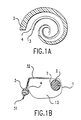
- Figs. 1a and 1b illustrate the position of the electrode array in respectively planar and cross sectional views of the cochlea immediately after insertion.
- Figs. 2a and 2b illustrate the position of the electrode array in respectively planar and cross sectional views of the cochlea after retro positioning.
- Figs. 3a and 3b illustrate a perimodiolar electrode array with respectively a short and a long microgroove.
- Fig. 4 is a cross section view of an electrode array with a wire in a circular microgroove which is tangent to the outer surface of the carrier.
- Fig. 5 is a cross section view of an electrode array with a ribbon in a u-shaped microgroove with a single electrode contact diametrically opposed to the microgroove.
- Fig. 6 is a longitudinal view of an electrode array showing the microgroove, tunnel, apical and basal silicon micro notches, and a wire-like element in the microgroove.
- Figs. 7a and 7b are respective views of the basal portion of an electrode array before and after the retro positioning technique.
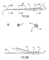
- Figs. 8a and 8b respectively illustrate a partitioned electrode array before insertion and with the perimodiolar segment lifted.
- Figs. 9a and 9b are cross section views of partitioned electrode arrays having two different methods of attachment and alignment of the branches.
- Fig. 10 illustrates an electrode array which is not part of the present invention with an external rod for retro positioning.
- A preferred embodiment of the present direction is directed to a straight multi-electrode cochlear prosthesis with an outer (or basal) end and an inner (or apical) end which is designed to be inserted into the upright, conical and spiraling shape of the cochlea. During surgical insertion, the electrode array conforms to the outer wall of the fluid filled scala tympani. The scala tympani is the natural canal into which a cochlear prosthesis is inserted by a surgeon.
- A preferred embodiment provides an electrode array designed to displace the whole electrode array, or any portion of it, away from the outer wall of the scala tympani and toward the inner wall. Any undisplaced portion of the electrode array remains against the outer wall. The active displacement of the electrode is performed by a surgeon through a retro-positioning technique. With the retro-positioning technique, the electrode is drawn back after full or partial insertion, except at the apical end where the electrode is held in place within the electrode carrier with a flexible element. Such an element is designed to be flexible enough for ease of insertion yet rigid enough to hold the apical tip of the electrode array stationary throughout the retracting process.
- The cochlear prostheses, in a preferred embodiment, is fabricated with an inner tunnel molded near or on the edges of the electrode carrier. The tunnel is cylindrical, rectangular or u-shaped. A slit exposes the inner tunnel to the outer surface of the carrier. The slit tunnel thus forms a micro-groove. A wire, rod or ribbon is placed inside the microgroove as the flexible element. The apical end of the flexible element is fixed in a molded silicone notch at the apical end of the carrier. The basal end of the flexible element may slide through a short silicone tunnel molded inside the microgroove.
- After insertion of the electrode carrier into the cochlea, the flexible element is held stationary posterior to the cochleostomy by the surgeon. The electrode carrier is then gently retracted. This slight pulling of the electrode carrier out of the cochlea dislocates the inner flexible element from the carrier's microgroove, except at the apex where the flexible element fits into a silicone hollow cavity. The surgeon's continued retracting motion on the electrode carrier causes the array to wrap around the inner wall of the cochlea.
- In an alternative embodiment, the electrode carrier is partitioned into two branches. The two confluent branches are initially held together, and after insertion, the confluent branches are separated. In this final state, one branch rests against the outer wall of the scala tympani while the other branch lies against the inner wall.
- Figs. 1 and 2 illustrate a cochlea with an
inner wall 4, an outer wall 1, and a spiral ganglion cells population 3. Fig. 1a shows atapered electrode carrier 2 positioned against the outer wall 1, while Fig. 2a shows thecarrier 2 positioned against theinner wall 4. Figs. 1b and 2b show a cross sectional view of the scala tympani region of acochlea 13 and the position ofelectrode carrier 2 before and after retro-positioning of the carrier. As can be observed between 1a and 2a, the length ofelectrode carrier 2 when it lays against the outer wall 1 is longer than when it lays against theinner wall 4. - A preferred embodiment provides a reliable way of moving
electrode carrier 2 from the outer wall 1 to theinner wall 4 of the scala tympanispiral 13. This is done after insertion of theelectrode carrier 2 by retracting the electrode carrier from the cochlea toward the base, 20 in Fig. 3, while maintaining in place the electrode carrier apex portion of thecarrier 21, where it is fixed by a flexible, yet firm,element 5. Both theelectrode carrier 2 and theflexible element 5 have anapical end 21 and abasal end 20. Theflexible element 5 may be shorter thanelectrode carrier 2, as shown in Fig. 3a, or extend to theapical end 21 of theelectrode carrier 2, as shown in Fig. 3b. In both cases, theflexible element 5 is lodged into amicrogroove 8, shown in Figs. 4 and 5. - Fig. 4 shows the
electrode carrier 2 with amicrogroove 8. The microgroove is designed to receive theflexible element 5. The cross section of themicrogroove 8 may be circular, as shown on Fig. 4, u-shaped, as shown on Fig. 5, or elliptical, rectangular, square, or any other shape which may be profitable. The cross sectional area ofmicrogroove 8 may encompass up to 50% of that of theelectrode carrier 2. The position of themicrogroove 8 on theelectrode carrier 2 may be flush or slightly recessed with respect to the outer surface of theelectrode carrier 2. The combination of flush and recessed length affects the amount of force necessary during retro-positioning to dislodge theflexible element 5 embedded in themicrogroove 8. It is desirable that themicrogroove 8 be designed so that the embeddedflexible element 5 dislodges easily out of theelectrode carrier 2, while having enough constriction to maintain theflexible element 5 inside themicrogroove 8 during insertion. The advantage of having amicrogroove 8 incarrier 2 is that the overall electrode carrier presents a uniform and smooth surface to the tissue of the inner ear. Such a smooth surface has lower friction and facilitates insertion. Trauma is minimized and yet it is feasible to add elements into the groove to perform various desirable functions. - The negatively casted
microgroove 8 is designed to receive aflexible element 5, a wire or a ribbon, for example. Theflexible element 5 which is positioned in themicrogroove 8 is preferably a 80 or 100 mm diameter super flexible nitinol wire with rounded edges, pieces of which may be produced by Nitinol Devices and Components Inc., Fremont, CA., or EuroFlex, Pforzheim, Germany. The finished metal is preferably smoothed by electro polishing. Theflexible element 5 can also be made in the form of a nitinol ribbon with rounded edges as shown on Fig. 5. In this case themicrogroove 8 would likely be of rectangular or U shape in cross section. Theflexible element 5 may also be a polymer rod, resistant to the heat necessary to fast cure the injection moldedelectrode carrier 2. Theflexible element 5 can also be tapered in shape. In another embodiment, theflexible element 5 which is fitted in themicrogroove 8 may be pre coated to impart biostability, biocompatibility, dielectric properties, hydrophobicity, and surface friction reduction properties. The surface coating may be done by Advance Surface technology Inc., Billerica MA, or Specialty Coating Systems, Indianapolis. After theflexible element 5 and theelectrode carrier 2 are fabricated, then theflexible element 5 is inserted into thetunnel 6, threaded through themicrogroove 8, and lodged into the apical micro notch 11. In this manner the assembly of the 2 parts (flexible element 5 and electrode carrier 2) is most simple and economical. - The length of the
microgroove 8 andflexible element 5 may be equal or shorter than the span of the insertedelectrode carrier 2, as shown in Figs. 3a and. 3b. In the first case,apical section 22 is designed to lay against the outer wall andinner section 23 is designed to hug theinner wall 4 of the scala tympani 13. The advantage of ashorter microgroove 8 is that a full insertion of theelectrode carrier 2 is facilitated. Theapical section 22 of theelectrode carrier 2 has no flexible element added tomicrogroove 8. In this case, four electrode contacts 7 may be variously distributed onapical section 22 of theelectrode carrier 2. The remaining contacts 7, eight of them in Fig. 3a, may be closely or as widely spaced oninner section 23 ofelectrode carrier 2. The advantage of such a design is that it is possible for example, to stimulate 80% of the spiral ganglion cells 3 in Rosenthal's canal located near the basal turn of the cochlea, and also the residual proximal process, if any, which innervate the apex of the inner ear. - In an embodiment where the length of the
microgroove 8 andflexible element 5 extend to the tip ofelectrode carrier 2, as shown in Fig. 3b, the insertion of the electrode carrier need not exceed 23 millimeters for theelectrode carrier 2 to completely surround the Rosenthal's canal, following retro-positioning. Therewith, the electrode contacts 7 may be densely packed in the apical 12 to 1 5 millimeters ofelectrode carrier 2. It is calculated that up to 10 millimeters ofelectrode carrier 2 could be retracted after insertion. Retraction length however, depends on specific insertion depth and cochlea dimensions. - The preferred method, which is not part of the present invention, of forming the
microgroove 8 is by negative casting. The negative casting operation may be realized with an existing mold of uniform profile in which a nitinol wire of desired shape and diameter may be attached to one edge of the cast. The wire may be fastened to the mold with silicone. Following injection molding, the nitinol wire is easily removed by pulling it out of the moldedcarrier 2, effectively leaving amicrogroove 8. If significantly recessed, the wire can be removed after cutting a slit with a micro scalpel above or near the location of the wire. Thelips 41 of themicrogroove 8 may be enlarged with micro-scissors. Monolithic molds may also be designed to include the formation of themicrogroove 8. - Referring to Fig. 6, the most
apical end 21 of themicrogroove 8 is terminated in the form of a micro notch 11 a few millimeters long. The micro notch 11 is designed to loosely or tightly hold the apical end of theflexible element 5. At thebasal end 20 of theelectrode carrier 2, just posterior to the full insertion length of the electrode carrier (typically 30 millimeters or less), a short silicone bridge a few millimeters long covers themicrogroove 8 forming atunnel 6 through which the flexible member passes.Microgroove 8 extends past thebridge 6 inbasal direction 20, for some distance. - At points posterior to the
short tunnel 6, are locatedseveral notches 10 which are, for example, 5 millimeters apart. Thenotches 10 may be 2 millimeters deep by way of illustration. Thenotches 10 are designed to receive thebasal end 20 of theflexible element 5 located into themicrogroove 8, and to provide a locking mechanism for theflexible element 5, following retro-positioning of theelectrode carrier 2. The cross sectional shape and inner dimensions of thenotches 10 are therefore made similar to that of theflexible element 5.Such notches 10 as described here are easily and economically built by covering small separate segments offlexible element 5 with silicone. The subsequent curing process causes excellent bonding between the silicone ofnotch 10 and that of carrier 2 (silicone to silicone bonding). Removal of the small separate segments offlexible element 5 leavesperfect notches 10. The cross sectional dimensions ofnotch 10 can also be made larger than those offlexible element 5 to facilitate the introduction of the mostbasal end 20 of theflexible element 5 into thenotch 10. - Referring now to Figure 7a, after the full or partial insertion of the
electrode array 2 into the scala tympani, the surgeon hold theflexible element 5 with some tools such as micro forceps atlocation 12 ofapical end 21. The surgeon then retract theelectrode carrier 2, held atlocation 13, for example, with the other hand. Theelectrode carrier 2 retracts easily until it is wrapped around innerscala tympani wall 4. At this point, the surgeon inserts thebasal end 20 offlexible element 5 into one of thenotches 10, as depicted in Fig. 7b. A cross sectional view of the final position ofelectrode carrier 2 andflexible element 5 is shown in Fig. 2b. - Another embodiment of the present invention is directed to a partitioned perimodiolar electrode carrier. Such an electrode carrier is shown in Fig. 8. Fig. 8a illustrates a cross section of the electrode carrier at three representative locations. The intra-cochlear electrode carrier is segmented into a
perimodiolar section 81 and an outerwall facing branch 82. The portion of the electrode carrier situated posterior to the entrance of the cochlea is in the form of amonolithic silicone matrix 83. Thus,perimodiolar section 81 and outerwall facing branch 82 are silicone bonded together to formmonolithic silicone matrix 83. - In a preferred embodiment, the
segments perimodiolar segment 81 is shorter than the outerwall facing segment 82 to accommodate the real length difference between the inner and outer wall 1 and 3 of the scala tympani 13. Initially, and during insertion of the carrier, the twosegments pre-molded microgroove 92 into which fits a pre-moldedmicro protuberance 91 as show in Figs. 9a and 9b. It is understood that the pre-molded parts may be of any shape, form, length, and situated at any location onsegments - Shortly after full insertion of the whole carrier, the
perimodiolar section 81 is separated from the outerwall facing segment 82. Theperimodiolar section 81 is then launched toward theinner wall 4 of the scala tympani 13 with the help offlexible element 5 which is located between the twosegments microgroove 8.Microgroove 8 may be divided betweensegments microgroove 8 may also be used as deemed profitable to the design. - The
flexible element 5 lodged between the twosegments perimodiolar section 81 and compel theperimodiolar section 81 to conform to theinner contour 4 of the scala tympani. The preferred method for actively displacing theperimodiolar segment 81 is by retro-positioning of the electrode carrier as described previously. An alternative embodiment method for actively displacing theperimodiolar segment 81 is by exerting a forward force on theflexible element 5 in microgroove. The force exerted in the direction of the long axis of the electrode carrier dislodgesflexible element 5 from themicrogroove 8. At the same time theperimodiolar segment 81 is moved in a forward and radial direction toward theinner wall 4 of the scala tympani 13. Themicrogroove 8 may be constructed as described previously, and it may be located on either one or bothbranches apical part 21 of the outerwall facing branch 82, and eight contacts each 1.1 millimeters apart are distributed on the apical section of theperimodiolar branch 81. - The advantage of such a segmented electrode design is that one branch of the electrode carrier is fully, or maximally inserted, while another branch surrounds the inner scala tympani wall. With electrode contacts variously distributed on the two segments of the electrode carrier, it is feasible to stimulate both spiral ganglion cells, 80% of which are located near the cochlear basal turn, and existing residual neural tissue in the upper turns of the cochlea.
- In yet another embodiment which is not part of the invention the electrode carrier is again a segmented two branch design as shown in Figs. 8a and 8b. The
perimodiolar branch 81, however, is pre-shaped to the form of theinner wall 4 of the scala tympani 13. The memory shaped form of theperimodiolar branch 81 is held straight by mean of a nitinol rodflexible element 5 which fits between thepre-shaped perimodiolar branch 81 and the outerwall facing branch 82. At the apical end of the carrier, a notch, 11 as in Fig. 6, receives the apical end of the nitinol rodflexible element 5. Theflexible element 5 slides freely in the micro notch 11. After full insertion of the electrode carrier composed ofperimodiolar section 81 and outerwall facing section 82 in thescala tympani 13, the nitinol rodflexible element 5 is pulled back slightly out of the notch 11. The releasedperimodiolar branch 81 then assumes its pre-shaped form. - In yet another embodiment which is not part of the present invention, the
flexible element 5 is placed outside and parallel to theelectrode carrier 2 instead of in a microgroove. This is shown in Fig. 10. While the electrode carrier has no moldedmicrogroove 8, the electrode carrier again has a micro notch at the apex 21 (not shown), atunnel 6 at thebasal end 20, and several basal notches (not shown) posterior to thebasal end 20. Theflexible element 5 is again made of a super-flexible nitinol wire, and is threaded through thebasal tunnel 6 and into the apical micro notch not shown. Insertion of theelectrode carrier 2 with theflexible element 5 is done by alternatingly pushing theelectrode carrier 2 and theflexible element 5 into the scala tympani 13. After full or partial insertion thecarrier 2 is retro-positioned as it has been described earlier.
Claims (22)
- An implantable cochlear electrode array comprising:an electrode array carrier (2) having an outer end (20) and an inner end (21), to electrically stimulate a scala tympani wall in which the carrier is implanted; and a flexible element (5) attached to the electrode carrier (2) towards inner end (20); characterised bya groove (8) within the electrode carrier (2) extending from the outer end (20) of the electrode carrier at least part way towards the inner end (21) wherein at least a portion of the groove (8) penetrates the surface of the electrode carrier (2); andwherein the carrier (2) and the flexible element (5), which is located in the groove, are arranged with respect to each other so that the flexible element (5) is maintainable within the groove (8) until after the electrode array is fully inserted in a cochlea, when movement of the carrier (2) with respect to the flexible element (5) towards the outer end (20) causes the electrode carrier (2) to wrap around an inner scala tympani wall.
- An implantable cochlear electrode array according to claim 1, wherein the electrode carrier (2) further comprises:a perimodiolar section (81) to be positioned next to an inner scala tympani wall of the cochlea, andan outer wall section (82) to be positioned next to an outer scala tympani wall of the cochlea; andwherein the electrode carrier (2) and the flexible element (5) are arranged with respect to each other so that, after the electrode array is inserted in a cochlea, movement of the carrier with respect to the flexible element (5) towards the outer end (20) causes the perimodiolar section (81) of the electrode carrier to warp around an inner scala tympani wall.
- A cochlear electrode array as in claim 1 or 2, wherein the groove (8) has a fixed cross-sectional shape.
- A cochlear electrode array as in claim 3, wherein the cross-sectional shape of the groove (8) is circular.
- A cochlear electrode array as in claim 3, wherein the cross-sectional shape of the groove (8) is rectangular.
- A cochlear electrode array as in claim 3, wherein the cross-sectional shape of the groove (8) is u-shaped.
- A cochlear electrode array as in claim 1 or 2, wherein the groove (8) has a variable cross-sectional shape.
- A cochlear electrode array as in claim 1, wherein the groove (8) is substantially parallel to a long axis of the electrode carrier (2).
- A cochlear electrode array as in claim 1 or 2, wherein the groove (8) significantly deviates from a long axis of the electrode carrier (2).
- A cochlear electrode array as in claim 1 or 2, wherein the groove (8) has an inner notch (11) located near the inner end (21) to maintain the inner end of the flexible element (5) and an adjacent portion of the electrode carrier (2) together.
- A cochlear electrode array as in claim 1 or 2, wherein the flexible element (5) is a wire made of biocompatible material.
- A cochlear electrode array as in claim 11, wherein the wire (5) is made of nitinol.
- A cochlear electrode array as in claim 11, wherein the wire (5) has a surface coating to modify its surface characteristics.
- A cochlear electrode array as in claim 11, wherein the wire (5) has a surface coating to modify its dielectric characteristics.
- A cochlear electrode array as in claim 1 or 2, wherein the flexible element (5) is a flexible polymeric rod.
- A cochlear electrode array as in claim 1 or 2, wherein a portion of the inner end (21) of the electrode carrier (2) extends beyond the inner ends of the groove (8) and the flexible element (5) so that the inner end (21) of the electrode carrier (2) does not wrap around the inner scala tympani wall when the electrode carrier (2) is partially withdrawn after insertion in the cochlea.
- A cochlear electrode array as in claim 1 or 2, further including:a bridge portion of the electrode carrier (2) located near the outer end (20) of the electrode carrier which closes over the surface penetration of the groove to form a closed tunnel around the flexible element and to prevent the flexible element from lifting out of the groove (8) at the bridge.
- A cochlear electrode array as in claim 1 or 2, further including:at least one notch (10) near the outer end (20) of the electrode carrier (2) to securely hold the outer end of the flexible member (5) after the electrode array has been implanted in the cochlea.
- A cochlear electrode array as in claim 1 or 2, wherein the electrode carrier (2) and the flexible element (5) are further arranged with respect to each other so that after the electrode array is inserted in a cochlea, movement of the carrier with respect to the flexible element towards the outer end (20) pulls the electrode carrier away from the flexible element, which emerges from the groove (8) through the surface of the electrode carrier, except where the electrode carrier and the flexible element are attached, so that the electrode carrier wraps around an inner scala tympani wall.
- A cochlear electrode array as in claim 2, wherein the groove (8) is within the perimodiolar section (81) of the electrode carrier.
- A cochlear electrode array as in claim 2, wherein the groove (8) is within the outer wall section of the electrode carrier.
- A cochlear electrode array as in claim 2, wherein the perimodiolar section (81) is shorter than the outer wall section to accommodate the real length difference between the inner and outer walls of the scala tympani of a cochlea.
Applications Claiming Priority (5)
| Application Number | Priority Date | Filing Date | Title |
|---|---|---|---|
| US4049997P | 1997-03-10 | 1997-03-10 | |
| US40499P | 1997-03-10 | ||
| US7137598P | 1998-01-15 | 1998-01-15 | |
| US71375P | 1998-01-15 | ||
| PCT/IB1998/000507 WO1998040119A1 (en) | 1997-03-10 | 1998-03-10 | Apparatus and method for perimodiolar cochlear implant with retro-positioning |
Publications (2)
| Publication Number | Publication Date |
|---|---|
| EP0966310A1 EP0966310A1 (en) | 1999-12-29 |
| EP0966310B1 true EP0966310B1 (en) | 2006-02-08 |
Family
ID=26717114
Family Applications (1)
| Application Number | Title | Priority Date | Filing Date |
|---|---|---|---|
| EP98909707A Expired - Lifetime EP0966310B1 (en) | 1997-03-10 | 1998-03-10 | Apparatus and method for perimodiolar cochlear implant with retro-positioning |
Country Status (8)
| Country | Link |
|---|---|
| US (1) | US5999859A (en) |
| EP (1) | EP0966310B1 (en) |
| JP (1) | JP4018156B2 (en) |
| AT (1) | ATE317278T1 (en) |
| AU (1) | AU746636B2 (en) |
| CA (1) | CA2283112C (en) |
| DE (1) | DE69833426T2 (en) |
| WO (1) | WO1998040119A1 (en) |
Cited By (1)
| Publication number | Priority date | Publication date | Assignee | Title |
|---|---|---|---|---|
| US9295831B2 (en) | 2014-02-11 | 2016-03-29 | Med-El Elektromedizinische Geraete Gmbh | Electrode with anti-spring back component |
Families Citing this family (58)
| Publication number | Priority date | Publication date | Assignee | Title |
|---|---|---|---|---|
| US6125302A (en) | 1997-09-02 | 2000-09-26 | Advanced Bionics Corporation | Precurved modiolar-hugging cochlear electrode |
| US6321125B1 (en) * | 1998-08-26 | 2001-11-20 | Advanced Bionics Corporation | Cochlear electrode system including distally attached flexible positioner |
| US6397110B1 (en) * | 1998-08-26 | 2002-05-28 | Advanced Bionics Corporation | Cochlear electrode system including detachable flexible positioner |
| US6968238B1 (en) | 1998-08-26 | 2005-11-22 | Kuzma Janusz A | Method for inserting cochlear electrode and insertion tool for use therewith |
| AU776958B2 (en) * | 1999-05-21 | 2004-09-30 | Cochlear Limited | A cochlear implant electrode array |
| US6487453B1 (en) | 1999-08-09 | 2002-11-26 | Advanced Bionics Corporation | Electrode system for ossified cochlea |
| US6498954B1 (en) * | 2000-01-14 | 2002-12-24 | Advanced Bionics Corporation | Apex to base cochlear implant electrode |
| ATE518500T1 (en) * | 2000-11-29 | 2011-08-15 | Cochlear Ltd | PRE-FORMED IMPLANT WITH A SERIES OF ELECTRODES FOR USE IN THE CURB |
| EP1370205B1 (en) * | 2001-03-19 | 2013-08-14 | Cochlear Limited | Insertion tool system for an electrode array |
| AUPR408001A0 (en) * | 2001-03-29 | 2001-04-26 | Cochlear Limited | Laminated electrode for a cochlear implant |
| WO2003024153A1 (en) * | 2001-09-13 | 2003-03-20 | Med-El Elektromedizinische Geräte Ges.m.b.H. | Intra-cochlear electrode with a partially detachable hydrophilic segment for deferred self-positioning |
| AU2002363103B2 (en) | 2001-10-24 | 2008-10-16 | Med-El Elektromedizinische Gerate Ges.M.B.H. | Implantable fluid delivery apparatuses and implantable electrode |
| US20070088335A1 (en) * | 2001-10-24 | 2007-04-19 | Med-El Elektromedizinische Geraete Gmbh | Implantable neuro-stimulation electrode with fluid reservoir |
| ATE531349T1 (en) | 2002-02-22 | 2011-11-15 | Cochlear Ltd | INTRODUCTION DEVICE FOR AN ELECTRODE ARRANGEMENT |
| WO2004050166A1 (en) * | 2002-12-02 | 2004-06-17 | Med-El Elektromedizinsche Geraete Gmbh | Fluid switch controlled trans-cutaneously via a magnetic force |
| US8036753B2 (en) * | 2004-01-09 | 2011-10-11 | Cochlear Limited | Stimulation mode for cochlear implant speech coding |
| WO2006040690A2 (en) * | 2004-03-15 | 2006-04-20 | Med-El Elektromedizinische Geraete Gmbh | Cochlear implant electrode with adjustable subdivision for middle ear functions |
| US8311649B2 (en) * | 2004-05-26 | 2012-11-13 | Advanced Bionics | Cochlear lead |
| US7778434B2 (en) * | 2004-05-28 | 2010-08-17 | General Hearing Instrument, Inc. | Self forming in-the-ear hearing aid with conical stent |
| US20060098833A1 (en) * | 2004-05-28 | 2006-05-11 | Juneau Roger P | Self forming in-the-ear hearing aid |
| US8805546B2 (en) * | 2004-09-07 | 2014-08-12 | Hearworks Pty, Ltd | Cochlear electrode with precurved and straight sections |
| US20060212094A1 (en) * | 2004-12-31 | 2006-09-21 | Ludwig Moser | Middle ear multi-channel electrode |
| US8369958B2 (en) * | 2005-05-19 | 2013-02-05 | Cochlear Limited | Independent and concurrent processing multiple audio input signals in a prosthetic hearing implant |
| US8831739B2 (en) * | 2005-06-02 | 2014-09-09 | Huntington Medical Research Institutes | Microelectrode array for chronic deep-brain microstimulation for recording |
| US20100331913A1 (en) * | 2005-10-28 | 2010-12-30 | Mann Alfred E | Hybrid multi-function electrode array |
| AR059786A1 (en) * | 2006-03-09 | 2008-04-30 | Med El Elektromed Geraete Gmbh | CONFIGURATION OF COCLEAR IMPLANT ELECTRODE TO ELECT PHARMACOS |
| US8046081B2 (en) * | 2006-05-18 | 2011-10-25 | Med-El Elektromedizinische Geraete Gmbh | Implanted system with DC free inputs and outputs |
| US8000797B1 (en) * | 2006-06-07 | 2011-08-16 | Advanced Bionics, Llc | Systems and methods for providing neural stimulation with an asynchronous stochastic strategy |
| KR100735078B1 (en) * | 2006-07-21 | 2007-07-03 | (주)머티리얼솔루션테크놀로지 | Cochlear implant |
| US8731673B2 (en) | 2007-02-26 | 2014-05-20 | Sapiens Steering Brain Stimulation B.V. | Neural interface system |
| US8019430B2 (en) * | 2007-03-21 | 2011-09-13 | Cochlear Limited | Stimulating auditory nerve fibers to provide pitch representation |
| WO2009111334A2 (en) * | 2008-02-29 | 2009-09-11 | Otologics, Llc | Improved bi-modal cochlea stimulation |
| US9474546B1 (en) | 2008-04-18 | 2016-10-25 | Advanced Bionics Ag | Pre-curved electrode array insertion tools |
| EP2113283B1 (en) | 2008-04-30 | 2012-10-10 | Medizinische Hochschule Hannover | System for insertion of an implant |
| US8010210B2 (en) * | 2008-04-30 | 2011-08-30 | Medizinische Hochschule Hannover | Apparatus and system for insertion of an implant |
| US20090287277A1 (en) * | 2008-05-19 | 2009-11-19 | Otologics, Llc | Implantable neurostimulation electrode interface |
| WO2010015016A1 (en) * | 2008-08-08 | 2010-02-11 | Cochlear Limited | Electrode for a cochlear implant |
| EP2349464B1 (en) | 2008-09-16 | 2013-10-30 | Med-El Elektromedizinische Geräte GmbH | Double branch cochlear implant electrode for penetration into the nerve tissue within the modiolus |
| CN102186528B (en) * | 2008-10-15 | 2013-08-07 | Med-El电气医疗器械有限公司 | Inner ear drug delivery device |
| US20100121256A1 (en) * | 2008-11-10 | 2010-05-13 | Med-El Elektromedizinische Geraete Gmbh | Implantable and Refillable Drug Delivery Reservoir |
| US9044588B2 (en) | 2009-04-16 | 2015-06-02 | Cochlear Limited | Reference electrode apparatus and method for neurostimulation implants |
| US8880193B1 (en) | 2009-05-22 | 2014-11-04 | Advanced Bionics, Llc | Cochlear electrode array |
| WO2010138911A1 (en) | 2009-05-29 | 2010-12-02 | Otologics, Llc | Implantable auditory stimulation system and method with offset implanted microphones |
| WO2011005993A1 (en) | 2009-07-08 | 2011-01-13 | Advanced Bionics, Llc | Lead insertion tools |
| US8712554B2 (en) * | 2009-07-21 | 2014-04-29 | Advanced Bionics | Integrated wire carrier for electrode array |
| US9033869B2 (en) | 2010-05-27 | 2015-05-19 | Advanced Bionics, Llc | Cochlear lead |
| US9037267B2 (en) | 2010-05-27 | 2015-05-19 | Advanced Bionics Llc | Cochlear lead |
| US8774944B2 (en) | 2010-06-25 | 2014-07-08 | Advanced Bionics Ag | Tools, systems, and methods for inserting an electrode array portion of a lead into a bodily orifice |
| US8473075B2 (en) | 2010-06-25 | 2013-06-25 | Advanced Bionics | Cochlear implant system with removable stylet |
| US8753353B2 (en) | 2010-06-25 | 2014-06-17 | Advanced Bionics Ag | Tools, systems, and methods for inserting an electrode array portion of a lead into a bodily orifice |
| US8753352B2 (en) | 2010-06-25 | 2014-06-17 | Advanced Bionics Ag | Tools, systems, and methods for inserting a pre-curved electrode array portion of a lead into a bodily orifice |
| DE102012014714B4 (en) * | 2012-03-02 | 2019-09-05 | Cerbomed Gmbh | Electrode assembly and system consisting of an electrode assembly and a number of electrodes |
| JP6029056B2 (en) | 2012-08-31 | 2016-11-24 | 国立大学法人大阪大学 | Artificial sensory epithelium |
| US9333338B2 (en) * | 2013-10-15 | 2016-05-10 | Med-El Elektromedizinische Geraete Gmbh | Electrode for common cavity cochlear malformation |
| US11071869B2 (en) | 2016-02-24 | 2021-07-27 | Cochlear Limited | Implantable device having removable portion |
| CN109562259B (en) * | 2016-08-11 | 2023-06-27 | 领先仿生公司 | Cochlear implant comprising electrode array and method for manufacturing electrode array |
| US11433246B2 (en) | 2017-11-30 | 2022-09-06 | Advanced Bionics Ag | Slotted stiffening member for facilitating an insertion of an electrode lead into a cochlea of a patient |
| CN111372647B (en) * | 2018-04-13 | 2021-11-16 | 领先仿生公司 | Pull wire shifting assembly and method |
Family Cites Families (11)
| Publication number | Priority date | Publication date | Assignee | Title |
|---|---|---|---|---|
| DK141034B (en) * | 1977-11-22 | 1979-12-31 | C C Hansen | ELECTRODE FOR INSERTING IN THE SNAIL OF THE CITY (COCHLEA) |
| CH657984A5 (en) * | 1979-09-24 | 1986-10-15 | Ingeborg Johanna Hochmair Deso | ARRANGEMENT FOR ELECTRICALLY STIMULATING A RECEPTOR, RECEIVER UNIT FOR THE ARRANGEMENT, TRANSMITTER UNIT FOR THE ARRANGEMENT AND METHOD FOR THE PRODUCTION THEREOF. |
| US4898183A (en) * | 1987-07-24 | 1990-02-06 | Cochlear Pty. Limited | Apparatus and method for insertion of cochlear electrode assembly |
| US5630839A (en) * | 1991-10-22 | 1997-05-20 | Pi Medical Corporation | Multi-electrode cochlear implant and method of manufacturing the same |
| DE4200030C2 (en) * | 1992-01-02 | 1996-09-12 | Eckhard Prof Dr Alt | catheter |
| WO1994000088A1 (en) * | 1992-06-22 | 1994-01-06 | The University Of Melbourne | Curved electrode array |
| US5431696A (en) * | 1992-10-13 | 1995-07-11 | Atlee, Iii; John L. | Esophageal probe for transeophageal cardiac stimulation |
| DE69625805T2 (en) * | 1995-03-30 | 2003-11-13 | Cochlear Ltd | ELECTRODE ARRANGEMENTS FOR COCHLEAR IMPLANT AND POSITIONING SYSTEM |
| US5545219A (en) * | 1995-03-30 | 1996-08-13 | Cochlear, Ltd. | Cochlear electrode implant assemblies with positioning system therefor |
| US5645585A (en) * | 1996-03-15 | 1997-07-08 | Cochlear Ltd. | Cochlear electrode implant assembly with positioning system therefor |
| AU702746B2 (en) * | 1995-09-20 | 1999-03-04 | Cochlear Limited | Bioresorbable polymer use in cochlear and other implants |
-
1998
- 1998-03-10 AT AT98909707T patent/ATE317278T1/en active
- 1998-03-10 EP EP98909707A patent/EP0966310B1/en not_active Expired - Lifetime
- 1998-03-10 CA CA002283112A patent/CA2283112C/en not_active Expired - Fee Related
- 1998-03-10 US US09/037,893 patent/US5999859A/en not_active Expired - Lifetime
- 1998-03-10 JP JP53938898A patent/JP4018156B2/en not_active Expired - Lifetime
- 1998-03-10 AU AU64165/98A patent/AU746636B2/en not_active Expired
- 1998-03-10 DE DE69833426T patent/DE69833426T2/en not_active Expired - Fee Related
- 1998-03-10 WO PCT/IB1998/000507 patent/WO1998040119A1/en active IP Right Grant
Cited By (1)
| Publication number | Priority date | Publication date | Assignee | Title |
|---|---|---|---|---|
| US9295831B2 (en) | 2014-02-11 | 2016-03-29 | Med-El Elektromedizinische Geraete Gmbh | Electrode with anti-spring back component |
Also Published As
| Publication number | Publication date |
|---|---|
| CA2283112C (en) | 2005-11-08 |
| WO1998040119A1 (en) | 1998-09-17 |
| JP4018156B2 (en) | 2007-12-05 |
| EP0966310A1 (en) | 1999-12-29 |
| ATE317278T1 (en) | 2006-02-15 |
| AU746636B2 (en) | 2002-05-02 |
| DE69833426D1 (en) | 2006-04-20 |
| DE69833426T2 (en) | 2006-08-17 |
| AU6416598A (en) | 1998-09-29 |
| JP2001514553A (en) | 2001-09-11 |
| CA2283112A1 (en) | 1998-09-17 |
| US5999859A (en) | 1999-12-07 |
Similar Documents
| Publication | Publication Date | Title |
|---|---|---|
| EP0966310B1 (en) | Apparatus and method for perimodiolar cochlear implant with retro-positioning | |
| EP2588184B1 (en) | Ear implant electrode and method of manufacture | |
| AU761806B2 (en) | Modiolar hugging electrode array | |
| US7966077B2 (en) | Electrode assembly for a stimulating medical device | |
| US10016589B2 (en) | Mid-scalar electrode array | |
| US7328072B2 (en) | Telescopic array for a cochlear implant | |
| CN105658185B (en) | Electrode contacts with hydrogel covering | |
| US20130238074A1 (en) | Ear Implant Electrode and Method of Manufacture | |
| EP3057651B1 (en) | Electrode for common cavity cochlear malformation | |
| WO2008031144A1 (en) | Implantable electrode array | |
| US10722702B2 (en) | Transmodiolar electrode array and a manufacturing method | |
| US9446230B1 (en) | Cochlear implant electrode array and method for inserting the same into a human cochlea | |
| AU2004200645A1 (en) | Telescopic array for a cochlear implant |
Legal Events
| Date | Code | Title | Description |
|---|---|---|---|
| PUAI | Public reference made under article 153(3) epc to a published international application that has entered the european phase |
Free format text: ORIGINAL CODE: 0009012 |
|
| 17P | Request for examination filed |
Effective date: 19990826 |
|
| AK | Designated contracting states |
Kind code of ref document: A1 Designated state(s): AT BE DE FR GB IT NL |
|
| 17Q | First examination report despatched |
Effective date: 20030602 |
|
| RIC1 | Information provided on ipc code assigned before grant |
Ipc: 7A 61N 1/05 B Ipc: 7A 61N 1/36 A |
|
| GRAP | Despatch of communication of intention to grant a patent |
Free format text: ORIGINAL CODE: EPIDOSNIGR1 |
|
| GRAS | Grant fee paid |
Free format text: ORIGINAL CODE: EPIDOSNIGR3 |
|
| GRAA | (expected) grant |
Free format text: ORIGINAL CODE: 0009210 |
|
| AK | Designated contracting states |
Kind code of ref document: B1 Designated state(s): AT BE DE FR GB IT NL |
|
| REG | Reference to a national code |
Ref country code: GB Ref legal event code: FG4D |
|
| REG | Reference to a national code |
Ref country code: GB Ref legal event code: ERR Free format text: NOTIFICATION HAS NOW BEEN RECEIVED FROM THE EUROPEAN PATENT OFFICE THAT THE CORRECT NAME IS: MED-EL ELEKTROMEDIZINISCHE GERATE GMBH THIS CORRECTION WILL NOT BE PUBLISHED IN THE EUROPEAN PATENT BULLETIN |
|
| REF | Corresponds to: |
Ref document number: 69833426 Country of ref document: DE Date of ref document: 20060420 Kind code of ref document: P |
|
| ET | Fr: translation filed | ||
| PLBE | No opposition filed within time limit |
Free format text: ORIGINAL CODE: 0009261 |
|
| STAA | Information on the status of an ep patent application or granted ep patent |
Free format text: STATUS: NO OPPOSITION FILED WITHIN TIME LIMIT |
|
| 26N | No opposition filed |
Effective date: 20061109 |
|
| PGFP | Annual fee paid to national office [announced via postgrant information from national office to epo] |
Ref country code: NL Payment date: 20080324 Year of fee payment: 11 Ref country code: GB Payment date: 20080327 Year of fee payment: 11 |
|
| PGFP | Annual fee paid to national office [announced via postgrant information from national office to epo] |
Ref country code: DE Payment date: 20080430 Year of fee payment: 11 |
|
| PGFP | Annual fee paid to national office [announced via postgrant information from national office to epo] |
Ref country code: IT Payment date: 20080328 Year of fee payment: 11 Ref country code: BE Payment date: 20080410 Year of fee payment: 11 |
|
| BERE | Be: lapsed |
Owner name: *MED-EL ELEKTROMEDIZINISCHE GERATE G.M.B.H. Effective date: 20090331 |
|
| GBPC | Gb: european patent ceased through non-payment of renewal fee |
Effective date: 20090310 |
|
| NLV4 | Nl: lapsed or anulled due to non-payment of the annual fee |
Effective date: 20091001 |
|
| PG25 | Lapsed in a contracting state [announced via postgrant information from national office to epo] |
Ref country code: DE Free format text: LAPSE BECAUSE OF NON-PAYMENT OF DUE FEES Effective date: 20091001 |
|
| PG25 | Lapsed in a contracting state [announced via postgrant information from national office to epo] |
Ref country code: NL Free format text: LAPSE BECAUSE OF NON-PAYMENT OF DUE FEES Effective date: 20091001 Ref country code: BE Free format text: LAPSE BECAUSE OF NON-PAYMENT OF DUE FEES Effective date: 20090331 |
|
| PG25 | Lapsed in a contracting state [announced via postgrant information from national office to epo] |
Ref country code: GB Free format text: LAPSE BECAUSE OF NON-PAYMENT OF DUE FEES Effective date: 20090310 |
|
| PG25 | Lapsed in a contracting state [announced via postgrant information from national office to epo] |
Ref country code: IT Free format text: LAPSE BECAUSE OF NON-PAYMENT OF DUE FEES Effective date: 20090310 |
|
| PGFP | Annual fee paid to national office [announced via postgrant information from national office to epo] |
Ref country code: AT Payment date: 20110321 Year of fee payment: 14 |
|
| REG | Reference to a national code |
Ref country code: AT Ref legal event code: MM01 Ref document number: 317278 Country of ref document: AT Kind code of ref document: T Effective date: 20120310 |
|
| PG25 | Lapsed in a contracting state [announced via postgrant information from national office to epo] |
Ref country code: AT Free format text: LAPSE BECAUSE OF NON-PAYMENT OF DUE FEES Effective date: 20120310 |
|
| REG | Reference to a national code |
Ref country code: FR Ref legal event code: PLFP Year of fee payment: 18 |
|
| PGFP | Annual fee paid to national office [announced via postgrant information from national office to epo] |
Ref country code: FR Payment date: 20150331 Year of fee payment: 18 |
|
| REG | Reference to a national code |
Ref country code: FR Ref legal event code: ST Effective date: 20161130 |
|
| PG25 | Lapsed in a contracting state [announced via postgrant information from national office to epo] |
Ref country code: FR Free format text: LAPSE BECAUSE OF NON-PAYMENT OF DUE FEES Effective date: 20160331 |