EP0966131A2 - Method of bandwidth-efficient multifrequency data transmission - Google Patents
Method of bandwidth-efficient multifrequency data transmission Download PDFInfo
- Publication number
- EP0966131A2 EP0966131A2 EP99108998A EP99108998A EP0966131A2 EP 0966131 A2 EP0966131 A2 EP 0966131A2 EP 99108998 A EP99108998 A EP 99108998A EP 99108998 A EP99108998 A EP 99108998A EP 0966131 A2 EP0966131 A2 EP 0966131A2
- Authority
- EP
- European Patent Office
- Prior art keywords
- signal
- frequency
- transmission
- data
- modulation
- Prior art date
- Legal status (The legal status is an assumption and is not a legal conclusion. Google has not performed a legal analysis and makes no representation as to the accuracy of the status listed.)
- Withdrawn
Links
Images


Classifications
-
- H—ELECTRICITY
- H04—ELECTRIC COMMUNICATION TECHNIQUE
- H04L—TRANSMISSION OF DIGITAL INFORMATION, e.g. TELEGRAPHIC COMMUNICATION
- H04L27/00—Modulated-carrier systems
- H04L27/02—Amplitude-modulated carrier systems, e.g. using on-off keying; Single sideband or vestigial sideband modulation
Definitions
- the invention relates to a method for bandwidth-efficient multi-frequency transmission of data, for example via cable, light guide or radio.
- the invention is therefore based on the object of a method for bandwidth-efficient Specify multi-frequency data transmission in which the Hilbert transformed Signal components are used without a complex Hilbert transformation to have to perform.
- the method works in the so-called single-sideband technology, ie on the transmission side too hard-keyed sine or cosine signals with an additionally influenced amplitude and / or phase ( ⁇ ⁇ ) are generated, the orthogonal signals without the complex Hilbert transformation.
- An orthogonal modulation with harmonic carriers allows the generated Frequency band can be shifted anywhere in a transmission channel.
- the individual frequencies overlap more and more.
- the data signal is designated by ⁇ (t).
- the additional phase modulation (by ⁇ ) of the transmission signal can be achieved simply by reversing the polarity during the modulation to be carried out by only one channel in the transmitter.
- FIGS. 2 and 3 each show a controller that has a read-only memory (ROM) addressed, which is followed by a D / A converter.
- ROM read-only memory
- sinusoidal or cosine-shaped signal packets can be used to form a multi-tone FSK signal, which are generated, for example, by reading out the read-only memory and subsequent D / A conversion, with this being done automatically by offset addressing Hilbert transformed signal.
- a purely digital modulation according to FIG. 3 can also be carried out by software.
- Fig. 4 it is shown that after transmission of the single sideband signal x (t) thus formed via a data channel, designated as a channel in Fig. 4, after suitable pre-filtering, a division into two signal branches takes place by back-modulation with orthogonal sine and cosine oscillations, which are compared the transmitter carrier frequencies can have a slight angular frequency offset ⁇ 0 and any phase offset ⁇ . That is, no carrier frequency synchronization is required, as will be explained below.
- the procedure described corresponds to the calculation when calculating ⁇ ⁇ (t) the top view of the short-term spectrum of the FSK signal, without Detour via the calculation of quadratic sizes, as is the case with the Wigner distribution and derivatives thereof is required.
- Fig. 7 shows a sine wave and a demodulated FSK signal with signal durations of 1/10 vibrations.
- the single-sideband signal x ( t ) transmitted via the data channel is expediently subjected to bandpass filtering for noise and interference elimination before the back modulation.
- An AGC (Automatic Gain Control) stage follows for the rule adjustment, which is influenced logarithmically, normally or via a suitably applied amplitude modulation, which can be detected via z ( t ).
- Bandpass and AGC can also be exchanged in the order, depending on the application. Then either an analog-digital conversion can follow and be back-modulated, see Fig. 8, or vice versa.
- suitable low-pass filters To detect the FM information, ie to determine when which ⁇ ⁇ were sent, suitable low-pass filters must be provided for fast and bandwidth-efficient data transmission.
- low-grade digital IIR filters Infinite Impulse Response
- linear-phase FIR filters Finite Impulse Response
- suitably cascaded averaging filters can be used.
- the last system type in particular offers advantageous use for fast settling behavior.
- the final value is reached faster when cascading partial filters, possibly to the disadvantage noise suppression in the dB range.
- Figure 10 shows a block diagram with the useful signal x ( t ) and the interference signal n ( t ), which is applied to the filter cascade H 1 ( f ) ⁇ H 2nd ( f ) ⁇ Vietnamese ⁇ H n ( f ) in continuous or H 1 ( e.g. ) ⁇ H 2nd ( e.g. ) ⁇ Vietnamese ⁇ H n ( e.g. ) arrives in the discrete case.
- the filter cascade should, for example in the case of sudden changes in the useful signal x ( t ), settle as quickly as possible to the new input value, which can be described by the step response of the filter cascade and a predeterminable value K with K ⁇ 1 as a fraction of the new stationary end value, for example 0.95.
- the required to be calculated time is t. Fast settling and good noise reduction are opposing requirements with regard to the filter task.
- One way of calculating z ( t ) and ⁇ ⁇ (t) for the signal evaluation for amplitude and frequency changes ⁇ ⁇ is to use the APU part (arithmetic processor) of a current CPU (e.g. Pentium processor).
- a second possibility is to use the well-known CORDIC algorithm, which, for example, is already in Selected works on news systems, ed. H: W. Schreler, No. 22 1976 "and in the same series No. 70, 1989.
- a third possibility arises through the use of parallel PLL filter banks.
- each decoder block corresponding to the structure picture in FIG. 12 is constructed.
- 5 and 6 are such measures instead of the usual source coding used.
- Known structures such as the delay-locked loop can advantageously be used for code synchronization (DLL) can be used.
- DLL code synchronization
- spectrally spread signals Another advantage of spectrally spread signals is that you have several Data streams can be transmitted over the same channel and this through application different spreading and key sequences clearly in different recipients can decrypt again (multiple use of a data channel).
Abstract
Description
Die Erfindung betrifft ein Verfahren zur bandbreiteneffizenten Mehrfrequenz-Übertragung von Daten, beispielsweise über Kabel, Lichtleiter oder Funk.The invention relates to a method for bandwidth-efficient multi-frequency transmission of data, for example via cable, light guide or radio.
Als bandbreiteneffiziente Übertragungsverfahren sind Verfahren bekannt, bei denen geeignet gefensterte FSK-Signale (Frequency Shift Keying) durch Zuhilfenahme orthogonal erzeugter Signalkomponenten übertragen und empfangsseitig demoduliert werden. Eine Möglichkeit, eine zum normalen Signal orthogonale Komponente zu erzeugen, um bei der Demodulation die Bandbreiteneffizienz zu erhöhen, besteht in der Anwendung der bekannten Hilbert-Transformation. Untersuchungen haben aber gezeigt, daß für den Fall, daß die Einschaltdauer der einzelnen Frequenzen zur Erhöhung der Datenrate stark reduziert wird, die Bildung des Orthogonalsignals mit der Hilbert-Transformation - wegen langen Ein- und Ausschwingzeiten - unbefriedigend wird.Methods are known as bandwidth-efficient transmission methods in which suitably windowed FSK signals (Frequency Shift Keying) by using orthogonal generated signal components transmitted and demodulated at the receiving end become. One way to add a component orthogonal to the normal signal to increase bandwidth efficiency in demodulation consists in the application of the well-known Hilbert transformation. But have investigations shown that in the event that the duty cycle of the individual frequencies to increase the data rate is greatly reduced with the formation of the orthogonal signal the Hilbert transformation - due to long settling and decay times - unsatisfactory becomes.
Der Erfindung liegt daher die Aufgabe zugrunde, ein Verfahren zur bandbreiteneffizienten Mehrfrequenz-Datenübertragung anzugeben, bei dem hilberttransformierte Signalkomponenten verwendet werden, ohne eine aufwendige Hilbert-Transformation durchführen zu müssen.The invention is therefore based on the object of a method for bandwidth-efficient Specify multi-frequency data transmission in which the Hilbert transformed Signal components are used without a complex Hilbert transformation to have to perform.
Diese Aufgabe wird durch ein Übertragungsverfahren mit den im Anspruch 1 angegebenen Merkmalen gelöst. Ausgestaltungen des Verfahrens sind in weiteren Ansprüchen angegeben. This object is achieved by a transmission method with that specified in claim 1 Features resolved. Refinements of the method are in further claims specified.
Das Verfahren weist insbesondere nachstehende Vorteile und Merkmale auf:The method has the following advantages and features in particular:
Das Verfahren arbeitet in der sogenannten Einseitenbandtechnik, d. h. auf der Sendeseite werden zu hart getasteten Sinus- oder Cosinussignalen mit bei Bedarf zusätzlich beeinflußter Amplitude und / oder Phase (±π) die Orthogonalsignale ohne die aufwendige Hilberttransformation erzeugt.The method works in the so-called single-sideband technology, ie on the transmission side too hard-keyed sine or cosine signals with an additionally influenced amplitude and / or phase ( ± π ) are generated, the orthogonal signals without the complex Hilbert transformation.
Durch eine orthogonale Modulation mit harmonischen Trägern kann das erzeugte Frequenzband beliebig in einem Übertragungskanal verschoben werden.An orthogonal modulation with harmonic carriers allows the generated Frequency band can be shifted anywhere in a transmission channel.
Je mehr Information (mehr Frequenzen, Amplituden, Phasenumtastung) in das Sendespektrum gelegt werden, um so mehr geht das erforderliche Frequenzband in die Höhe (Amplitude) und nicht in die Breite (Frequenzbandbreite). Die einzelnen Frequenzen überlappen sich immer mehr.The more information (more frequencies, amplitudes, phase shift keying) in the transmission spectrum be placed, the more the required frequency band goes into the Height (amplitude) and not in width (frequency bandwidth). The individual frequencies overlap more and more.
Im Sendespektrum ist in aller Regel eine Trennung der einzelnen Anteile durch frequenzselektive Maßnahmen nicht mehr möglich.In the transmission spectrum there is usually a separation of the individual parts by frequency selective Measures no longer possible.
Die Demodulation im Empfänger erfolgt zeitselektiv (Draufsicht auf das Kurzzeitspektrum)
durch Berechnung der momentanen Länge des komplex gewordenen
Zeigers nach
![]()
![]()
![]()
![]()
Die zusätzliche Phasenmodulation (um π) des Sendesignales ist einfach durch Umpolen während der auszuführenden Modulation von nur einem Kanal im Sender erreichbar.The additional phase modulation (by π ) of the transmission signal can be achieved simply by reversing the polarity during the modulation to be carried out by only one channel in the transmitter.
Durch Rückmodulation des verschobenen Sendefrequenzbandes entstehen nach Ausfiltern der doppelten Spektralanteile (Tiefpässe) auf der Empfangsseite exakt zwei Kanäle, die der Normal- und der hilberttransformiterten Komponente des Sendesignales entsprechen.Back modulation of the shifted transmission frequency band results in Filter out the double spectral components (low-pass filters) exactly on the receiving side two channels, the normal and the Hilbert-transformed component of the transmission signal correspond.
Eine weitere Erläuterung des Verfahrens erfolgt nachstehend anhand von Zeichnungsfiguren. Es zeigen:
- Fig. 1
- einen bekannten Ansatz einer Einseitenbandmodulation eines reellen Datensignals ν(t);
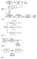
- Fig. 2
- ein Blockschaltbild einer Anordnung zur Erzeugung eines Einseitenbandsignals x(t);
- Fig. 3
- eine alternative Anordnung zur direkten digitalen Erzeugung des Einseitenbandsignals x(t);
- Fig. 4
- eine Darstellung zur empfangsseitigen Rückwandlung des Einseitenbandsignals x(t) in seine Komponenten ν(t) und ν ∧ (t);
- Fig. 5 und 6
- sende- bzw. empfangsseitige Maßnahmen zur Begrenzung des Sendespektrums duch Vorcodierung und Verwürfelung;
- Fig. 7
- eine Darstellung zur Detektierbarkeit von FSK-Signalen einer Dauer von Bruchteilen einer Sinusschwingung,
- Fig. 8
- eine AFSK-Demodulation mit geregelter AGC (automatic Gain Control)-Stufe;
- Fig. 9
- in der oberen Spur den Frequenzgang eines normalen Mittelungsfilters über eine Länge M=13 Werte und in der unteren Spur den Frequenzgang einer Zweifachkaskade mit gleicher Gesamtlänge;
- Fig. 10
- ein Blockschema einer Filterkaskade;
- Fig. 11
- das Übergangsverhalten für die Filteranordnungen, die den in Fig. 9 gezeigten Frequenzgängen zugrundeliegen;
- Fig. 12
- den prinzipiellen Aufbau eines PLL's als Tone Decoder;
- Fig. 13
- eine FSK-Demodulation mit PLL-Decodern,
- Fig. 14
- einen Sender für Codemultiplex, und
- Fig. 15
- einen Empfänger für Codemultiplex.
- Fig. 1
- a known approach of single sideband modulation of a real data signal ν (t);
- Fig. 2
- a block diagram of an arrangement for generating a single sideband signal x (t);
- Fig. 3
- an alternative arrangement for the direct digital generation of the single sideband signal x (t);
- Fig. 4
- a representation of the conversion on the receiving side of the single sideband signal x (t) into its components ν (t) and ν ∧ (t);
- 5 and 6
- measures on the transmission or reception side to limit the transmission spectrum by means of precoding and scrambling;
- Fig. 7
- a representation of the detectability of FSK signals with a duration of fractions of a sine wave,
- Fig. 8
- AFSK demodulation with regulated AGC (automatic gain control) stage;
- Fig. 9
- in the upper track the frequency response of a normal averaging filter over a length of M = 13 values and in the lower track the frequency response of a double cascade with the same overall length;
- Fig. 10
- a block diagram of a filter cascade;
- Fig. 11
- the transition behavior for the filter arrangements on which the frequency responses shown in FIG. 9 are based;
- Fig. 12
- the basic structure of a PLL as a tone decoder;
- Fig. 13
- FSK demodulation with PLL decoders,
- Fig. 14
- a transmitter for code division, and
- Fig. 15
- a receiver for code division multiplex.
Zur Erläuterung der Erfindung dienen die nachstehenden Lösungsschritte a) bis f):
In den Figuren 2 und 3 ist jeweils ein Controller dargestellt, der einen Festwertspeicher (ROM) adressiert, dem ein D/A-Wandler nachgeschaltet ist.FIGS. 2 and 3 each show a controller that has a read-only memory (ROM) addressed, which is followed by a D / A converter.
Entsprechend der in Fig. 2 gezeigten Struktur können sinus- oder cosinusförmig
verlaufende Signalpakete zur Bildung eines Mehrton-FSK-Signales verwendet werden,
die beispielsweise durch Auslesen des Festwertspeiches und anschließender
D/A-Wandlung generiert werden, wobei man durch versetzte Adressierung automatisch
das dazu hilberttransformierte Signal erhält. Anstelle der in Fig. 2 gezeigten
Modulation mit den Trägersignalen
In Fig. 4 ist gezeigt, daß nach Übertragung des so gebildeten Einseitenbandsignales x(t) über einen Datenkanal, in Fig. 4 als Kanal bezeichnet, nach geeigneter Vorfilterung eine Aufteilung in zwei Signalzweige durch Rückmodulation mit orthogonalen Sinus- und Cosinusschwingungen erfolgt, welche gegenüber der Sendeträgerfrequenzen einen geringen Kreisfrequenzversatz Δω0 und einen beliebigen Phasenversatz α aufweisen können. D. h. es ist keine Trägerfrequenzsynchronisation erforderlich, wie unten noch erläutert wird.In Fig. 4 it is shown that after transmission of the single sideband signal x (t) thus formed via a data channel, designated as a channel in Fig. 4, after suitable pre-filtering, a division into two signal branches takes place by back-modulation with orthogonal sine and cosine oscillations, which are compared the transmitter carrier frequencies can have a slight angular frequency offset Δω 0 and any phase offset α. That is, no carrier frequency synchronization is required, as will be explained below.
Nach Ausfilterung der doppelten Kreisfrequenzanteile hinter der Rückmodulation
durch geeignete Tiefpässe (Fig. 4) entstehen die beiden Signalkomponenten
Es werden also vorteilhaft ohne Einsatz der Hilbert-Transformation auf Sende- und
Empfangsseite zwei zueinander hilberttransformierte Signalzweige im Empfänger
erhalten. Das gilt vorteilhaft für beliebige Sendesignale v(t), wenn der Phasenversatz
α von Sende- und Empfangsträgerfrequenz z. B. durch einen Costas- oder
Squaring-Loop (Unsicherheit um π ist erlaubt) ausgeregelt wird, denn für α = 0°
wird
Wird zunächst nur ein Signal
Die Demodulation der Kreisfrequenz ω ν kann nach dem in DE 196 19 572 A1 beschriebenen
Verfahren zu
Wird im Sendesignalmodell nur ein Kanal invertiert, bzw. bei der Realisierung nach
Figur 3 das Signal
Die geschilderte Vorgehensweise entspricht bei der Berechnung von ϕ ˙(t) der Ermittlung der Draufsicht auf das Kurzzeitspektrum des FSK-Signales, und zwar ohne Umweg über die Berechnung von quadratischen Größen, wie es beispielsweise bei der Wigner-Verteilung und Derivaten davon erforderlich ist.The procedure described corresponds to the calculation when calculating ϕ ˙ (t) the top view of the short-term spectrum of the FSK signal, without Detour via the calculation of quadratic sizes, as is the case with the Wigner distribution and derivatives thereof is required.
Je zufälliger die Amplitude und Frequenz (und die Phase) durch das Datensignal
wechselnd stattfinden, umso begrenzter bleibt das Sendespektrum. Diese erzwungene
![]()
![]()
Durch die Einsparung der Hilbert-Transformation sowohl bei der Signalerzeugung als auch bei der Wiedergewinnung (Demodulation) des Datensignales ist es möglich, auch Bruchteile einer Sinusschwingung zur Informationsgewinnung zu benutzen, wie es beispielhaft in Figur 7 gezeigt ist. Fig. 7 zeigt eine Sinusschwingung und ein demoduliertes FSK-Signal mit Signaldauern von 1/10 Schwingungen.By saving the Hilbert transformation both in signal generation as well as in the recovery (demodulation) of the data signal, it is possible to use fractions of a sine wave for information acquisition, as shown by way of example in FIG. 7. Fig. 7 shows a sine wave and a demodulated FSK signal with signal durations of 1/10 vibrations.
Wird, wie schon erwähnt, das Sendesignal
Bei der Ermittlung der Momentankreisfrequenz ϕ ˙(t) wird nach einigen Zwischenrechnungen
das Ergebnis
In Fig. 8 ist dargestellt, daß das über den Datenkanal übertragene Einseitenbandsignal x(t) zweckmäßigerweise vor der Rückmodulation einer Bandpaßfilterung zur Rausch- und Störbefreiung unterzogen wird. Zur Regelanpassung folgt eine AGC (Automatic Gain Control)-Stufe, die logarithmisch, normal geregelt oder über eine geeignet aufgebrachte Amplitudenmodulation, die über z(t) detektiert werden kann, beeinflußt wird. Bandpaß und AGC können je nach Anwendungsfall auch in der Reihenfolge getauscht werden. Dann kann entweder erst eine Analog-Digitalwandlung folgen und rückmoduliert werden, s. Fig. 8, oder umgekehrt.8 shows that the single-sideband signal x ( t ) transmitted via the data channel is expediently subjected to bandpass filtering for noise and interference elimination before the back modulation. An AGC (Automatic Gain Control) stage follows for the rule adjustment, which is influenced logarithmically, normally or via a suitably applied amplitude modulation, which can be detected via z ( t ). Bandpass and AGC can also be exchanged in the order, depending on the application. Then either an analog-digital conversion can follow and be back-modulated, see Fig. 8, or vice versa.
Zur Detektion der FM-Information, d.h. zur Bestimmung, wann welche ω ν gesendet wurden, sind für die schnelle und bandbreiteneffiziente Datenübertragung geeignete Tiefpässe vorzusehen.To detect the FM information, ie to determine when which ω ν were sent, suitable low-pass filters must be provided for fast and bandwidth-efficient data transmission.
Je nach Anforderung an schnelle Wechsel der einzelnen Modulationskreisfrequenzen ω ν und entsprechendes schnelles Detektieren, d.h. schnelles Übergangsverhalten der Sprungantwort, können niedergradige digitale IIR-Filter (Infinite Impulse Response), linearphasige FIR-Filter (Finite Impulse Response) oder geeignet kaskadierte Mittelungsfilter eingesetzt werden.Depending on the requirements for rapid changes in the individual modulation circuit frequencies ω ν and corresponding rapid detection, i.e. fast transition behavior of the step response, low-grade digital IIR filters (Infinite Impulse Response), linear-phase FIR filters (Finite Impulse Response) or suitably cascaded averaging filters can be used.
Insbesondere der letzte Systemtyp bietet vorteilhaften Einsatz für schnelles Einschwingverhalten. The last system type in particular offers advantageous use for fast settling behavior.
Wird statt eines Mittelungsfilters über eine feste Länge M eine Aufteilung in eine Kaskadenanordung vorgenommen, so läßt sich die Rauschbefreiung der zu verarbeiteten Signale zugunsten eines schnellen Übergangsverhaltens beeinflussen.If instead of an averaging filter over a fixed length M a division into one Cascade arrangement made, so the noise can be processed Influence signals in favor of a fast transition behavior.
In Fig. 9 ist in der oberen Spur der Frequenzgang eines normalen Mittelungsfilters über M=13 Werte, in der unteren Spur der Frequenzgang einer Zweifachkaskade mit gleicher Gesamtlänge dargestellt.In Fig. 9, the frequency response of a normal averaging filter is in the upper track over M = 13 values, in the lower track the frequency response of a double cascade with same overall length.
Das Übergangsverhalten für beide, in Fig. 9 dargestellte Fälle, ist in Fig. 11 zu sehen.The transition behavior for both cases shown in FIG. 9 can be seen in FIG. 11.
Der Endwert wird bei Kaskadierung von Teilfiltern schneller erreicht, evtl. zu ungunsten der Rauschbefreiung im dB-Bereich.The final value is reached faster when cascading partial filters, possibly to the disadvantage noise suppression in the dB range.
Für durch Rauschen gestörte Empfangssignale läßt sich das für die Optimierung
notwendige Verfahren folgendermaßen erklären. Figur 10 zeigt ein Blockschaltbild
mit dem Nutzsignal x(t) und dem Störsignal n(t), welches auf die Filterkaskade
Bei Störung durch mittelwertfreies Rauschen, der Einfachheit als weiß angenommen,
läßt sich wegen der Linearität der Systeme zunächst die Reaktion für n(t) am
Ausgang, die Filterautokorrelation Φhh(τ) bestimmen.
Es ist
![]()
![]()
Für den Sonderfall τ=0 vereinfacht sich die Beziehung zu
Somit wird vom Rauschen (Störung) am Ausgang der Kaskade der Wert
Andererseits soll die Filterkaskade z.B. bei sprungförmigen Änderungen des Nutzsignals x(t) möglichst schnell auf den neuen Eingangswert einschwingen, beschreibbar durch die Sprungantwort der Filterkaskade und einen vorgebbaren Wert K mit K ≤ 1 als Bruchteil des neuen stationären Endwertes, z.B. 0,95. Die dazu erforderliche zu berechnende Zeit sei t an. Schnelles Einschwingen und gute Rauschbefreiung sind bezüglich der Filteraufgabe gegenläufige Forderungen.On the other hand, the filter cascade should, for example in the case of sudden changes in the useful signal x ( t ), settle as quickly as possible to the new input value, which can be described by the step response of the filter cascade and a predeterminable value K with K ≤ 1 as a fraction of the new stationary end value, for example 0.95. The required to be calculated time is t. Fast settling and good noise reduction are opposing requirements with regard to the filter task.
Es wird der Gütefaktor
Für viele Teilfilter in Kaskade strebt die Impulsantwort gegen einen gaußförmigen Verlauf. Ein solches Verhalten weist bekannterweise das beste Zeit-Bandbreiteprodukt auf.For many sub-filters in cascade, the impulse response strives against a Gaussian one Course. Such behavior is known to have the best time-bandwidth product on.
Eine Möglichkeit der Berechnung von z(t) und ϕ ˙(t) für die Signalauswertung für Amplituden- und Frequenzänderungen ω ν besteht darin, den APU-Teil (Arithmetik-Processor) einer heute gängigen CPU (z.B. Pentium-Prozessor) zu verwenden.One way of calculating z ( t ) and ϕ ˙ (t) for the signal evaluation for amplitude and frequency changes ω ν is to use the APU part (arithmetic processor) of a current CPU (e.g. Pentium processor).
Eine zweite Möglichkeit besteht darin, den bekannten CORDIC-Algorithmus einzusetzen,
der z.B. schon in
In Fig. 3 und den vorhergehenden Erklärungen wurde gezeigt, daß ein FSK-Sendesignal
in Einseitenbanddarstellung durch die Form
Das bekannte Strukturbild eines PLLs zur Frequenzsynchronisation oder zur FM-Demodulation wird um einen Quadraturkanal, wie in Fig. 12 dargestellt, erweitert. Wenn der PLL auf eine im Haltebereich befindliche Kreisfrequenz eingerastet ist, zeigt das der Lock Detect Comparator durch maximale Spannung an.The well-known structure of a PLL for frequency synchronization or FM demodulation is expanded by a quadrature channel, as shown in Fig. 12. If the PLL is locked to an angular frequency in the stop range, indicates that the Lock Detect Comparator shows maximum voltage.
Durch entsprechende Dimensionierung des PLL gelingt es, die Detektion einer vorhandenen Kreisfrequenz ω ν selbst bei nur Vorhandensein von 2 bis 3 Schwingungen vorzunehmen.By dimensioning the PLL appropriately, it is possible to detect an existing angular frequency ω ν even when there are only 2 to 3 vibrations.
Damit ist eine parallele PLL-Struktur zur Detektion eines Multiton-FSK-Signales realisierbar, s. Fig. 13, wobei jeder Decoderblock dem Strukturbild in Fig. 12 entsprechend aufgebaut ist.A parallel PLL structure for the detection of a multitone FSK signal can thus be implemented, s. FIG. 13, each decoder block corresponding to the structure picture in FIG. 12 is constructed.
Der weitere vorteilhafte Einsatz paralleler PLL-Filterbänke zur FSK-Demodulation besteht darin, daß trotz des normalen Bandpaßverhaltens eines einzelnen PLL-Kreises die Störimpulsantwort wesentlich kürzer ist, als sie ein Bandpaß mit der äquivalenten Rauschbandbreite besitzt. Diese Tatsache ist bereits durch umfangreiche Untersuchungen nachgewiesen und verbessert damit den Einsatz für die schnelle und bandbreiteneffiziente Datenübertragung mit FSK-Signalen.The further advantageous use of parallel PLL filter banks for FSK demodulation is that despite the normal bandpass behavior of a single PLL circuit the glitch response is much shorter than a bandpass with the equivalent noise bandwidth. This fact is already extensive Evidence proven and thus improves its use for fast and bandwidth-efficient data transmission with FSK signals.
Bei der Auswertung der Spektren von einem multifrequenten FSK- oder AFSK-Signal war festgestellt worden, daß bei Hinzunahme weiterer Frequenzen und zusätzlicher Modulationen (AFSK statt FSK) das Sendespektrum mehr in die Höhe und weniger in die Breite geht.When evaluating the spectra of a multi-frequency FSK or AFSK signal had been found that with the addition of additional frequencies and additional Modulations (AFSK instead of FSK) increase the transmission spectrum in height and less broad.
Dieser Effekt ist umso ausgeprägter, je zufälliger der Datenstrom und damit Frequenz- und Amplitudenwechsel vorgenommen werden. Diese Zufälligkeit kann durch bekannte Maßnahmen, wie Datenkomprimierung , Verwürfelung etc. unterstützt werden.This effect is all the more pronounced, the more random the data stream and thus frequency and amplitude changes are made. This randomness can be caused by Known measures such as data compression, scrambling etc. are supported.
In den Fig. 5 und 6 sind solche Maßnahmen statt der üblichen Quellencodierung eingesetzt. 5 and 6 are such measures instead of the usual source coding used.
Nach der Demodulation und der Rauschfilterung auf der Empfangsseite wird diese Verwürfelung durch die inversen Operationen wieder rückgängig gemacht.After demodulation and noise filtering on the receiving side, this becomes Scrambling reversed by the inverse operations.
Wird bei gewählten Amplituden und Kreisfrequenzen die zur Verfügung stehende Übertragungsbandbreite nur teilweise ausgenutzt, so kann das Sendespektrum mit Methoden der spektralen Spreizungstechnik, beispielsweise mit hochgetakteten Pseudo-Noise-Folgen und Derivaten aufgeweitet werden (CDMA = Code Division Multiple Access). Figuren 14 und 15 zeigen eine entsprechende beispielhafte Struktur einer solchen Anordnung.Will be the available at selected amplitudes and angular frequencies Transmission bandwidth is only partially used, so the transmission spectrum can Methods of spectral spreading technology, for example with highly clocked Pseudo-noise sequences and derivatives are expanded (CDMA = Code Division Multiple access). Figures 14 and 15 show a corresponding exemplary Structure of such an arrangement.
Zur Codesynchronisation können vorteilhaft bekannte Strukturen wie der Delay-Locked-Loop (DLL) eingesetzt werden.Known structures such as the delay-locked loop can advantageously be used for code synchronization (DLL) can be used.
Ein weiterer Vorteil spektral gespreizter Signale besteht darin, daß man mehrere Datenströme über den gleichen Kanal übertragen kann und diese durch Anwendung verschiedener Spreizungs- und Schlüsselfolgen eindeutig in verschiedenen Empfängern wieder entschlüsseln kann (Mehrfachausnutzung eines Datenkanals).Another advantage of spectrally spread signals is that you have several Data streams can be transmitted over the same channel and this through application different spreading and key sequences clearly in different recipients can decrypt again (multiple use of a data channel).
Claims (3)
- ω0 =
- Trägerfrequenz
- Δω =
- maximal 10-4·ω0
- α =
- eine beliebige Phasenverschiebung zwischen Trägersignal und Modulationssignal,
- ω 0 =
- Carrier frequency
- Δω =
- maximum 10 -4 · ω 0
- α =
- any phase shift between carrier signal and modulation signal,
Applications Claiming Priority (2)
| Application Number | Priority Date | Filing Date | Title |
|---|---|---|---|
| DE1998126253 DE19826253A1 (en) | 1998-06-15 | 1998-06-15 | Method for bandwidth-efficient multi-frequency data transmission |
| DE19826253 | 1998-06-15 |
Publications (2)
| Publication Number | Publication Date |
|---|---|
| EP0966131A2 true EP0966131A2 (en) | 1999-12-22 |
| EP0966131A3 EP0966131A3 (en) | 2002-07-03 |
Family
ID=7870719
Family Applications (1)
| Application Number | Title | Priority Date | Filing Date |
|---|---|---|---|
| EP99108998A Withdrawn EP0966131A3 (en) | 1998-06-15 | 1999-05-06 | Method of bandwidth-efficient multifrequency data transmission |
Country Status (2)
| Country | Link |
|---|---|
| EP (1) | EP0966131A3 (en) |
| DE (1) | DE19826253A1 (en) |
Cited By (3)
| Publication number | Priority date | Publication date | Assignee | Title |
|---|---|---|---|---|
| JP2019113360A (en) * | 2017-12-21 | 2019-07-11 | アイシン精機株式会社 | Distance measuring device |
| US11125874B2 (en) | 2017-12-21 | 2021-09-21 | Aisin Seiki Kabushiki Kaisha | Obstacle detection sensor |
| JP2022040288A (en) * | 2017-12-21 | 2022-03-10 | 株式会社アイシン | Distance measurement apparatus |
Citations (5)
| Publication number | Priority date | Publication date | Assignee | Title |
|---|---|---|---|---|
| US4485357A (en) * | 1981-03-09 | 1984-11-27 | U.S. Philips Corporation | Circuit for amplitude and phase modulation of carrier signal by two respective input signals |
| US4525862A (en) * | 1980-07-02 | 1985-06-25 | Motorola, Inc. | Transform modulation system |
| US4780884A (en) * | 1986-03-03 | 1988-10-25 | American Telephone And Telegraph Company, At&T Bell Laboratories | Suppressed double-sideband communication system |
| US5097218A (en) * | 1987-02-20 | 1992-03-17 | Cooper James C | Apparatus and method for multiplying the frequency of complex time varying signals |
| US5187719A (en) * | 1989-01-13 | 1993-02-16 | Hewlett-Packard Company | Method and apparatus for measuring modulation accuracy |
Family Cites Families (12)
| Publication number | Priority date | Publication date | Assignee | Title |
|---|---|---|---|---|
| DE1265236B (en) * | 1965-02-11 | 1968-04-04 | Siemens Ag | Single sideband modulator based on the phase shift method |
| US3560654A (en) * | 1969-02-25 | 1971-02-02 | Bell Telephone Labor Inc | Modulation and demodulation apparatus using reference time functions |
| US4090145A (en) * | 1969-03-24 | 1978-05-16 | Webb Joseph A | Digital quadrature demodulator |
| NL180369C (en) * | 1977-04-04 | 1987-02-02 | Philips Nv | DEVICE FOR CONVERTING DISCRETE SIGNALS TO A DISCREET SINGLE-BAND FREQUENCY-MULTIPLEX SIGNAL AND REVERSE. |
| US4479226A (en) * | 1982-03-29 | 1984-10-23 | At&T Bell Laboratories | Frequency-hopped single sideband mobile radio system |
| AT387679B (en) * | 1984-07-25 | 1989-02-27 | Sat Systeme Automatisierung | TRANSMITTER CIRCUIT FOR GENERATING FREQUENCY-MODULATED SIGNALS |
| DE3830729C2 (en) * | 1988-09-09 | 1998-04-09 | Hagenuk Marinekommunikation Gm | Method for generating a single sideband signal and circuit arrangement for carrying out the method |
| DE4302456A1 (en) * | 1993-01-29 | 1994-08-04 | Telefunken Sendertechnik | Modulation method and circuit for RF signals |
| DE4420376C2 (en) * | 1993-09-22 | 1998-09-17 | Hewlett Packard Co | Quadrature modulator |
| US5412351A (en) * | 1993-10-07 | 1995-05-02 | Nystrom; Christian | Quadrature local oscillator network |
| DE19535030A1 (en) * | 1994-10-21 | 1996-04-25 | Deutsche Telekom Ag | Quadrature amplitude modulation transmission system |
| DE19525844C2 (en) * | 1995-07-15 | 1998-08-13 | Telefunken Microelectron | Frequency conversion procedures |
-
1998
- 1998-06-15 DE DE1998126253 patent/DE19826253A1/en not_active Withdrawn
-
1999
- 1999-05-06 EP EP99108998A patent/EP0966131A3/en not_active Withdrawn
Patent Citations (5)
| Publication number | Priority date | Publication date | Assignee | Title |
|---|---|---|---|---|
| US4525862A (en) * | 1980-07-02 | 1985-06-25 | Motorola, Inc. | Transform modulation system |
| US4485357A (en) * | 1981-03-09 | 1984-11-27 | U.S. Philips Corporation | Circuit for amplitude and phase modulation of carrier signal by two respective input signals |
| US4780884A (en) * | 1986-03-03 | 1988-10-25 | American Telephone And Telegraph Company, At&T Bell Laboratories | Suppressed double-sideband communication system |
| US5097218A (en) * | 1987-02-20 | 1992-03-17 | Cooper James C | Apparatus and method for multiplying the frequency of complex time varying signals |
| US5187719A (en) * | 1989-01-13 | 1993-02-16 | Hewlett-Packard Company | Method and apparatus for measuring modulation accuracy |
Cited By (3)
| Publication number | Priority date | Publication date | Assignee | Title |
|---|---|---|---|---|
| JP2019113360A (en) * | 2017-12-21 | 2019-07-11 | アイシン精機株式会社 | Distance measuring device |
| US11125874B2 (en) | 2017-12-21 | 2021-09-21 | Aisin Seiki Kabushiki Kaisha | Obstacle detection sensor |
| JP2022040288A (en) * | 2017-12-21 | 2022-03-10 | 株式会社アイシン | Distance measurement apparatus |
Also Published As
| Publication number | Publication date |
|---|---|
| EP0966131A3 (en) | 2002-07-03 |
| DE19826253A1 (en) | 1999-12-16 |
Similar Documents
| Publication | Publication Date | Title |
|---|---|---|
| EP0208982B1 (en) | Digital branch filter for a data receiver | |
| DE2648273C2 (en) | Single sideband method for information transmission and device for carrying out the method | |
| EP0795982B1 (en) | Transmission system with quadrature modulation | |
| DE2309167C2 (en) | Method and circuit arrangement for correcting an electrical transmission signal corrupted by phase tremors | |
| EP0938782B1 (en) | Method of transmission and device to carry out said method | |
| EP1249114A2 (en) | Method and devices for transmitting and receiving information | |
| EP0080014A2 (en) | Digital demodulator for frequency-modulated signals | |
| DE10243141A1 (en) | Method for the transmission of optical polarization multiplex signals | |
| DE2918269A1 (en) | DIVERSITY SYSTEM | |
| DE1934296B2 (en) | Device for the transmission of rectangular synchronous information pulses | |
| EP1419583A1 (en) | Adaptive filtering method and filter for filtering a radio signal in a mobile radio-communication system | |
| DE1298120B (en) | Method and circuit arrangement for the coherent demodulation of synchronous, frequency-modulated Duobinaer signals | |
| DE69628130T2 (en) | Digital narrow band filter | |
| EP0966131A2 (en) | Method of bandwidth-efficient multifrequency data transmission | |
| CH669489A5 (en) | ||
| EP0795983A1 (en) | OQPSK modulator | |
| DE69937018T2 (en) | RDS demodulator for the reception of radio programs containing radio data signals and motorists radio information signals (ARI), with a digital filter device which causes a high attenuation of the ARI signal | |
| DE2845210C2 (en) | ||
| DE3010537A1 (en) | ARRANGEMENT FOR TRANSMITTING DIGITAL DATA | |
| DE4244144C1 (en) | Demodulating FM signals esp. in ultra short wave range - sampling received signal and passing sampled signal through band filter with complex value coeffts. | |
| EP0602435B1 (en) | Demodulation method for frequency-modulated signals | |
| EP0617507B1 (en) | Frequency modulated signals demodulation method | |
| DE10260403B4 (en) | RDS decoder | |
| DE2653970A1 (en) | MESSAGE TRANSFER PROCEDURE | |
| DE3246145A1 (en) | TELEVISION TRANSMISSION SYSTEM WITH INTEGRATED TRANSMISSION OF ADDITIONAL INFORMATION, IN PARTICULAR SOUND SIGNALS |
Legal Events
| Date | Code | Title | Description |
|---|---|---|---|
| PUAI | Public reference made under article 153(3) epc to a published international application that has entered the european phase |
Free format text: ORIGINAL CODE: 0009012 |
|
| AK | Designated contracting states |
Kind code of ref document: A2 Designated state(s): AT BE CH CY DE DK ES FI FR GB GR IE IT LI LU MC NL PT SE |
|
| AX | Request for extension of the european patent |
Free format text: AL;LT;LV;MK;RO;SI |
|
| RAP1 | Party data changed (applicant data changed or rights of an application transferred) |
Owner name: ABB PATENT GMBH |
|
| PUAL | Search report despatched |
Free format text: ORIGINAL CODE: 0009013 |
|
| AK | Designated contracting states |
Kind code of ref document: A3 Designated state(s): AT BE CH CY DE DK ES FI FR GB GR IE IT LI LU MC NL PT SE |
|
| AX | Request for extension of the european patent |
Free format text: AL;LT;LV;MK;RO;SI |
|
| RIC1 | Information provided on ipc code assigned before grant |
Free format text: 7H 04L 27/02 A, 7H 04L 27/38 B, 7H 04L 27/32 B, 7H 04B 1/30 B, 7H 04B 1/68 B |
|
| AKX | Designation fees paid |
Designated state(s): AT CH DE FR LI |
|
| STAA | Information on the status of an ep patent application or granted ep patent |
Free format text: STATUS: THE APPLICATION IS DEEMED TO BE WITHDRAWN |
|
| 18D | Application deemed to be withdrawn |
Effective date: 20030104 |