EP0966084B1 - Method for controlling the triggering of a safety device in a high voltage generator and high voltage generator using such method - Google Patents
Method for controlling the triggering of a safety device in a high voltage generator and high voltage generator using such method Download PDFInfo
- Publication number
- EP0966084B1 EP0966084B1 EP99401455A EP99401455A EP0966084B1 EP 0966084 B1 EP0966084 B1 EP 0966084B1 EP 99401455 A EP99401455 A EP 99401455A EP 99401455 A EP99401455 A EP 99401455A EP 0966084 B1 EP0966084 B1 EP 0966084B1
- Authority
- EP
- European Patent Office
- Prior art keywords
- value
- high voltage
- voltage
- max
- tripping
- Prior art date
- Legal status (The legal status is an assumption and is not a legal conclusion. Google has not performed a legal analysis and makes no representation as to the accuracy of the status listed.)
- Expired - Lifetime
Links
Images

Classifications
-
- H—ELECTRICITY
- H02—GENERATION; CONVERSION OR DISTRIBUTION OF ELECTRIC POWER
- H02H—EMERGENCY PROTECTIVE CIRCUIT ARRANGEMENTS
- H02H7/00—Emergency protective circuit arrangements specially adapted for specific types of electric machines or apparatus or for sectionalised protection of cable or line systems, and effecting automatic switching in the event of an undesired change from normal working conditions
- H02H7/003—Emergency protective circuit arrangements specially adapted for specific types of electric machines or apparatus or for sectionalised protection of cable or line systems, and effecting automatic switching in the event of an undesired change from normal working conditions for electrostatic apparatus
-
- B—PERFORMING OPERATIONS; TRANSPORTING
- B05—SPRAYING OR ATOMISING IN GENERAL; APPLYING FLUENT MATERIALS TO SURFACES, IN GENERAL
- B05B—SPRAYING APPARATUS; ATOMISING APPARATUS; NOZZLES
- B05B5/00—Electrostatic spraying apparatus; Spraying apparatus with means for charging the spray electrically; Apparatus for spraying liquids or other fluent materials by other electric means
- B05B5/08—Plant for applying liquids or other fluent materials to objects
- B05B5/10—Arrangements for supplying power, e.g. charging power
Definitions
- the invention relates to a method for controlling safety tripping means in a high voltage generator more specifically designed for electrostatic applications of coating products, the safety tripping means having the function of interrupting the development of the high voltage when there is a risk of discharge in the form of an electric arc.
- the invention also relates to a high voltage generator provided with safety tripping means implementing such a method.
- the known safety systems operate by continuously measuring the value of the current delivered by the generator, by developing from it at least one current parameter and comparing it to a threshold.
- current parameter is meant for example the value of the current I itself at a given moment when its variation (ie the derivative of the current with respect to time d I d t ).
- these two parameters at least are taken into account for the evaluation of the risks of discharge in the form of electric arc.
- the current parameter is the current itself, it is compared to a maximum current value I max. If the current parameter is the variation of the current (derivative), it is compared to a maximum current variation value (dI / dt max). If said current parameter exceeds the preset limit value, a signal or information is developed to control safety tripping means able to cut the high voltage or inhibit the generator, to prevent the formation of the electric arc.
- the authorized value of energy coming from a projector of product of coating is becoming weaker, typically 0.24 mJ for a liquid paint and 5 mJ for a powder paint. It is therefore necessary to develop increasingly sensitive and rapid security systems, while remaining effective, that is to say not causing unwarranted unjustified triggering.
- a critical situation can be caused when there is a sudden approximation between the object to be covered and the end of the projector brought to the high voltage. This is for example often the case in the electrostatic application of coating product on moving objects along a conveyor, the projectors being placed on the side of this conveyor. It may happen that a protruding part of the object to be painted passes near the projector, creating a risk of discharge in the form of an electric arc. The latter can be the cause of a fire, especially in the case of application of solvent paint.
- the problem of treating an automobile body By way of example, mention may be made of the problem of treating an automobile body.
- the fuel door of the vehicle is left open. If it passes very close to an electrostatic spraying device, the control means associated with the generator detect an abnormal increase in the current, which can result in a disjunction.
- the voltage rise of the generator is conventionally performed with inhibition of the safety tripping means during a predetermined time interval. In other words, at the beginning of the voltage rise of the generator, these tripping means can no longer intervene and prevent a discharge in the form of an electric arc. If the fuel filler flap is still near the floodlight during this voltage recovery phase, several electric arcs may occur between the coating product spraying device and the fuel filler flap. In certain circumstances, these arcs can cause a fire.
- the invention overcomes these difficulties. More specifically, the invention relates to a method for controlling safety tripping means in a high voltage generator, in particular for electrostatic coating product application, the tripping means being able to interrupt the development of the high voltage when appears a risk of discharge in the form of an electric arc, consisting in activating the safety tripping means when at least one current parameter reaches a threshold, characterized in that it consists in varying such a threshold according to a predetermined variation law depending on the value of the high voltage.
- the current parameter in the sense defined above, can be the value of the current itself. It can also be the value of the variation of this current (that is to say the derivative of the current with respect to time: dI / dt)
- the two parameters will be exploited jointly by defining for each a law of variation predetermined according to the value of the high voltage.
- the safety tripping means are inhibited when the high voltage is lower than a predetermined minimum value.
- the inhibition of safety during the voltage rise phase is no longer set by a time delay but depends only on the fact that a minimum of high voltage has or has not been reached.
- This feature has an additional advantage. Indeed, on most generators, the rise ramp of the high voltage is adjustable. Therefore, by choosing to release the safety systems as soon as a minimum voltage is reached, the inhibition is made independent of the voltage rise ramp setting.
- the invention also relates to a high voltage generator comprising means for developing a high voltage and safety tripping means for switching off the high voltage when a risk of discharge in the form of an electric arc appears, characterized in that includes means for developing variable trigger information in depending on the value of the high voltage, this triggering information being associated with a given current parameter and comparison means for comparing said triggering information with another information representative of said current parameter itself, the comparison means elaborating in response a control information of said safety release means.
- This generator may advantageously furthermore comprise comparison means making it possible to compare information representative of the high voltage with information representing a minimum voltage, the comparison means developing in response control information of means for inhibiting the means of security trigger. It should also be noted that these inhibition means can operate independently of the fact that a trigger threshold can be varied as a function of the value of the high voltage, as indicated above.
- the high voltage generator as just described, and more particularly the safety tripping means that it comprises can equally well be made by conventional electronic circuits analogically processing the current and voltage taken from the generator or by digital processing using a microprocessor, its memories and a wired logic, since the current and voltage signals have been converted into digital data.
- the term "information" used in the foregoing definition refers indifferently and generically to an analog signal processed as such or a digital data representing such a signal.
- FIG. 1 shows the essential elements of a high-voltage generator 11 which can be divided into two subassemblies, a fixed-station subassembly 12 and a mobile subassembly 13 integrated into an electrostatic projection device. coating product not shown, the two subassemblies being interconnected by a strand of electrical wires 14.
- the stationary subassembly comprises, connected in cascades, a rectifier 16, a DC-DC converter 17 and a converter Continuous-rectifier 18.
- the rectifier is intended to be connected to the AC distribution circuit CA.
- the DC-DC converter 17 is controlled by a voltage control circuit 19, of a conventional type, which makes it possible in particular to control the rise in voltage at start-up.
- This converter thus provides an adjustable DC voltage with a progressive rise to the DC-AC converter 18.
- the voltage rise control circuit is itself controlled by a control circuit 20 receiving inter alia a variable reference voltage Uc.
- the reference voltage Uc can be produced in the circuit 20 itself.
- the output of the DC-AC converter is connected to the primary winding 21p of a step-up transformer, via a contact 24 of a relay 25 controlled by the control circuit 20.
- the secondary winding 21s of the transformer 22 is connected to a voltage multiplier circuit 27 of the capacitor and diode type commonly called "cascade circuit".
- the output of this voltage multiplier is connected to the high voltage output SHT of the generator, via a protection resistor R.
- a measurement resistor R1 is connected between one end of the secondary winding 21s and the ground of the device.
- the resistor R1 is preferably located in the subassembly 12, in particular in the control circuit 20 via a conductor 30 extending between the subassemblies 12 and 13.
- the assembly constituted by the secondary winding 21s and the voltage multiplier circuit 27 constitutes a high voltage generator dipole extending between the ground and the output SHT, it appears that the current flowing to the load connected to this output is also the current flowing through the resistor R1. Therefore, the The voltage that develops across this resistor is representative of the high voltage current I.
- the output of the voltage multiplier 27 is also connected to a conductor 32 via a measuring and discharging resistor R2. The voltage available between this conductor 32 and the ground is therefore representative of the value of the high voltage U.
- the two conductors 30, 32 form part of the strand 14 and are connected to the control circuit 20 forming part of the subassembly 12.
- FIG. 2 describes in more detail the subassembly dealing with safety in the control circuit 20.
- the inputs are the two conductors 30, 32 for measuring the high voltage current and the high voltage itself.
- the circuit contains the electrical part of the relay 25 whose contact 24 is in series between the output of the DC-to-AC converter 18 and the primary winding 21 p of the step-up transformer.
- the control circuit contains safety trip means 36 for turning off the high voltage when there is a risk of arc discharge.
- the safety trigger results in the opening of the contact 24 of the relay 25, that is to say by the control of the electromagnetic part of this relay, to open the contact 24.
- the safety tripping means comprise means for generating at least one trigger information I max and / or d I d t max variable depending on the value of the high voltage U.
- the signals representative of these two parameters are respectively applied to inputs of different comparison means.
- the input driver 30 is directly applied to an input of a comparator 38 while the output of the differentiator circuit 37 is directly applied to an input of a comparator 39.
- the outputs of these comparators are respectively connected to two inputs of a gate 40 of the OR type whose output drives the relay 25, via an amplifier 40.
- the means for producing a variable triggering information as a function of the value of the high voltage, with regard to the current parameter constituted by the current I itself, comprises a circuit generating a triggering information 45, variable according to the the value of the high voltage U and whose output S1 is applied to the other input of the comparator 38.
- This generator circuit 45 has three inputs, one connected to the voltage input conductor 32, the second connected to a adjustable voltage setpoint Uc which represents the value of the desired high voltage and the third connected to a setpoint I max, adjustable, which represents the maximum value of the current which one wishes not to exceed when the high voltage has reaches the Uc value.
- the triggering information delivered by the circuit 45 is denoted I max (t)
- d I d t comprises a circuit generating a trigger information 46, variable as a function of the value of the high voltage U and whose output S2 is applied to the other input of the comparator 39.
- This generator circuit 46 has three inputs, the one connected to the voltage input lead 32, the second connected to the adjustable voltage setpoint Uc which represents the value of the desired high voltage and the third connected to a maximum current variation setpoint.
- d I d t max which represents the maximum value of the variation of the current (derivative with respect to time) which one does not wish to exceed when the high voltage has reached the value Uc.
- the triggering information delivered by the circuit 46 is noted d I d t max ( t ).
- the thresholds each vary according to a predetermined variation law, here linear as a function of the value of the high voltage and as long as it is lower than the chosen value Uc.
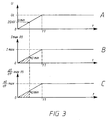
- the curve A represents the voltage rise of the generator, up to the value Uc, under the control of the circuit 19. It can be seen that the voltage rises gradually and here linearly for a given period of time. At time t 1 , the value of the high voltage reaches the chosen value and in principle, it must remain constant throughout the duration of use.
- the curve B shows the evolution of the tripping information I max (t) produced by the circuit 45. It can be seen that the tripping threshold varies substantially in the same proportions as the evolution of the high voltage. herself. Therefore, especially during the voltage rise of the generator, a safety trip may occur for a current I less than I max.
- curve C shows the evolution of the triggering information d I d t max ( t ) developed by the circuit 46. It can be seen that the tripping threshold changes substantially like the high voltage. Consequently, a security trigger may occur, in particular during the start-up phase, for a variation of current d I d t lower than d I d t max.
- comparison means 48 for comparing information representative of the high voltage to information representative of a minimum voltage U min.
- U min is a simple comparator 48 whose input is connected to the conductor 32 and whose other input is connected to a minimum voltage reference U min, here set at 20 kV. In practice, U min should be set to the lowest possible value for obvious security reasons.
- the output of the comparator 48 is connected to a means of inhibition 49 of the safety tripping means, for example inserted between the output of the amplifier 41 and the relay 25.
- the relay 25 can not be controlled, at the opening which allows in particular to absorb without disjunct the current peak corresponding to the rise of the voltage multiplier 27 and wait to be able to "read" measurable current values.
- the measurement of the high voltage level HT can be carried out in another way than that described.
- the conductor 32 is connected to the output of the converter 18 or to the output of the circuit 19.
- the resistor R2 may be deleted, which is advantageous, if the mobile subassembly 13 is of the manual type, in particular.
Landscapes
- Electrostatic Spraying Apparatus (AREA)
- Emergency Protection Circuit Devices (AREA)
- Control Of Voltage And Current In General (AREA)
- Application Of Or Painting With Fluid Materials (AREA)
Description
L'invention concerne un procédé de commande de moyens de déclenchement de sécurité dans un générateur de haute tension plus particulièrement conçu pour les applications électrostatiques de produits de revêtement, les moyens de déclenchement de sécurité ayant pour fonction d'interrompre l'élaboration de la haute tension lorsque apparaît un risque de décharge sous forme d'arc électrique. L'invention concerne également un générateur de haute tension pourvu de moyens de déclenchement de sécurité mettant en oeuvre un tel procédé.The invention relates to a method for controlling safety tripping means in a high voltage generator more specifically designed for electrostatic applications of coating products, the safety tripping means having the function of interrupting the development of the high voltage when there is a risk of discharge in the form of an electric arc. The invention also relates to a high voltage generator provided with safety tripping means implementing such a method.
Lors de l'application d'un produit de revêtement par voie électrostatique où des particules de produit de revêtement sont chargées à l'aide d'un générateur de haute tension, il est impératif de détecter et éliminer des situations potentiellement dangereuses qui peuvent se traduire par des décharges brutales sous forme d'arc électrique s'établissant, dans certaines conditions, entre le dispositif de projection de produit de revêtement et la pièce à recouvrir, celle-ci étant généralement métallique et électriquement reliée à la terre. Les systèmes de sécurité connus fonctionnent en mesurant en permanence la valeur du courant délivré par le générateur, en élaborant à partir de celui-ci au moins un paramètre de courant et en comparant ce dernier à un seuil. Par "paramètre de courant", on entend par exemple la valeur du courant I lui-même à un moment donné où sa variation (c'est-à-dire la dérivée du courant par rapport au temps ![]()
![]()
Selon les nouvelles normes en vigueur, la valeur autorisée d'énergie issue d'un projecteur de produit de revêtement est de plus en plus faible, typiquement 0,24 mJ pour une peinture liquide et 5 mJ pour une peinture en poudre. Il est donc nécessaire de mettre au point des systèmes de sécurité de plus en plus sensibles et rapides, tout en restant efficaces, c'est-à-dire n'occasionnant pas des déclenchements intempestifs non justifiés.According to the new standards in force, the authorized value of energy coming from a projector of product of coating is becoming weaker, typically 0.24 mJ for a liquid paint and 5 mJ for a powder paint. It is therefore necessary to develop increasingly sensitive and rapid security systems, while remaining effective, that is to say not causing unwarranted unjustified triggering.
Une situation critique peut être occasionnée lorsque intervient un brusque rapprochement entre l'objet à recouvrir et l'extrémité du projecteur porté à la haute tension. Ceci est par exemple souvent le cas dans l'application électrostatique de produit de revêtement sur des objets en défilement le long d'un convoyeur, les projecteurs étant placés sur le côté de ce convoyeur. Il peut arriver qu'une partie en saillie de l'objet à peindre passe à proximité du projecteur, créant un risque de décharge sous forme d'arc électrique. Ce dernier peut être à l'origine d'un incendie, notamment dans le cas d'application de peinture solvantée.A critical situation can be caused when there is a sudden approximation between the object to be covered and the end of the projector brought to the high voltage. This is for example often the case in the electrostatic application of coating product on moving objects along a conveyor, the projectors being placed on the side of this conveyor. It may happen that a protruding part of the object to be painted passes near the projector, creating a risk of discharge in the form of an electric arc. The latter can be the cause of a fire, especially in the case of application of solvent paint.
A titre d'exemple, on peut citer le problème du traitement d'une carrosserie d'automobile. Au cours du processus de revêtement, la trappe à essence du véhicule est laissée ouverte. Si celle-ci passe très près d'un dispositif de pulvérisation électrostatique, les moyens de contrôle associés au générateur détectent une augmentation anormale du courant, ce qui peut se traduire par une disjonction. Lors du réarmement, la remontée en tension du générateur s'opère classiquement avec inhibition des moyens de déclenchement de sécurité pendant un intervalle de temps prédéterminé. Autrement dit, au début de la remontée en tension du générateur, ces moyens de déclenchement ne peuvent plus intervenir et empêcher une décharge sous forme d'arc électrique. Si la trappe à essence est toujours à proximité du projecteur pendant cette phase de rétablissement de la tension, plusieurs arcs électriques peuvent se produire entre le dispositif de projection de produit de revêtement et la trappe à essence de la carrosserie. Dans certaines circonstances, ces arcs électriques peuvent être à l'origine d'un incendie.By way of example, mention may be made of the problem of treating an automobile body. During the coating process, the fuel door of the vehicle is left open. If it passes very close to an electrostatic spraying device, the control means associated with the generator detect an abnormal increase in the current, which can result in a disjunction. During rearming, the voltage rise of the generator is conventionally performed with inhibition of the safety tripping means during a predetermined time interval. In other words, at the beginning of the voltage rise of the generator, these tripping means can no longer intervene and prevent a discharge in the form of an electric arc. If the fuel filler flap is still near the floodlight during this voltage recovery phase, several electric arcs may occur between the coating product spraying device and the fuel filler flap. In certain circumstances, these arcs can cause a fire.
Parmi les tests normalisés ou classiquement utilisés pour évaluer le comportement d'un système de sécurité vis-à-vis d'un problème de ce type, on peut mentionner celui qui consiste à placer une sphère à quelques centimètres de l'extrémité sous haute tension d'un pulvérisateur et à enclencher la haute tension. On constate que la plupart des systèmes actuels ne permettent pas d'éviter des décharges sous forme d'arc électrique aux valeurs d'énergie mentionnées ci-dessus. Un procédé de commande selon l'état de la technique est connu duAmong the standardized tests or conventionally used to evaluate the behavior of a security system vis-à-vis a problem of this type, there may be mentioned that of placing a sphere a few centimeters from the end under high voltage of a sprayer and to snap the high voltage. It can be seen that most current systems do not make it possible to avoid discharges in the form of an electric arc at the energy values mentioned above. A control method according to the state of the art is known to
document
L'invention permet de surmonter ces difficultés. Plus précisément, l'invention concerne un procédé de commande de moyens de déclenchement de sécurité dans un générateur de haute tension, notamment pour application électrostatique de produit de revêtement, les moyens de déclenchement étant aptes à interrompre l'élaboration de la haute tension lorsque apparaît un risque de décharge sous forme d'arc électrique, consistant à activer les moyens de déclenchement de sécurité lorsque au moins un paramètre de courant atteint un seuil, caractérisé en ce qu'il consiste à faire varier un tel seuil selon une loi de variation prédéterminée en fonction de la valeur de la haute tension.The invention overcomes these difficulties. More specifically, the invention relates to a method for controlling safety tripping means in a high voltage generator, in particular for electrostatic coating product application, the tripping means being able to interrupt the development of the high voltage when appears a risk of discharge in the form of an electric arc, consisting in activating the safety tripping means when at least one current parameter reaches a threshold, characterized in that it consists in varying such a threshold according to a predetermined variation law depending on the value of the high voltage.
Le paramètre de courant, au sens défini plus haut, peut être la valeur du courant lui-même. Il peut être aussi la valeur de la variation de ce courant (c'est-à-dire la dérivée du courant par rapport au temps : dI/dt. De préférence, les deux paramètres seront exploités conjointement en définissant pour chacun une loi de variation prédéterminée en fonction de la valeur de la haute tension.The current parameter, in the sense defined above, can be the value of the current itself. It can also be the value of the variation of this current (that is to say the derivative of the current with respect to time: dI / dt) Preferably, the two parameters will be exploited jointly by defining for each a law of variation predetermined according to the value of the high voltage.
Selon une autre caractéristique notable, les moyens de déclenchement de sécurité sont inhibés lorsque la haute tension est inférieure à une valeur minimum prédéterminée. Autrement dit, l'inhibition des sécurités pendant la phase de montée en tension n'est plus fixée par une temporisation mais dépend seulement du fait qu'un minimum de haute tension a ou non été atteint. Cette particularité présente un avantage supplémentaire. En effet, sur la plupart des générateurs, la rampe de montée de la haute tension est réglable. Par conséquent, en choisissant de libérer les systèmes de sécurité dès qu'un minimum de tension est atteint, on rend l'inhibition indépendante du réglage de la rampe de montée en tension.According to another notable characteristic, the safety tripping means are inhibited when the high voltage is lower than a predetermined minimum value. In other words, the inhibition of safety during the voltage rise phase is no longer set by a time delay but depends only on the fact that a minimum of high voltage has or has not been reached. This feature has an additional advantage. Indeed, on most generators, the rise ramp of the high voltage is adjustable. Therefore, by choosing to release the safety systems as soon as a minimum voltage is reached, the inhibition is made independent of the voltage rise ramp setting.
L'invention concerne également un générateur de haute tension comprenant des moyens pour élaborer une haute tension et des moyens de déclenchement de sécurité pour couper la haute tension lorsqu'un risque de décharge sous forme d'arc électrique apparaît, caractérisé en ce qu'il comprend des moyens pour élaborer une information de déclenchement variable en fonction de la valeur de la haute tension, cette information de déclenchement étant associée à un paramètre de courant donné et des moyens de comparaison pour comparer ladite information de déclenchement à une autre information représentative dudit paramètre de courant lui-même, les moyens de comparaison élaborant en réponse une information de commande desdits moyens de déclenchement de sécurité.The invention also relates to a high voltage generator comprising means for developing a high voltage and safety tripping means for switching off the high voltage when a risk of discharge in the form of an electric arc appears, characterized in that includes means for developing variable trigger information in depending on the value of the high voltage, this triggering information being associated with a given current parameter and comparison means for comparing said triggering information with another information representative of said current parameter itself, the comparison means elaborating in response a control information of said safety release means.
Ce générateur peut avantageusement comporter en outre des moyens de comparaison permettant de comparer une information représentative de la haute tension à une information représentative d'une tension minimum, les moyens de comparaison élaborant en réponse une information de commande de moyens d'inhibition des moyens de déclenchement de sécurité. Il est à noter d'ailleurs que ces moyens d'inhibition peuvent opérer indépendamment du fait que l'on peut faire varier un seuil de déclenchement en fonction de la valeur de la haute tension, comme indiqué ci-dessus.This generator may advantageously furthermore comprise comparison means making it possible to compare information representative of the high voltage with information representing a minimum voltage, the comparison means developing in response control information of means for inhibiting the means of security trigger. It should also be noted that these inhibition means can operate independently of the fact that a trigger threshold can be varied as a function of the value of the high voltage, as indicated above.
Il est également à noter que le générateur de haute tension tel qu'il vient d'être décrit et plus particulièrement les moyens de déclenchement de sécurité qu'il comporte, peuvent indifféremment être réalisés par des circuits électroniques classiques traitant de façon analogique les signaux de courant et de tension prélevés sur le générateur ou bien par un traitement numérique à l'aide d'un microprocesseur, de ses mémoires et d'une logique câblée, dès lors que les signaux de courant et de tension ont été convertis en données numériques. Le terme "information" utilisé dans la définition qui précède désigne indifféremment et de façon générique un signal analogique traité en tant que tel ou une donnée numérique représentant un tel signal.It should also be noted that the high voltage generator as just described, and more particularly the safety tripping means that it comprises, can equally well be made by conventional electronic circuits analogically processing the current and voltage taken from the generator or by digital processing using a microprocessor, its memories and a wired logic, since the current and voltage signals have been converted into digital data. The term "information" used in the foregoing definition refers indifferently and generically to an analog signal processed as such or a digital data representing such a signal.
L'invention sera mieux comprise et d'autres avantages de celle-ci apparaîtront plus clairement à la lumière de la description qui va suivre, donnée uniquement à titre d'exemple et faite en référence aux dessins annexés dans lesquels :
- la figure 1 est un schéma-bloc général d'un générateur de haute tension pourvu du perfectionnement conforme à l'invention ;
- la figure 2 est un schéma-bloc particulier des moyens de commande de déclenchement de sécurité intégrés au générateur de la figure 1 ; et
- la figure 3 est un graphe illustrant le fonctionnement du générateur, notamment pendant la montée en tension de celui-ci.
- Figure 1 is a general block diagram of a high voltage generator provided with the improvement according to the invention;
- FIG. 2 is a particular block diagram of the safety tripping control means integrated into the generator of FIG. 1; and
- Figure 3 is a graph illustrating the operation of the generator, especially during the voltage rise thereof.
Sur la figure 1, on a représenté les éléments essentiels d'un générateur haute tension 11 qui peut se diviser en deux sous-ensembles, un sous-ensemble à poste fixe 12 et un sous-ensemble mobile 13 intégré à un dispositif de projection électrostatique de produit de revêtement non représenté, les deux sous-ensembles étant reliés entre eux par un toron de fils électriques 14. Le sous-ensemble à poste fixe comporte, reliés en cascades, un redresseur 16, un convertisseur continu-continu 17 et un convertisseur continu-alternatif 18. Le redresseur est destiné à être relié au circuit de distribution de courant alternatif C.A.. Le convertisseur continu-continu 17 est piloté par un circuit de contrôle de tension 19 , d'un type classique, qui permet notamment de contrôler la montée en tension, au démarrage. Ce convertisseur fournit donc une tension continue réglable et à montée progressive au convertisseur continu-alternatif 18. Le circuit de contrôle de montée en tension est lui-même piloté par un circuit de commande 20 recevant entre autres une tension de consigne Uc, variable. Selon une variante, la tension de consigne Uc peut être élaborée dans le circuit 20 lui-même. La sortie du convertisseur continu-alternatif est reliée à l'enroulement primaire 21p d'un transformateur-élévateur, via un contact 24 d'un relais 25 piloté par le circuit de commande 20. L'enroulement secondaire 21s du transformateur 22 est connecté à un circuit multiplicateur de tension 27 du type à condensateurs et diodes communément appelé "circuit cascade". La sortie de ce multiplicateur de tension est reliée à la sortie haute tension SHT du générateur, via une résistance de protection R. Une résistance de mesure R1 est connectée entre une extrémité de l'enroulement secondaire 21s et la masse du dispositif. La résistance R1 est de préférence située dans le sous-ensemble 12, notamment dans le circuit de commande 20 via un conducteur 30 s'étendant entre les sous-ensembles 12 et 13. Si on considère que l'ensemble constitué par l'enroulement secondaire 21s et le circuit multiplicateur de tension 27 constitue un dipôle générateur de haute tension s'étendant entre la masse et la sortie SHT, il apparaît que le courant qui s'écoule vers la charge connectée à cette sortie est aussi le courant qui traverse la résistance R1. Par conséquent, la tension qui se développe aux bornes de cette résistance est représentative du courant haute tension I. La sortie du multiplicateur de tension 27 est également reliée à un conducteur 32 par l'intermédiaire d'une résistance de mesure et de décharge R2. La tension disponible entre ce conducteur 32 et la masse est donc représentative de la valeur de la haute tension U. Les deux conducteurs 30, 32 font partie du toron 14 et sont connectés au circuit de commande 20 faisant partie du sous-ensemble 12.FIG. 1 shows the essential elements of a high-voltage generator 11 which can be divided into two subassemblies, a fixed-
La figure 2 décrit plus en détail le sous-ensemble traitant de la sécurité dans le circuit de commande 20. On retrouve en entrées les deux conducteurs 30, 32 permettant la mesure du courant haute tension et de la haute tension elle-même. Le circuit renferme la partie électrique du relais 25 dont le contact 24 est en série entre la sortie du convertisseur continu-alternatif 18 et l'enroulement primaire 21 p du transformateur-élévateur. Le circuit de commande renferme des moyens de déclenchement de sécurité 36 pour couper la haute tension lorsqu'un risque de décharge sous forme d'arc électrique apparaît. Le déclenchement de sécurité se traduit par l'ouverture du contact 24 du relais 25, c'est-à-dire par la commande de la partie électromagnétique de ce relais, pour ouvrir le contact 24.FIG. 2 describes in more detail the subassembly dealing with safety in the
Dans l'exemple représenté, les moyens de déclenchement de sécurité comprennent des moyens pour élaborer au moins une information de déclenchement I max et/ou ![]()
![]()
![]()
![]()
Les moyens pour élaborer une information de déclenchement variable en fonction de la valeur de la haute tension, pour ce qui concerne le paramètre de courant constitué par le courant I lui-même comprend un circuit générateur d'une information de déclenchement 45, variable en fonction de la valeur de la haute tension U et dont la sortie S1 est appliquée à l'autre entrée du comparateur 38. Ce circuit générateur 45 comporte trois entrées, l'une reliée au conducteur 32 d'entrée de tension, la seconde reliée à une consigne de tension réglable Uc qui représente la valeur de la haute tension que l'on désire et la troisième reliée à une consigne I max, réglable, qui représente la valeur maximum du courant que l'on désire ne pas dépasser lorsque la haute tension a atteint la valeur Uc. L'information de déclenchement délivrée par le circuit 45 est notée I max(t)The means for producing a variable triggering information as a function of the value of the high voltage, with regard to the current parameter constituted by the current I itself, comprises a circuit generating a triggering
De façon semblable, les moyens pour élaborer une information de déclenchement variable en fonction de la valeur de la haute tension, pour ce qui concerne le paramètre de courant constitué par la variation de courant ![]()
![]()
![]()
![]()
![]()
![]()
Le circuit 45, dont la conception est à la portée de l'homme du métier élabore un signal ou une information représentatif d'un premier seuil variable du type : 
De même, le circuit 46 élabore un signal ou une information constituant un second seuil correspondant à la variation du courant, du type : 
Autrement dit, les seuils varient chacun selon une loi de variation prédéterminée, ici linéaire en fonction de la valeur de la haute tension et tant que celle-ci est inférieure à la valeur choisie Uc.In other words, the thresholds each vary according to a predetermined variation law, here linear as a function of the value of the high voltage and as long as it is lower than the chosen value Uc.
C'est typiquement le cas lors de la montée en tension du générateur, comme on peut le voir sur la figure 3.This is typically the case during the voltage rise of the generator, as can be seen in FIG.
Sur cette figure, la courbe A représente la montée en tension du générateur, jusqu'à la valeur Uc, sous la commande du circuit 19. On voit que la tension monte progressivement et ici linéairement pendant une période de temps donnée. A l'instant t1, la valeur de la haute tension atteint la valeur choisie et en principe, elle doit rester constante pendant toute la durée d'utilisation.In this figure, the curve A represents the voltage rise of the generator, up to the value Uc, under the control of the
Dans le même temps, la courbe B montre l'évolution de l'information de déclenchement I max (t) élaborée par le circuit 45. On constate que le seuil de déclenchement varie sensiblement dans les mêmes proportions que l'évolution de la haute tension elle-même. Par conséquent, notamment pendant la montée en tension du générateur, un déclenchement de sécurité pourra se produire pour un courant I inférieur à I max. Enfin, la courbe C montre l'évolution de l'information de déclenchement ![]()
![]()
![]()
![]()
![]()
![]()
Enfin, le circuit 20 est complété par des moyens de comparaison 48 pour comparer une information représentative de la haute tension à une information représentative d'une tension minimum U min. Dans l'exemple, il s'agit d'un simple comparateur 48 dont une entrée est reliée au conducteur 32 et dont l'autre entrée est reliée à une référence de tension minimum U min, ici fixée à 20 kV. Dans la pratique, U min doit être fixée à la valeur la plus faible possible pour des raisons de sécurité évidentes. La sortie du comparateur 48 est reliée à un moyen d'inhibition 49 des moyens de déclenchement de sécurité, par exemple inséré entre la sortie de l'amplificateur 41 et le relais 25. Il en résulte que tant que la haute tension n'a pas atteint le seuil minimum choisi ici à 20 kV, le relais 25 ne peut être commandé, à l'ouverture ce qui permet notamment d'absorber sans disjoncter la pointe de courant correspondant à la montée du multiplicateur de tension 27 et d'attendre de pouvoir "lire" des valeurs mesurables de courant.Finally, the
En variante, la mesure du niveau de haute tension HT peut être réalisée d'une autre façon que celle décrite. On peut par exemple mesurer une tension en sortie du convertisseur 18, laquelle est une image de la valeur de la haute tension réelle. On peut aussi exploiter la tension de commande disponible à la sortie du circuit de contrôle de tension 19. Dans chacun de ces cas, le conducteur 32 est connecté à la sortie du convertisseur 18 ou à la sortie du circuit 19. La résistance R2 peut être supprimée, ce qui est avantageux, si le sous-ensemble mobile 13 est du type manuel, notamment.As a variant, the measurement of the high voltage level HT can be carried out in another way than that described. For example, it is possible to measure a voltage at the output of the
Claims (11)
- Method for controlling safety tripping means in a high-voltage generator (11), in particular for the electrostatic application of a coating product, the tripping means being capable of interrupting (24) the formation of the high voltage (U) when a risk of discharge in the form of an electrical arc arises, consisting in activating the safety tripping means when at least one current parameter reaches a threshold, characterised in that it consists in varying such a threshold (45, 46) according to a predetermined law of variation as a function of the value of the high voltage.
- Method according to Claim 1, characterised in that an aforementioned current parameter is a current value (I) .
- Method according to Claim 1 or 2, characterised in that an aforementioned current parameter is a current variation value

- Method according to Claim 2, characterised in that a first threshold corresponding to the said current value is determined according to a law substantially of the type:

where I max(t) is the value of the said first threshold at a given instant, U(t) is the value of the high voltage at this same given instant, Uc is the selected setpoint value of the high voltage and I max is the maximum current value corresponding to this setpoint value. - Method according to Claim 3, characterised in that a second threshold corresponding to the said current variation value is determined according to a law substantially of the type:


- Method according to one of the preceding claims, characterised in that it is carried out in particular during a voltage rises phase of the said generator.
- Method according to one of the preceding claims, characterised in that it furthermore consists in disabling (48, 49) the said safety tripping means when the said high voltage is less than a predetermined value.
- High-voltage generator comprising means for forming a high voltage and safety tripping means for cutting the high voltage when a risk of discharge in the form of an electrical voltage arises, characterised in that it comprises means for forming a tripping datum (45, 46) which is variable as a function of the value of the high voltage, this tripping datum being associated with a given current parameter, and comparison means (38, 39) for comparing the said tripping datum with another datum representative of the said current parameter itself, the comparison means forming, in response, a datum for controlling the said safety tripping means.
- High-voltage generator according to Claim 8, characterised in that such a tripping datum is representative of a variable maximum current value (I max (t)) formed on the basis of data representative of the high voltage delivered by the generator, a selected high-voltage setpoint and a maximum current setpoint corresponding to the setpoint value of the high voltage.
- High-voltage generator according to Claim 8 or 9, characterised in that such a tripping datum is representative of a variable maximum current variation value

- High-voltage generator according to one of Claims 8 to 10, characterised in that it comprises comparison means (48) for comparing a datum representative of the high voltage with a datum representative of a minimum voltage, the comparison means being connected to a means (49) for disabling the said safety tripping means.
Priority Applications (1)
| Application Number | Priority Date | Filing Date | Title |
|---|---|---|---|
| DE69936614T DE69936614T3 (en) | 1998-06-18 | 1999-06-14 | Method for controlling a safety release device in a high-voltage generator and high-voltage generator for carrying out the method |
Applications Claiming Priority (2)
| Application Number | Priority Date | Filing Date | Title |
|---|---|---|---|
| FR9807693 | 1998-06-18 | ||
| FR9807693A FR2780211B1 (en) | 1998-06-18 | 1998-06-18 | METHOD FOR CONTROLLING SAFETY TRIGGERING MEANS IN A HIGH VOLTAGE GENERATOR AND HIGH VOLTAGE GENERATOR IMPLEMENTING SUCH A METHOD |
Publications (3)
| Publication Number | Publication Date |
|---|---|
| EP0966084A1 EP0966084A1 (en) | 1999-12-22 |
| EP0966084B1 true EP0966084B1 (en) | 2007-07-25 |
| EP0966084B2 EP0966084B2 (en) | 2012-10-17 |
Family
ID=9527545
Family Applications (1)
| Application Number | Title | Priority Date | Filing Date |
|---|---|---|---|
| EP99401455A Expired - Lifetime EP0966084B2 (en) | 1998-06-18 | 1999-06-14 | Method for controlling the triggering of a safety device in a high voltage generator and high voltage generator using such method |
Country Status (6)
| Country | Link |
|---|---|
| US (1) | US6381109B1 (en) |
| EP (1) | EP0966084B2 (en) |
| JP (1) | JP4406114B2 (en) |
| CA (1) | CA2275222A1 (en) |
| DE (1) | DE69936614T3 (en) |
| FR (1) | FR2780211B1 (en) |
Families Citing this family (14)
| Publication number | Priority date | Publication date | Assignee | Title |
|---|---|---|---|---|
| JP4508497B2 (en) * | 2001-09-21 | 2010-07-21 | 旭サナック株式会社 | Electrostatic coating equipment |
| FR2870082B1 (en) * | 2004-05-07 | 2006-07-07 | Valitec Soc Par Actions Simpli | STATIC ELECTRICITY ELIMINATOR, IN PARTICULAR FOR THE TREATMENT OF POLYMERS |
| FR2873514B1 (en) * | 2004-07-20 | 2006-11-17 | Virax Sa | LINEAR PORTABLE ACTUATOR AND METHOD FOR LIMITING THE MAXIMUM EFFORT OF AN ENGINE OF SUCH ACTUATOR |
| DE102008008201B4 (en) * | 2008-01-31 | 2011-07-21 | Haug GmbH & Co. KG., 70771 | High voltage generator for air ionization devices |
| JP5508622B2 (en) | 2009-10-02 | 2014-06-04 | トヨタ自動車株式会社 | High voltage generator disconnection detection method |
| DE102009051877A1 (en) | 2009-11-04 | 2011-05-05 | Dürr Systems GmbH | Coating process and coating system with dynamic adjustment of the atomizer speed and the high voltage |
| BR112014001356B1 (en) | 2011-07-21 | 2020-10-20 | Siemens Aktiengesellschaft | method and device for determining a failed section of a power supply line |
| DE102013022282B3 (en) | 2013-12-03 | 2015-03-05 | Eisenmann Ag | With internal charging working high rotation atomizer |
| US9659721B1 (en) * | 2014-05-06 | 2017-05-23 | Google Inc. | Circuit breakers with integrated safety, control, monitoring, and protection features |
| US9966206B1 (en) * | 2015-05-06 | 2018-05-08 | Google Llc | Circuit breakers with integrated safety, control, monitoring, and protection features |
| WO2018194140A1 (en) * | 2017-04-19 | 2018-10-25 | 花王株式会社 | Method for producing coating film |
| FR3089707B1 (en) * | 2018-12-11 | 2021-10-08 | Safran Electrical & Power | Electronic power cut-off system with a quick cut-off solution. |
| EP3898001A1 (en) * | 2018-12-21 | 2021-10-27 | J. Wagner GmbH | Function control for an electrohydrodynamic atomizer |
| JP7108803B1 (en) * | 2022-02-14 | 2022-07-28 | シーエフティー エルエルシー | Coating equipment and high voltage safety control method |
Family Cites Families (12)
| Publication number | Priority date | Publication date | Assignee | Title |
|---|---|---|---|---|
| US4276591A (en) * | 1979-05-29 | 1981-06-30 | The Perkin-Elmer Corporation | Programmable power regulating power supply |
| US4266262A (en) * | 1979-06-29 | 1981-05-05 | Binks Manufacturing Company | Voltage controlled power supply for electrostatic coating apparatus |
| FR2551928B1 (en) * | 1983-09-14 | 1986-05-23 | Sames Sa | PROTECTION DEVICE FOR LOW-VOLTAGE CIRCUITS OF ELECTROSTATIC PROJECTION EQUIPMENT, AND PROJECTION EQUIPMENT INCORPORATING THIS DEVICE |
| DE3444554A1 (en) * | 1984-12-06 | 1986-06-12 | Ernst Roederstein Spezialfabrik für Kondensatoren GmbH, 8300 Landshut | Circuit arrangement for voltage and current stabilisation of a high-voltage generator |
| DE3445946A1 (en) † | 1984-12-17 | 1986-06-19 | Hermann Behr & Sohn Gmbh & Co, 7121 Ingersheim | METHOD AND DEVICE FOR MONITORING THE OPERATION OF AN ELECTROSTATIC COATING SYSTEM |
| FR2608853B1 (en) | 1986-12-19 | 1992-10-16 | Sames Sa | METHOD FOR MONITORING AND PROTECTING AGAINST ELECTRIC ARCS IN A HIGH VOLTAGE GENERATOR DEVICE AND DEVICE CARRYING OUT SAID METHOD |
| JPH073796Y2 (en) * | 1988-04-19 | 1995-01-30 | 神鋼電機株式会社 | Abnormal short circuit protection circuit |
| US5138513A (en) * | 1991-01-23 | 1992-08-11 | Ransburg Corporation | Arc preventing electrostatic power supply |
| US5224006A (en) * | 1991-09-26 | 1993-06-29 | Westinghouse Electric Corp. | Electronic circuit breaker with protection against sputtering arc faults and ground faults |
| DE69414756T3 (en) * | 1993-04-08 | 2005-03-17 | Nordson Corp., Westlake | Power supply for an electrostatic spray gun |
| JPH08251907A (en) * | 1995-03-08 | 1996-09-27 | Toshiba Corp | Semiconductor circuit breaker |
| FR2743207B1 (en) * | 1995-12-29 | 1998-03-27 | Valeo Electronique | METHOD AND DEVICE FOR PROTECTING AN ADJUSTABLE IMPEDANCE ELEMENT CONTROLLING THE POWER SUPPLY OF AN ELECTRIC MOTOR, PARTICULARLY A MOTOR VEHICLE |
-
1998
- 1998-06-18 FR FR9807693A patent/FR2780211B1/en not_active Expired - Lifetime
-
1999
- 1999-06-11 US US09/330,862 patent/US6381109B1/en not_active Expired - Lifetime
- 1999-06-14 DE DE69936614T patent/DE69936614T3/en not_active Expired - Lifetime
- 1999-06-14 EP EP99401455A patent/EP0966084B2/en not_active Expired - Lifetime
- 1999-06-16 CA CA002275222A patent/CA2275222A1/en not_active Abandoned
- 1999-06-18 JP JP17243599A patent/JP4406114B2/en not_active Expired - Lifetime
Non-Patent Citations (1)
| Title |
|---|
| None * |
Also Published As
| Publication number | Publication date |
|---|---|
| EP0966084A1 (en) | 1999-12-22 |
| DE69936614T3 (en) | 2013-03-28 |
| US6381109B1 (en) | 2002-04-30 |
| DE69936614T2 (en) | 2008-05-21 |
| DE69936614D1 (en) | 2007-09-06 |
| CA2275222A1 (en) | 1999-12-18 |
| FR2780211B1 (en) | 2000-09-08 |
| FR2780211A1 (en) | 1999-12-24 |
| EP0966084B2 (en) | 2012-10-17 |
| JP4406114B2 (en) | 2010-01-27 |
| JP2000115988A (en) | 2000-04-21 |
Similar Documents
| Publication | Publication Date | Title |
|---|---|---|
| EP0966084B1 (en) | Method for controlling the triggering of a safety device in a high voltage generator and high voltage generator using such method | |
| EP0190961B1 (en) | Direct current power supply with an adjustable operating point | |
| EP0827255A1 (en) | Device for preventative detection of faults with recognition of the load type | |
| EP0493238B1 (en) | Short circuit protection circuit for electronic switch | |
| EP0463892A1 (en) | Low voltage-high voltage converter | |
| EP0330561A1 (en) | Multiple function controller using synchronous rhythms of the alternator | |
| EP1009006A1 (en) | Standard control device for an electromagnet for opening or closing a circuit breaker | |
| EP3473836A1 (en) | Starter system of an aircraft turbine engine | |
| EP1423917B1 (en) | Presence sensing device | |
| EP0753350B1 (en) | Method for producing high voltage and installation for electrostatic spraying of a coating product | |
| EP1009004A1 (en) | Control device for an electromagnet, with detection of accidental movement of the movable core of the electromagnet | |
| EP1870976A2 (en) | Device for protecting against voltage surges with improved capacity for securing by disconnection and corresponding method | |
| FR2721474A1 (en) | Frequency-based transistor control for fluorescent lamp starter | |
| EP0921305B1 (en) | Method and device for the alimentation control of a bobbin for a contactor of an automotive vehicle starter | |
| EP0827250B1 (en) | Electronic trip device comprising a thermal memory | |
| EP3291271A1 (en) | Control method for an actuating device, related actuating device and switching device | |
| EP3650875B1 (en) | Method for testing an electrical protection unit and protection unit implementing such a method | |
| FR2853058A1 (en) | PRESENCE DETECTION BY CAPACITIVE SENSOR | |
| EP3824522B1 (en) | Device for emulating a bimetallic strip, and device for protecting an electrical line from over-currents | |
| EP0021867A1 (en) | Supply means comprising a chopper, regulated against variations of input voltage and output power, particularly for a television receiver | |
| EP0851563B1 (en) | Switch mode power supply device with controlled electromagnetic pertubation | |
| FR2721125A1 (en) | Antitheft procedure for tachograph or taximeter from taxis | |
| EP1357386A2 (en) | Device and method for electrical charge detection and electrical apparatus equipped with such a device | |
| FR3076675A1 (en) | CURRENT REGULATOR CIRCUIT CONVERTER BY HYSTERESIS DYNAMIC | |
| FR3108453A1 (en) | Electrical protection devices and associated processes |
Legal Events
| Date | Code | Title | Description |
|---|---|---|---|
| PUAI | Public reference made under article 153(3) epc to a published international application that has entered the european phase |
Free format text: ORIGINAL CODE: 0009012 |
|
| AK | Designated contracting states |
Kind code of ref document: A1 Designated state(s): BE CH DE ES GB GR IT LI NL PT SE |
|
| AX | Request for extension of the european patent |
Free format text: AL;LT;LV;MK;RO;SI |
|
| 17P | Request for examination filed |
Effective date: 20000128 |
|
| AKX | Designation fees paid |
Free format text: BE CH DE ES GB GR IT LI NL PT SE |
|
| RAP1 | Party data changed (applicant data changed or rights of an application transferred) |
Owner name: SAMES TECHNOLOGIES |
|
| GRAP | Despatch of communication of intention to grant a patent |
Free format text: ORIGINAL CODE: EPIDOSNIGR1 |
|
| GRAS | Grant fee paid |
Free format text: ORIGINAL CODE: EPIDOSNIGR3 |
|
| GRAA | (expected) grant |
Free format text: ORIGINAL CODE: 0009210 |
|
| AK | Designated contracting states |
Kind code of ref document: B1 Designated state(s): BE CH DE ES GB GR IT LI NL PT SE |
|
| REG | Reference to a national code |
Ref country code: GB Ref legal event code: FG4D Free format text: NOT ENGLISH |
|
| REG | Reference to a national code |
Ref country code: CH Ref legal event code: EP |
|
| REF | Corresponds to: |
Ref document number: 69936614 Country of ref document: DE Date of ref document: 20070906 Kind code of ref document: P |
|
| PG25 | Lapsed in a contracting state [announced via postgrant information from national office to epo] |
Ref country code: PT Free format text: LAPSE BECAUSE OF FAILURE TO SUBMIT A TRANSLATION OF THE DESCRIPTION OR TO PAY THE FEE WITHIN THE PRESCRIBED TIME-LIMIT Effective date: 20071226 Ref country code: NL Free format text: LAPSE BECAUSE OF FAILURE TO SUBMIT A TRANSLATION OF THE DESCRIPTION OR TO PAY THE FEE WITHIN THE PRESCRIBED TIME-LIMIT Effective date: 20070725 Ref country code: ES Free format text: LAPSE BECAUSE OF FAILURE TO SUBMIT A TRANSLATION OF THE DESCRIPTION OR TO PAY THE FEE WITHIN THE PRESCRIBED TIME-LIMIT Effective date: 20071105 |
|
| NLV1 | Nl: lapsed or annulled due to failure to fulfill the requirements of art. 29p and 29m of the patents act | ||
| GBV | Gb: ep patent (uk) treated as always having been void in accordance with gb section 77(7)/1977 [no translation filed] |
Effective date: 20070725 |
|
| PG25 | Lapsed in a contracting state [announced via postgrant information from national office to epo] |
Ref country code: GR Free format text: LAPSE BECAUSE OF FAILURE TO SUBMIT A TRANSLATION OF THE DESCRIPTION OR TO PAY THE FEE WITHIN THE PRESCRIBED TIME-LIMIT Effective date: 20071026 |
|
| PLBI | Opposition filed |
Free format text: ORIGINAL CODE: 0009260 |
|
| PLAX | Notice of opposition and request to file observation + time limit sent |
Free format text: ORIGINAL CODE: EPIDOSNOBS2 |
|
| PG25 | Lapsed in a contracting state [announced via postgrant information from national office to epo] |
Ref country code: GB Free format text: LAPSE BECAUSE OF FAILURE TO SUBMIT A TRANSLATION OF THE DESCRIPTION OR TO PAY THE FEE WITHIN THE PRESCRIBED TIME-LIMIT Effective date: 20070725 |
|
| 26 | Opposition filed |
Opponent name: DUERR SYSTEMS GMBH Effective date: 20080423 |
|
| PG25 | Lapsed in a contracting state [announced via postgrant information from national office to epo] |
Ref country code: SE Free format text: LAPSE BECAUSE OF FAILURE TO SUBMIT A TRANSLATION OF THE DESCRIPTION OR TO PAY THE FEE WITHIN THE PRESCRIBED TIME-LIMIT Effective date: 20071025 |
|
| PLAF | Information modified related to communication of a notice of opposition and request to file observations + time limit |
Free format text: ORIGINAL CODE: EPIDOSCOBS2 |
|
| PLBB | Reply of patent proprietor to notice(s) of opposition received |
Free format text: ORIGINAL CODE: EPIDOSNOBS3 |
|
| BERE | Be: lapsed |
Owner name: SAMES TECHNOLOGIES Effective date: 20080630 |
|
| REG | Reference to a national code |
Ref country code: CH Ref legal event code: PL |
|
| PG25 | Lapsed in a contracting state [announced via postgrant information from national office to epo] |
Ref country code: BE Free format text: LAPSE BECAUSE OF NON-PAYMENT OF DUE FEES Effective date: 20080630 |
|
| PG25 | Lapsed in a contracting state [announced via postgrant information from national office to epo] |
Ref country code: LI Free format text: LAPSE BECAUSE OF NON-PAYMENT OF DUE FEES Effective date: 20080630 Ref country code: CH Free format text: LAPSE BECAUSE OF NON-PAYMENT OF DUE FEES Effective date: 20080630 |
|
| PG25 | Lapsed in a contracting state [announced via postgrant information from national office to epo] |
Ref country code: IT Free format text: LAPSE BECAUSE OF NON-PAYMENT OF DUE FEES Effective date: 20080630 |
|
| PUAH | Patent maintained in amended form |
Free format text: ORIGINAL CODE: 0009272 |
|
| STAA | Information on the status of an ep patent application or granted ep patent |
Free format text: STATUS: PATENT MAINTAINED AS AMENDED |
|
| 27A | Patent maintained in amended form |
Effective date: 20121017 |
|
| AK | Designated contracting states |
Kind code of ref document: B2 Designated state(s): BE CH DE ES GB GR IT LI NL PT SE |
|
| REG | Reference to a national code |
Ref country code: DE Ref legal event code: R102 Ref document number: 69936614 Country of ref document: DE Effective date: 20121017 |
|
| REG | Reference to a national code |
Ref country code: DE Ref legal event code: R082 Ref document number: 69936614 Country of ref document: DE Representative=s name: PFENNING, MEINIG & PARTNER MBB PATENTANWAELTE, DE Ref country code: DE Ref legal event code: R081 Ref document number: 69936614 Country of ref document: DE Owner name: SAMES KREMLIN, FR Free format text: FORMER OWNER: SAMES TECHNOLOGIES, MEYLAN, FR |
|
| PGFP | Annual fee paid to national office [announced via postgrant information from national office to epo] |
Ref country code: DE Payment date: 20180522 Year of fee payment: 20 |
|
| REG | Reference to a national code |
Ref country code: DE Ref legal event code: R071 Ref document number: 69936614 Country of ref document: DE |