EP0966078A1 - Optical semiconductor component, optical amplifier and wavelength converter comprising such a component - Google Patents
Optical semiconductor component, optical amplifier and wavelength converter comprising such a component Download PDFInfo
- Publication number
- EP0966078A1 EP0966078A1 EP99401448A EP99401448A EP0966078A1 EP 0966078 A1 EP0966078 A1 EP 0966078A1 EP 99401448 A EP99401448 A EP 99401448A EP 99401448 A EP99401448 A EP 99401448A EP 0966078 A1 EP0966078 A1 EP 0966078A1
- Authority
- EP
- European Patent Office
- Prior art keywords
- active
- layers
- amplifier
- optical
- converter
- Prior art date
- Legal status (The legal status is an assumption and is not a legal conclusion. Google has not performed a legal analysis and makes no representation as to the accuracy of the status listed.)
- Withdrawn
Links
Images


Classifications
-
- H—ELECTRICITY
- H01—ELECTRIC ELEMENTS
- H01S—DEVICES USING THE PROCESS OF LIGHT AMPLIFICATION BY STIMULATED EMISSION OF RADIATION [LASER] TO AMPLIFY OR GENERATE LIGHT; DEVICES USING STIMULATED EMISSION OF ELECTROMAGNETIC RADIATION IN WAVE RANGES OTHER THAN OPTICAL
- H01S5/00—Semiconductor lasers
- H01S5/40—Arrangement of two or more semiconductor lasers, not provided for in groups H01S5/02 - H01S5/30
- H01S5/4025—Array arrangements, e.g. constituted by discrete laser diodes or laser bar
- H01S5/4031—Edge-emitting structures
- H01S5/4043—Edge-emitting structures with vertically stacked active layers
-
- H—ELECTRICITY
- H01—ELECTRIC ELEMENTS
- H01S—DEVICES USING THE PROCESS OF LIGHT AMPLIFICATION BY STIMULATED EMISSION OF RADIATION [LASER] TO AMPLIFY OR GENERATE LIGHT; DEVICES USING STIMULATED EMISSION OF ELECTROMAGNETIC RADIATION IN WAVE RANGES OTHER THAN OPTICAL
- H01S5/00—Semiconductor lasers
- H01S5/10—Construction or shape of the optical resonator, e.g. extended or external cavity, coupled cavities, bent-guide, varying width, thickness or composition of the active region
-
- H—ELECTRICITY
- H01—ELECTRIC ELEMENTS
- H01S—DEVICES USING THE PROCESS OF LIGHT AMPLIFICATION BY STIMULATED EMISSION OF RADIATION [LASER] TO AMPLIFY OR GENERATE LIGHT; DEVICES USING STIMULATED EMISSION OF ELECTROMAGNETIC RADIATION IN WAVE RANGES OTHER THAN OPTICAL
- H01S5/00—Semiconductor lasers
- H01S5/50—Amplifier structures not provided for in groups H01S5/02 - H01S5/30
-
- H—ELECTRICITY
- H01—ELECTRIC ELEMENTS
- H01S—DEVICES USING THE PROCESS OF LIGHT AMPLIFICATION BY STIMULATED EMISSION OF RADIATION [LASER] TO AMPLIFY OR GENERATE LIGHT; DEVICES USING STIMULATED EMISSION OF ELECTROMAGNETIC RADIATION IN WAVE RANGES OTHER THAN OPTICAL
- H01S5/00—Semiconductor lasers
- H01S5/02—Structural details or components not essential to laser action
- H01S5/026—Monolithically integrated components, e.g. waveguides, monitoring photo-detectors, drivers
-
- H—ELECTRICITY
- H01—ELECTRIC ELEMENTS
- H01S—DEVICES USING THE PROCESS OF LIGHT AMPLIFICATION BY STIMULATED EMISSION OF RADIATION [LASER] TO AMPLIFY OR GENERATE LIGHT; DEVICES USING STIMULATED EMISSION OF ELECTROMAGNETIC RADIATION IN WAVE RANGES OTHER THAN OPTICAL
- H01S5/00—Semiconductor lasers
- H01S5/06—Arrangements for controlling the laser output parameters, e.g. by operating on the active medium
- H01S5/0607—Arrangements for controlling the laser output parameters, e.g. by operating on the active medium by varying physical parameters other than the potential of the electrodes, e.g. by an electric or magnetic field, mechanical deformation, pressure, light, temperature
- H01S5/0608—Arrangements for controlling the laser output parameters, e.g. by operating on the active medium by varying physical parameters other than the potential of the electrodes, e.g. by an electric or magnetic field, mechanical deformation, pressure, light, temperature controlled by light, e.g. optical switch
-
- H—ELECTRICITY
- H01—ELECTRIC ELEMENTS
- H01S—DEVICES USING THE PROCESS OF LIGHT AMPLIFICATION BY STIMULATED EMISSION OF RADIATION [LASER] TO AMPLIFY OR GENERATE LIGHT; DEVICES USING STIMULATED EMISSION OF ELECTROMAGNETIC RADIATION IN WAVE RANGES OTHER THAN OPTICAL
- H01S5/00—Semiconductor lasers
- H01S5/40—Arrangement of two or more semiconductor lasers, not provided for in groups H01S5/02 - H01S5/30
- H01S5/4025—Array arrangements, e.g. constituted by discrete laser diodes or laser bar
- H01S5/4031—Edge-emitting structures
- H01S5/4068—Edge-emitting structures with lateral coupling by axially offset or by merging waveguides, e.g. Y-couplers
Definitions
- the present invention relates to a component capable of constitute in particular an optical amplifier to semiconductor.
- Such an amplifier includes a active structure constituted by an active layer not doped or by several such superimposed layers to each other in a vertical direction.
- This structure at the same time constitutes a waveguide guiding light waves in one direction longitudinal. It is interposed between two layers injection systems with p and n type doping respectively.
- a pumping current flows according to said vertical direction for injecting carriers p and in the active layer (s) respectively from of these two injection layers.
- the presence of these two types of carriers is indeed necessary to allow these active layers to amplify the light that travels thanks to recombinations of carriers of a type with those of the other type.
- Such amplifiers are typically used in the nodes of fiber telecommunications networks optical.
- the information transmission capacity of a such network is increased by length multiplexing wave which allows to transmit several waves carriers on the same optical fiber. Within a knot of the network, the same amplifier is then used to give a suitable power to all these waves.
- the network capacity is all the greater as the spectral range occupied or likely to be occupied by these waves is wide. The amplifier cannot give this power to these waves only to the extent where their wavelengths are in a band gain of this amplifier. This is why the need has often felt that such a gain band is enlarged.
- Such an enlargement was obtained in a first known amplifier which is a guide amplifier of waves constituting an amplifying part of a tunable laser oscillator.
- This oscillator is described in US-A-4,680,769 (Miller).
- Her amplifier part has two so-called structures active which each consist of a layer active and successive according to the direction longitudinal, i.e. the light travels successively these two structures and that two currents pumping are provided respectively for these two structures.
- the widening of the gain band of this amplifier results from the fact that the layers constituting these two active structures consist of two different materials. This difference in composition causes a difference between the two intervals energetic respectively existing in these two layers between the valence strip and the strip of conduction, these bands being those in which locate the energy levels likely to be occupied by electrons. Now these energy intervals define for the active material a wavelength characteristic which constitutes an upper limit of the gain strip and that thus defines the position of this band in the wavelength spectrum. The result that the gain bands of the two active structures are offset from each other. They overlap however partially each other.
- the wavelength emitted by the oscillator can be tuned thanks to the fact that, in each of the two structures, the gains presented by this structure for wavelengths included in the gain band of this structure are controlled by the pumping current supplied to this last.
- the choice of the two pumping currents allows then to show a maximum gain for a wavelength which can be chosen in the interval between the central wavelengths of the two bands of gain specific to the two active structures.
- this first known amplifier present the disadvantage of requiring the adjustment of two pumping currents.
- the active structure of this amplifier consists of quantum wells that when it consists of a massive active layer such as that of each of the two active structures of said first known amplifier.
- a massive active layer such as that of each of the two active structures of said first known amplifier.
- Such a layer massive is made of a material called in English "bulk material "for" solid material ".
- the wells of a quantum well structure have the form of thin active layers which are superimposed while being separated from each other by barriers whose thicknesses are comparable to those of these wells.
- the constituent material into each of these wells of such a well is chosen to have an interval energy much lower than that of barriers.
- the difference between these two intervals is at least equal at 100 meV and typically close to 250 or 300 meV.
- the thickness of each such well is typically of the order of 10 nm whereas that of a massive layer is typically of the order of 100 nm.
- a active quantum well structure is typically consisting of a number of wells of the order of ten.
- the gain band of the structure thus formed is enlarged thanks to the fact that the small thickness of these well increases the density of energy levels likely to be occupied by electrons in these well. However, it is desirable to further increase the width of the gain band of such an amplifier.
- the object of the present invention is in particular to allow to easily make an optical amplifier semiconductor having an enlarged gain band and it has in particular for object such an amplifier.
- the object amplifier of this invention comprises a waveguide forming part of a semiconductor chip consisting of layers extending along horizontal directions of this chip and forming a succession with continuity crystalline in a vertical direction of this chip.
- This waveguide extends in a said direction horizontal. It includes active materials with compositions and respective energy intervals making them able to amplify optical waves propagating in this guide. These active materials have in said vertical direction a variation of composition causing an interval variation energetic.
- the amplifier object of this invention is characterized by the fact that at least some of the said active materials are included in said waveguide in the form of massive materials.
- the term “materials” is used here massive materials that do not form wells quantum, that is to say more precisely than these materials form at least one layer in the thickness of which said variation in energy interval is at more equal to 100 meV, this thickness being at least equal to 20 nm and being measured in said direction vertical.
- This invention relates not only to optical amplifiers but also converters wavelengths. Like these amplifiers, such converters are typically used in nodes of fiber optic telecommunications networks. When, for example, a wavelength called below primary has been allocated to a signal to constitute the wavelength of an optical wave carrying this signal in a line joining a first to a second node of a such a network, such a converter is usefully included in this second node. It then allows to allocate to this same signal another wavelength to constitute the wavelength of another optical wave carrying this signal in another line joining this second to a third node of this network. Such a reallocation of wavelength is required in case this other line already guides another signal carried on the length primary wave. Such converters can also allow routing of such signals in each of network nodes.
- This band is the band in which said primary wavelength must be in order for the signal carried on this wavelength be the subject of a transfer in this converter, this transfer being such that this signal be carried at the output of this converter on a secondary carrier wave whose wavelength typically must be located in the same band. She must be distinguished from modulation bandwidth which is the frequency band in which a signal must be located to be the object of said transfer.
- the object of the present invention is in particular to allow to simply make a converter wavelength having an enlarged optical bandwidth while effectively transferring a signal from one optical carrier wave to another such wave.
- the converter object of this invention includes a waveguide for guide two optical waves at the same time respectively a primary carrier wave and a wave auxiliary.
- This carrier wave has a wavelength hereinafter called primary. It has a modulation amplitude carrying a signal to be transmitted and constituting a primary modulation.
- Said waveguide includes an active structure sensitive to said modulation primary to transform said auxiliary wave into a secondary carrier wave having the same wavelength that this auxiliary wave while having a modulation secondary carrying said signal to be transmitted.
- the converter object of this invention is characterized by the fact that said active structure includes a plurality of sensitive active materials each to said primary modulation only when said primary wavelength is within a band spectral constituting a gain band of this material active, the so-called gain bands of these active materials being offset from each other.
- the modulation of the primary carrier wave acts on the wave auxiliary through the modulation of a density of charge carriers in the active structure and also taking into account that this modulation of density of carriers is accompanied at least locally amplification of this carrier wave
- a condition for the converter to be effective is that the wavelength of this carrier wave is included in the gain band of this structure.
- the shift which is made according to this invention between the gain bands respective of various active materials included in this structure widens this gain band. So it expands the optical bandwidth of the converter.
- the desired secondary modulation at the output of the semiconductor chip is amplitude modulation rather than phase modulation, this invention allows similarly to broaden the wavelength band in which must be the auxiliary wave.
- these two bands are typically identical so that the enlargement of one is equivalent to the enlargement of the other regardless of the type of secondary modulation desired output from the semiconductor chip.
- said plurality of active materials is included in said active structure in the form of massive materials. Putting this plurality of active materials in this form of massive materials facilitates the realization of the converter and presents the considerable advantage of allowing good efficiency of the converter. This efficiency is preference increased by the fact that said active materials constitute at least in part a core of said waveguide occupying at least 80% of the volume of this heart. As in the case of the amplifier of the present invention, such a concentration of active material in the heart of the waveguide allows give a high value to the confinement coefficient waves in this material.
- this concentration makes it possible to give the coefficient of confinement of optical waves in optically zones active a value as high and possibly more high than in the known known converter and she thus promotes the intermodulation which must be carried out between the primary carrier wave and the auxiliary wave.
- said plurality of active materials is included in said active structure in the form of a plurality of homogeneous layers made up respectively by these materials. These layers respectively constitute active layers which are preferably superimposed on each other with contact with each other. This provision is simple to make and it gives value maximum at the concentration of the active material in the heart of the waveguide.
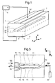
- Figure 1 shows a perspective view common to a first, a second and a third amplifiers and to a first, a second, and a third converters according to this invention.
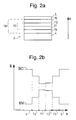
- Figures 2a, 3a and 4a respectively represent cross-sectional views of the chips semiconductors of these first, second and third amplifiers or converters according to this invention.
- Figures 2b, 3b and 4b show respectively energy level diagrams likely to be occupied by electrons at various dimensions above substrates of said chips of these amplifiers or converters, the energies of such levels being plotted on the ordinate, these dimensions being plotted on the abscissa.
- FIG. 5 represents a top view common to a fourth, a fifth and a sixth converter according to this invention.
- arrows indicate two say horizontal directions respectively constituting a longitudinal direction Z and a transverse direction Y.
- the so-called vertical direction DV has two meanings mutually opposite constituting an upward direction X and a direction down J. All of these directions are linked to a so-called semiconductor chip.
- This direct meaning is defined by the types of doping said lower and upper injection layers. It is such that this current injects charge carriers of the two so-called types in said active structure from of these injection layers.
- said active materials are included in said active structure 10 in the form of a plurality of homogeneous layers forming a succession in said vertical direction and constituting active layers, namely two such layers 11 and 12 in the case of the first object amplifier of the invention.
- This structure and these layers have respective thicknesses.
- These layers also have compositions defining respectively for these layers energy intervals, characteristic wavelengths, and gain bands, these gain bands of these layers partially overlapping each other.
- the realization of the active structure in the form of a limited number of homogeneous layers superimposed on each other has the advantage of being easier than in the form of a single thicker layer whose composition would gradually vary depending on the direction vertical.
- Each of said active layers offers amplification gains to said light waves when charge carriers of each of the two said types are present in this active layer with respective densities sufficient to allow these gains. These gains depend on the wavelengths of these waves. They are zero for the wavelengths outside the gain band of this layer.
- said gain band of the active structure is a composite gain band composed by said gain bands of said active layers. These gains also depend on the thicknesses and the positions of these layers. The thicknesses, positions and respective compositions of these active layers must then be chosen so that the same said pumping current can make appear in each of these layers and for each of the two said types of charge carriers a said density sufficient to allow a said gain for the wavelengths located in said gain band of this layer.
- said thicknesses of said active layers 11, 12 are between 20 and 400 nm, the number of these active layers is at most equal to four, and said respective energy intervals of any two of said active layers have a mutual difference at most equal to 60 meV.
- At least 80% of said core 10 of the guide of waves is constituted by said active layers.
- this core is constituted by said structure active, this means that these layers are more close to each other within this structure than quantum wells separated by barriers.
- More particularly said active layers 11, 12 are superimposed with contact between layers successive.
- Such proximity preferably ranging up to such contact, between active layers having increased refractive indices, i.e. higher to those of the surrounding layers, allows to give a high value at the confinement coefficient which represents the proportion in which the optical waves are confined to the active material. She favors thus the amplification action.
- the characteristic wavelengths of these layers containment are then external to said strip of composite gain and each of these confinement layers is in contact with a said active layer.
- All the layers of said waveguides have compositions corresponding to the formula Ga x In 1-x As y P 1-y .
- This provision is then constituted by the fact that said wavelength characteristic of said first active layer is smaller than that of said second active layer.
- Her goal is to increase the probability that the holes that are injected from the doped injection layer of the type p reach this second active layer. It is useful to achieve this goal because the probability has to be sufficient to allow said pumping current to maintain said sufficient density of these holes in this second active layer. It is reached thanks to fact that the relatively high energy interval of this first active layer gives a value relatively low the probability that these holes recombine with electrons during their course at through this first layer.
- said respective thicknesses of said active layers 11, 12 are between 50 and 200 nm approximately, said number of these active layers is at most equal to three, said difference between respective energy intervals of any two of these active layers is at most equal to 40 meV, and said pumping current has a surface intensity between 10 and 50 kA / cm2 approximately.
- At least said active layers are stressed enough to making a gain of said amplifier insensitive to a polarization of said optical waves traversing this guide.
- Such a constraint is used in known amplifiers to make the gain of an active layer insensitive to the possible polarization of optical waves propagating in this layer.
- Such insensitivity is sought in fiber optic communication networks because the waves received in a node of such a network at the outlet of a very long line most often have a polarization and because this polarization is random as to its degree and as to its direction.
- the desired stress is obtained by the choice of a suitable composition of the layer to be constrained because this choice makes it possible to give the crystalline mesh of the material of this layer a natural dimension different from that of the materials of the other layers of the semiconductor chip, this natural dimension being that which would appear in the absence of constraint.
- the crystalline continuity between the various layers of the chip then imposes on the mesh of the material of the layer to be constrained a modified dimension which is substantially equal to the natural dimension of the mesh of these other layers and this modification of dimension is accompanied by the realization of the desired constraint.
- the choice of the mesh size of a quaternary material having a chemical formula such as Ga x In 1-x As y P 1-y is compatible with the choice of the energy interval of this material despite the fact that these two choices are made through the composition of this material. This compatibility results from the presence in this formula of two parameters x and y which can be chosen independently of one another.
- the waveguide 18 of an amplifier according to this invention has a length of between 0.3 and 1 mm. This length is measured according to said longitudinal direction and it is typically equal to that of chip 2. The width of this guide is then typically between 1000 and 1500 nm.
- said active structure 10 is constituted by two layers which are a lower active layer 11 and an upper active layer 12 and which have the same thickness equal to 100 nm.
- the second and third amplifiers according to the present invention different from the first only by the constitution of their respective active structures, said confinement layers 24 and 25 of this second amplifier and 34 and 35 of this third amplifier being respectively identical to layers 14 and 15 previously described.
- This second amplifier has three layers active with the same thickness equal to 67 nm.
- That of a intermediate active layer 22 has the same composition as layer 12, a refractive index close to 3.5, and a characteristic wavelength of 1560 nm.
- Finally that of an upper active layer 23 has the same composition as layer 11, a refractive index close to 3.5 and a characteristic wavelength of 1530 nm.
- the third amplifier according to this invention also has three active layers.
- a lower active layer 31 has a thickness equal to 50 nm. Its composition is the same as that of the layer 11 and gives it a refractive index close to 3.5 and a characteristic wavelength of 1530 nm.
- An intermediate active layer 32 has a thickness equal to 100 nm. Its composition is the same as that of layer 12 and gives it a neighboring refractive index 3.5 and a characteristic wavelength of 1560 nm.
- the first, second and third said converters according to the present invention correspond first, second and third respectively amplifiers which have been described above.
- Each such converter includes a so-called semiconductor chip with said electrodes and said current source for supply this chip with its so-called pumping current, this chip not differing from the amplifier chip corresponding only by the length and width of said waveguide.
- the waveguide of such a converter presents typically a length between 1 and 4 mm and preferably between 1.5 and 2.5 mm, this length being measured in said longitudinal direction and being typically that of the chip of this converter.
- the width of this guide is typically between 1,000 and 1,500 nm.
- Such a converter performs intermodulation between the primary carrier wave and the reference wave. he may therefore be designated, to clarify the rest of the present description, by the designation "device intermodulation ".
- the fourth, fifth and sixth said converters according to this invention have such intermodulation devices. These last are identical to the first, second and third converters described above.
- the converter thus formed has the form of a Mach-Zehnder interferometer. How it works results from the fact that the secondary modulation includes a phase modulation. The latter is induced by modulation of the density of charge carriers which is caused by variations in the intensity of the wave primary carrier. It causes interference amplitude modulation of the output wave. This therefore requires balancing of respective intensities of the secondary carrier wave and of the amplified reference wave. This balancing is obtained by known means such as regulation of the intensity of the reference wave amplified by action on the pumping current of the amplifier reference. A fraction of this last wave can for that be taken out via a coupler auxiliary 95.
- Each of the converters described above comprises further an optical source 99 for supplying said wave auxiliary CW.
Abstract
Description
La présente invention concerne un composant apte à constituer notamment un amplificateur optique à semiconducteur. Un tel amplificateur comporte une structure active constituée par une couche active non dopée ou par plusieurs telles couches superposées les unes aux autres selon une direction verticale. Cette structure constitue en même temps un guide d'ondes guidant les ondes lumineuses selon une direction longitudinale. Elle est interposée entre deux couches d'injection ayant des dopages de type p et n respectivement. Un courant de pompage circule selon ladite direction verticale pour injecter des porteurs p et dans la ou les couches actives respectivement à partir de ces deux couches d'injection. La présence de ces deux types de porteurs est en effet nécessaire pour permettre à ces couches actives d'amplifier la lumière qui les parcourt grâce à des recombinaisons des porteurs d'un type avec ceux de l'autre type.The present invention relates to a component capable of constitute in particular an optical amplifier to semiconductor. Such an amplifier includes a active structure constituted by an active layer not doped or by several such superimposed layers to each other in a vertical direction. This structure at the same time constitutes a waveguide guiding light waves in one direction longitudinal. It is interposed between two layers injection systems with p and n type doping respectively. A pumping current flows according to said vertical direction for injecting carriers p and in the active layer (s) respectively from of these two injection layers. The presence of these two types of carriers is indeed necessary to allow these active layers to amplify the light that travels thanks to recombinations of carriers of a type with those of the other type.
De tels amplificateurs sont typiquement utilisés dans les noeuds des réseaux de télécommunication à fibres optiques. La capacité de transmission d'information d'un tel réseau est accrue par un multiplexage en longueur d'onde qui permet de transmettre plusieurs ondes porteuses sur une même fibre optique. Au sein d'un noeud du réseau, un même amplificateur est alors utilisé pour conférer une puissance convenable à toutes ces ondes. La capacité du réseau est d'autant plus grande que l'intervalle spectral occupé ou susceptible d'être occupé par ces ondes est large. Or l'amplificateur ne peut conférer cette puissance à ces ondes que dans la mesure où leurs longueurs d'onde sont comprises dans une bande de gain de cet amplificateur. C'est pourquoi le besoin a souvent été ressenti qu'une telle bande de gain soit élargie.Such amplifiers are typically used in the nodes of fiber telecommunications networks optical. The information transmission capacity of a such network is increased by length multiplexing wave which allows to transmit several waves carriers on the same optical fiber. Within a knot of the network, the same amplifier is then used to give a suitable power to all these waves. The network capacity is all the greater as the spectral range occupied or likely to be occupied by these waves is wide. The amplifier cannot give this power to these waves only to the extent where their wavelengths are in a band gain of this amplifier. This is why the need has often felt that such a gain band is enlarged.
Un tel élargissement a été obtenu dans un premier amplificateur connu qui est un amplificateur à guide d'ondes constituant une partie amplificatrice d'un oscillateur laser accordable. Cet oscillateur est décrit dans un document de brevet US-A-4 680 769 (Miller). Sa partie amplificatrice comporte deux dites structures actives qui sont constituées chacune par une couche active et qui se succèdent selon la direction longitudinale, c'est à dire que la lumière parcourt successivement ces deux structures et que deux courants de pompage sont fournis respectivement pour ces deux structures.Such an enlargement was obtained in a first known amplifier which is a guide amplifier of waves constituting an amplifying part of a tunable laser oscillator. This oscillator is described in US-A-4,680,769 (Miller). Her amplifier part has two so-called structures active which each consist of a layer active and successive according to the direction longitudinal, i.e. the light travels successively these two structures and that two currents pumping are provided respectively for these two structures.
L'élargissement de la bande de gain de cet amplificateur résulte du fait que les couches constituant ces deux structures actives sont constituées de deux matériaux différents. Cette différence de composition entraine une différence entre les deux intervalles énergétiques existant respectivement dans ces deux couches entre la bande de valence et la bande de conduction, ces bandes étant celles dans lesquelles se situent les niveaux d'énergie susceptibles d'être occupés par les électrons. Or ces intervalles énergétiques définissent pour le matériau actif une longueur d'onde caractéristique qui constitue une limite supérieure de la bande de gain et qui définit ainsi la position de cette bande dans le spectre des longueurs d'onde. Il en résulte que les bandes de gain des deux structures actives sont décalées l'une par rapport à l'autre. Elles se recouvrent cependant partiellement l'une l'autre. La longueur d'onde émise par l'oscillateur peut être accordée grâce au fait que, dans chacune des deux structures, les gains présentés par cette structure pour les longueurs d'onde incluses dans la bande de gain de cette structure sont commandés par le courant de pompage fourni à cette dernière. Le choix des deux courants de pompage permet alors de faire apparaítre un maximum de gain pour une longueur d'onde qui peut être choisie dans l'intervalle entre les longueurs d'onde centrales des deux bandes de gain propres aux deux structures actives.The widening of the gain band of this amplifier results from the fact that the layers constituting these two active structures consist of two different materials. This difference in composition causes a difference between the two intervals energetic respectively existing in these two layers between the valence strip and the strip of conduction, these bands being those in which locate the energy levels likely to be occupied by electrons. Now these energy intervals define for the active material a wavelength characteristic which constitutes an upper limit of the gain strip and that thus defines the position of this band in the wavelength spectrum. The result that the gain bands of the two active structures are offset from each other. They overlap however partially each other. The wavelength emitted by the oscillator can be tuned thanks to the fact that, in each of the two structures, the gains presented by this structure for wavelengths included in the gain band of this structure are controlled by the pumping current supplied to this last. The choice of the two pumping currents allows then to show a maximum gain for a wavelength which can be chosen in the interval between the central wavelengths of the two bands of gain specific to the two active structures.
S'il devait être utilisé en tant qu'amplificateur à bande de gain élargie, ce premier amplificateur connu présenterait notamment l'inconvénient de nécessiter le réglage de deux courants de pompage.If it were to be used as a booster amplifier enlarged gain band, this first known amplifier present the disadvantage of requiring the adjustment of two pumping currents.
Il est maintenant largement connu que la bande de gain d'un amplificateur à semiconducteur à guides d'ondes est plus large lorsque la structure active de cet amplificateur est constituée de puits quantiques que lorsqu'elle est constituée d'une couche active massive telle que celle de chacune des deux structures actives dudit premier amplificateur connu. Un telle couche massive est constituée d'un matériau dit en anglais "bulk material" pour "matériau massif". Les puits d'une structure à puits quantiques présentent la forme de couches actives minces qui sont superposées tout en étant séparées les unes des autres par des barrières dont les épaisseurs sont comparables à celles de ces puits. Dans le but de confiner les fonctions d'onde des porteurs de charge dans chacun de ces puits le matériau constitutif d'un tel puits est choisi pour avoir un intervalle énergétique bien inférieur à celui des barrières. La différence entre ces deux intervalles est au moins égale à 100 meV et typiquement voisine de 250 ou 300 meV. L'épaisseur de chaque tel puits est typiquement de l'ordre de 10 nm alors que celle d'une couche massive est typiquement de l'ordre de 100 nm. C'est pourquoi, pour obtenir une même épaisseur totale de matériau actif, une structure active à puits quantiques est typiquement constituée d'un nombre de puits de l'ordre de dix. La bande de gain de la structure ainsi constituée est élargie grâce au fait que la faible épaisseur de ces puits augmente la densité des niveaux énergétiques susceptibles d'être occupés par les électrons dans ces puits. Il reste cependant souhaitable d'augmenter encore la largeur de la bande de gain d'un tel amplificateur.It is now widely known that the gang of gain of a waveguide semiconductor amplifier is wider when the active structure of this amplifier consists of quantum wells that when it consists of a massive active layer such as that of each of the two active structures of said first known amplifier. Such a layer massive is made of a material called in English "bulk material "for" solid material ". The wells of a quantum well structure have the form of thin active layers which are superimposed while being separated from each other by barriers whose thicknesses are comparable to those of these wells. In the purpose of confining the wave functions of the carriers of loads the constituent material into each of these wells of such a well is chosen to have an interval energy much lower than that of barriers. The difference between these two intervals is at least equal at 100 meV and typically close to 250 or 300 meV. The thickness of each such well is typically of the order of 10 nm whereas that of a massive layer is typically of the order of 100 nm. This is why, for obtain the same total thickness of active material, a active quantum well structure is typically consisting of a number of wells of the order of ten. The gain band of the structure thus formed is enlarged thanks to the fact that the small thickness of these well increases the density of energy levels likely to be occupied by electrons in these well. However, it is desirable to further increase the width of the gain band of such an amplifier.
Un tel élargissement est réalisé dans un deuxième amplificateur connu qui est un amplificateur à semiconducteur à guide d'ondes dont la structure active est constituée de puits quantiques. Ce deuxième amplificateur connu a été décrit dans une communication du Topical Meeting on Quantum Optoelectronics, Salt Lake City, USA, March 1991, O.S.A. 1991 Tech. Digest Ser..., "Broadband GaAs/AlxGa1-xAs Multi-Quantum Well LED", A.J. Moseley, D.J. Robbins, C. Meaton, R.M. Ash, R. Nicklin, P. Bromley, R.R. Bradley, A.C. Carter, C.S. Hong and L. Figueroa. L'élargissement de sa bande de gain résulte du fait que les puits quantiques de la structure active sont constitués de matériaux actifs ayant des compositions différentes de puits à puits. Comme précédemment expliqué de telles différences de composition ont pour effet que les puits successifs ont des bandes de gain décalées les unes par rapport aux autres. Le décalage entre deux puits successifs est suffisamment petit pour que les bandes de gain respectives de ces deux puits se recouvrent partiellement, ce qui permet d'obtenir pour la structure active une bande de gain composite sensiblement continue. Cette bande peut être très large parce qu'elle inclut les bandes de gain respectives de tous les puits. Ce deuxième amplificateur connu présente notamment les inconvénients suivants :
- Sa réalisation est complexe.
- L'obtention d'un gain souhaité dans chacune des bandes de gain des diverses couches actives exige que la circulation du courant de pompage crée une densité suffisante de porteurs de charge aussi bien positifs que négatifs dans chacune de ces couches. Cette exigence est facilement satisfaite pour les porteurs de charge négatifs constitués par les électrons parce que la grande mobilité de ces derniers leur permet d'atteindre rapidement les puits quantiques les plus éloignés de la couche d'injection de type n à partir de laquelle ils ont été injectés dans la structure active. Il n'en est malheureusement pas de même pour les porteurs de charge positifs constitués par des trous dont il est bien connu que la mobilité est bien moindre. Ces trous pourraient disparaitre en trop grand nombre par recombinaison dans les puits les plus proches de la couche d'injection de type p de laquelle ils proviennent, et par suite ne pas être injectés en nombre suffisant dans les puits les plus éloignés de cette couche. Il pourrait en résulter une insuffisance ou une trop grande instabilité du gain dans les bandes de gain des couches actives les plus proches de la couche d'injection de type n. Pour éviter qu'un tel défaut d'uniformité de l'injection de trous provoque une telle insuffisance ou instabilité du gain de certains puits, tous les puits quantiques et toutes les barrières de ce deuxième laser connu reçoivent un fort dopage de type p qui augmente artificiellement en tous points la densité des trous. Ce fort dopage présente l'inconvénient de compliquer encore la réalisation de l'amplificateur et surtout d'augmenter l'absorption de la lumière dans la structure active. Or une telle perte de lumière doit être compensée par une augmentation de l'intensité du courant de pompage ce qui provoque une augmentation correspondante de la puissance thermique à évacuer.
- Its realization is complex.
- Obtaining a desired gain in each of the gain bands of the various active layers requires that the circulation of the pumping current creates a sufficient density of charge carriers, both positive and negative, in each of these layers. This requirement is easily satisfied for the negative charge carriers formed by the electrons because the great mobility of the latter allows them to quickly reach the quantum wells furthest from the n-type injection layer from which they have have been injected into the active structure. Unfortunately, this is not the same for the positive charge carriers constituted by holes of which it is well known that the mobility is much less. These holes could disappear in too large numbers by recombination in the wells closest to the p-type injection layer from which they originate, and consequently not be injected in sufficient number in the wells furthest from this layer. This could result in an insufficiency or too great instability of the gain in the gain bands of the active layers closest to the n-type injection layer. To prevent such a defect in the uniformity of the injection of holes causing such insufficiency or instability in the gain of certain wells, all the quantum wells and all the barriers of this second known laser receive a strong p-type doping which increases artificially at all points the density of the holes. This high doping has the drawback of further complicating the production of the amplifier and above all of increasing the absorption of light in the active structure. However, such a loss of light must be compensated for by an increase in the intensity of the pumping current, which causes a corresponding increase in the thermal power to be removed.
La présente invention a notamment pour but de permettre de réaliser simplement un amplificateur optique à semiconducteur ayant une bande de gain élargi et elle a notamment pour objet un tel amplificateur.The object of the present invention is in particular to allow to easily make an optical amplifier semiconductor having an enlarged gain band and it has in particular for object such an amplifier.
De même que le deuxième amplificateur connu qui a été décrit ci-avant, l'amplificateur objet de cette invention comporte un guide d'ondes faisant partie d'une puce semiconductrice constituée de couches s'étendant selon des directions horizontales de cette puce et formant une succession présentant une continuité cristalline selon une direction verticale de cette puce. Ce guide d'ondes s'étend selon une dite direction horizontale. Il inclut des matériaux actifs ayant des compositions et des intervalles énergétiques respectifs les rendant aptes à amplifier des ondes optiques se propageant dans ce guide. Ces matériaux actifs présentent selon ladite direction verticale une variation de composition entrainant une variation d'intervalle énergétique.As well as the second known amplifier which has described above, the object amplifier of this invention comprises a waveguide forming part of a semiconductor chip consisting of layers extending along horizontal directions of this chip and forming a succession with continuity crystalline in a vertical direction of this chip. This waveguide extends in a said direction horizontal. It includes active materials with compositions and respective energy intervals making them able to amplify optical waves propagating in this guide. These active materials have in said vertical direction a variation of composition causing an interval variation energetic.
L'amplificateur objet de cette invention est caractérisé par le fait que certains au moins desdits matériaux actifs sont inclus dans ledit guide d'ondes sous la forme de matériaux massifs.The amplifier object of this invention is characterized by the fact that at least some of the said active materials are included in said waveguide in the form of massive materials.
Conformément à l'usage on entend ici par matériaux massifs des matériaux qui ne forment pas des puits quantiques, c'est à dire plus précisément que ces matériaux forment au moins une couche dans l'épaisseur de laquelle ladite variation d'intervalle énergétique est au plus égale à 100 meV, cette épaisseur étant au moins égale à 20 nm et étant mesurée selon ladite direction verticale.In accordance with usage, the term “materials” is used here massive materials that do not form wells quantum, that is to say more precisely than these materials form at least one layer in the thickness of which said variation in energy interval is at more equal to 100 meV, this thickness being at least equal to 20 nm and being measured in said direction vertical.
Cette invention concerne non seulement les amplificateurs optiques mais aussi les convertisseurs de longueurs d'onde. De même que ces amplificateurs, de tels convertisseurs sont typiquement utilisés dans les noeuds de réseaux de télécommunication à fibres optiques. Lorsque, par exemple, une longueur d'onde dite ci-après primaire a été allouée à un signal pour constituer la longueur d'onde d'une onde optique portant ce signal dans une ligne joignant un premier à un deuxième noeud d'un tel réseau, un tel convertisseur est utilement inclus dans ce deuxième noeud. Il permet alors d'allouer à ce même signal une autre longueur d'onde pour constituer la longueur d'onde d'une autre onde optique portant ce signal dans une autre ligne joignant ce deuxième à un troisième noeud de ce réseau. Une telle réallocation de longueur d'onde est nécessaire dans le cas où cette autre ligne guide déjà un autre signal porté sur la longueur d'onde primaire. De tels convertisseurs peuvent aussi permettre le routage de tels signaux dans chacun des noeuds du réseau.This invention relates not only to optical amplifiers but also converters wavelengths. Like these amplifiers, such converters are typically used in nodes of fiber optic telecommunications networks. When, for example, a wavelength called below primary has been allocated to a signal to constitute the wavelength of an optical wave carrying this signal in a line joining a first to a second node of a such a network, such a converter is usefully included in this second node. It then allows to allocate to this same signal another wavelength to constitute the wavelength of another optical wave carrying this signal in another line joining this second to a third node of this network. Such a reallocation of wavelength is required in case this other line already guides another signal carried on the length primary wave. Such converters can also allow routing of such signals in each of network nodes.
Il est connu de réaliser de tels convertisseurs sous la forme de puces semiconductrices dont les structures internes sont analogues à celles de ces amplificateurs. Les contraintes techniques relatives à la réalisation de tels convertisseurs sont cependant bien différentes de celles qui concernent les amplificateurs. En particulier des amplificateurs à semiconducteurs fonctionnent typiquement dans un régime linéaire correspondant à une puissance d'entrée comprise entre -40 et -15 dBm alors qu'un tel convertisseur fonctionne dans un régime de saturation correspondant à une puissance de l'onde porteuse primaire supérieure à -15 dBm. De plus l'efficacité du convertisseur est typiquement meilleure lorsque la longueur du guide d'onde contenant son matériau actif est supérieure à 1 mm et plus particulièrement à 1,2 mm alors que la longueur optimale du guide correspondant d'un amplificateur est inférieure à 1 mm et peut être encore utilement nettement abaissée pour maintenir le régime de fonctionnement linéaire en présence de fortes puissances d'entrée.It is known to produce such converters under the form of semiconductor chips whose structures internal are analogous to those of these amplifiers. The technical constraints relating to the realization of such converters are very different from those concerning amplifiers. In particular semiconductor amplifiers work typically in a linear regime corresponding to a input power between -40 and -15 dBm then that such a converter operates in a regime of saturation corresponding to a power of the wave primary carrier greater than -15 dBm. Moreover the efficiency of the converter is typically better when the length of the waveguide containing its active material is greater than 1 mm and more particularly at 1.2 mm while the optimal length of the corresponding guide of an amplifier is less to 1 mm and can still be usefully lowered considerably to maintain the linear operating regime in presence of strong input powers.
Pour les raisons qui ont été indiquées ci-avant à propos des amplificateurs, le besoin s'est fait sentir que la bande passante optique d'un tel convertisseur soit élargie. Cette bande est la bande dans laquelle ladite longueur d'onde primaire doit se situer pour que le signal porté sur cette longueur d'onde soit l'objet d'un transfert dans ce convertisseur, ce transfert étant tel que ce signal soit porté en sortie de ce convertisseur sur une onde porteuse secondaire dont la longueur d'onde doit typiquement être située dans la même bande. Elle doit être distinguée de la bande passante de modulation qui est la bande de fréquences dans laquelle un signal doit être situé pour être l'objetdudit transfert.For the reasons which have been indicated above at about amplifiers, the need arose that the optical bandwidth of such a converter is enlarged. This band is the band in which said primary wavelength must be in order for the signal carried on this wavelength be the subject of a transfer in this converter, this transfer being such that this signal be carried at the output of this converter on a secondary carrier wave whose wavelength typically must be located in the same band. She must be distinguished from modulation bandwidth which is the frequency band in which a signal must be located to be the object of said transfer.
Un tel convertisseur de longueur d'onde optique connu a été étudié dans une thèse présentée à l'université technique du Danemark : C. J. Videcrantz, Ph. D. Thesis, Optical Amplification and Processing in High-Capacity Photonic Networks, March 1997, LD 124.Such an optical wavelength converter known was studied in a thesis presented at Technical University of Denmark: C. J. Videcrantz, Ph. D. Thesis, Optical Amplification and Processing in High-Capacity Photonic Networks, March 1997, LD 124.
Il présente notamment l'inconvénient que sa bande passante optique est rétrécie au voisinage de 30 nm lorsque son facteur de confinement présente une valeur convenable telle que 0,85.In particular, it has the disadvantage that its strip optical bandwidth is reduced to around 30 nm when its containment factor has a value suitable such as 0.85.
La présente invention a notamment pour but de permettre de réaliser simplement un convertisseur de longueur d'onde ayant une bande passante optique élargie tout en réalisant efficacement le transfert d'un signal d'une onde porteuse optique vers une autre telle onde.The object of the present invention is in particular to allow to simply make a converter wavelength having an enlarged optical bandwidth while effectively transferring a signal from one optical carrier wave to another such wave.
Et dans ce but elle a aussi pour objet un convertisseur de longueur d'onde optique. De même que le convertisseur connu mentionné ci-avant, le convertisseur objet de cette invention comporte un guide d'ondes pour guider en même temps deux ondes optiques constituant respectivement une onde porteuse primaire et une onde auxiliaire. Cette onde porteuse a une longueur d'onde dite ci-après primaire. Elle présente une modulation d'amplitude portant un signal à transmettre et constituant une modulation primaire. Ledit guide d'onde inclut une structure active sensible à ladite modulation primaire pour transformer ladite onde auxiliaire en une onde porteuse secondaire ayant une même longueur d'onde que cette onde auxiliaire tout en ayant une modulation secondaire portant ledit signal à transmettre.And for this purpose it also has for object a optical wavelength converter. As the known converter mentioned above the converter object of this invention includes a waveguide for guide two optical waves at the same time respectively a primary carrier wave and a wave auxiliary. This carrier wave has a wavelength hereinafter called primary. It has a modulation amplitude carrying a signal to be transmitted and constituting a primary modulation. Said waveguide includes an active structure sensitive to said modulation primary to transform said auxiliary wave into a secondary carrier wave having the same wavelength that this auxiliary wave while having a modulation secondary carrying said signal to be transmitted.
Le convertisseur objet de cette invention est caractérisé par le fait que ladite structure active inclut une pluralité de matériaux actifs sensibles chacun à ladite modulation primaire seulement lorsque ladite longueur d'onde primaire est comprise dans une bande spectrale constituant une bande de gain de ce matériau actif, les dites bandes de gain de ces matériaux actifs étant décalées les unes par rapport aux autres.The converter object of this invention is characterized by the fact that said active structure includes a plurality of sensitive active materials each to said primary modulation only when said primary wavelength is within a band spectral constituting a gain band of this material active, the so-called gain bands of these active materials being offset from each other.
Compte tenu du fait que, dans un tel convertisseur, la modulation de l'onde porteuse primaire agit sur l'onde auxiliaire par l'intermédiaire de la modulation d'une densité des porteurs de charges dans la structure active et compte tenu aussi du fait que cette modulation de densité de porteurs s'accompagne au moins localement d'une amplification de cette onde porteuse, une condition pour que le convertisseur soit efficace est que la longueur d'onde de cette onde porteuse soit comprise dans la bande de gain de cette structure. Le décalage qui est réalisé selon cette invention entre les bandes de gain respectives de divers matériaux actifs inclus dans cette structure élargit cette bande de gain. Il élargit donc la bande passante optique du convertisseur. Dans le cas où la modulation secondaire souhaitée en sortie de la puce semiconductrice est une modulation d'amplitude plutôt qu'une modulation de phase, cette invention permet de même d'élargir la bande de longueurs d'onde dans laquelle doit se trouver l'onde auxiliaire. Dans les réseaux de télécommunication à fibres optiques avec multiplexage en longueurs d'onde et allocations successives de longueurs d'onde en cours de routage, ces deux bandes sont typiquement identiques de sorte que l'élargissement de l'une équivaut à l'élargissement de l'autre quel que soit le type de modulation secondaire souhaité en sortie de la puce semiconductrice.Given the fact that, in such a converter, the modulation of the primary carrier wave acts on the wave auxiliary through the modulation of a density of charge carriers in the active structure and also taking into account that this modulation of density of carriers is accompanied at least locally amplification of this carrier wave, a condition for the converter to be effective is that the wavelength of this carrier wave is included in the gain band of this structure. The shift which is made according to this invention between the gain bands respective of various active materials included in this structure widens this gain band. So it expands the optical bandwidth of the converter. In the case where the desired secondary modulation at the output of the semiconductor chip is amplitude modulation rather than phase modulation, this invention allows similarly to broaden the wavelength band in which must be the auxiliary wave. In the fiber optic telecommunications networks with wavelength multiplexing and allocations successive wavelengths during routing, these two bands are typically identical so that the enlargement of one is equivalent to the enlargement of the other regardless of the type of secondary modulation desired output from the semiconductor chip.
De préférence ladite pluralité de matériaux actifs est incluse dans ladite structure active sous la forme de matériaux massifs. La mise de cette pluralité de matériaux actifs sous cette forme de matériaux massifs facilité la réalisation du convertisseur et présente l'avantage considérable de permettre d'obtenir une bonne efficacité du convertisseur. Cette efficacité est de préférence accrue par le fait par le fait que lesdits matériaux actifs constituent au moins pour partie un coeur dudit guide d'ondes en occupant au moins 80% du volume de ce coeur. Comme dans le cas de l'amplificateur de la présente invention, une telle concentration de matériau actif dans le coeur du guide d'ondes permet de donner une valeur élevée au coéfficient de confinement des ondes dans ce matériau. Dans le cas du convertisseur cette concentration permet de donner au coefficient de confinement des ondes optiques dans les zones optiquement actives une valeur aussi élevée et éventuellement plus élevée que dans le dit convertisseur connu et elle favorise ainsi l'intermodulation qui doit être réalisée entre l'onde porteuse primaire et l'onde auxiliaire.Preferably said plurality of active materials is included in said active structure in the form of massive materials. Putting this plurality of active materials in this form of massive materials facilitates the realization of the converter and presents the considerable advantage of allowing good efficiency of the converter. This efficiency is preference increased by the fact that said active materials constitute at least in part a core of said waveguide occupying at least 80% of the volume of this heart. As in the case of the amplifier of the present invention, such a concentration of active material in the heart of the waveguide allows give a high value to the confinement coefficient waves in this material. In the case of the converter this concentration makes it possible to give the coefficient of confinement of optical waves in optically zones active a value as high and possibly more high than in the known known converter and she thus promotes the intermodulation which must be carried out between the primary carrier wave and the auxiliary wave.
De préférence ladite pluralité de matériaux actifs est incluse dans ladite structure active sous la forme d'une pluralité de couches homogènes constituées respectivement par ces matériaux. Ces couches constituent respectivement des couches actives qui sont superposées les unes aux autres de préférence avec contact des unes avec les autres. Cette disposition est simple à réaliser et elle permet de donner une valeur maximale à la concentration du matériau actif dans le coeur du guide d'ondes.Preferably said plurality of active materials is included in said active structure in the form of a plurality of homogeneous layers made up respectively by these materials. These layers respectively constitute active layers which are preferably superimposed on each other with contact with each other. This provision is simple to make and it gives value maximum at the concentration of the active material in the heart of the waveguide.
A l'aide des figures schématiques ci-jointes on va décrire ci-après divers modes de mise en oeuvre de cette invention.Using the attached schematic figures we will describe below various modes of implementation of this invention.
La figure 1 représente une vue en perspective commune à un premier, un deuxième et un troisième amplificateurs et à un premier, un deuxième, et un troisième convertisseurs selon cette invention.Figure 1 shows a perspective view common to a first, a second and a third amplifiers and to a first, a second, and a third converters according to this invention.
Les figures 2a, 3a et 4a représentent respectivement des vues en coupes transversales des puces semiconductrices de ces premier, deuxième et troisième amplificateurs ou convertisseurs selon cette invention. Figures 2a, 3a and 4a respectively represent cross-sectional views of the chips semiconductors of these first, second and third amplifiers or converters according to this invention.
Les figures 2b, 3b et 4b représentent respectivement des diagrammes relatifs aux niveaux d'énergie susceptibles d'être occupés par des électrons à diverses cotes au dessus de substrats desdites puces de ces amplificateurs ou convertisseurs, les énergies de tels niveaux étant portées en ordonnées, ces cotes étant portées en abscisses.Figures 2b, 3b and 4b show respectively energy level diagrams likely to be occupied by electrons at various dimensions above substrates of said chips of these amplifiers or converters, the energies of such levels being plotted on the ordinate, these dimensions being plotted on the abscissa.
La figure 5 représente une vue de dessus commune à un quatrième, un cinquième et un sixième convertisseurs selon cette invention.FIG. 5 represents a top view common to a fourth, a fifth and a sixth converter according to this invention.
Sur ces figures des flèches indiquent deux dites directions horizontales constituant respectivement une direction longitudinale Z et une direction transversale Y. La dite direction verticale DV a deux sens mutuellement opposés constituant un sens vers le haut X et un sens vers le bas J. Toutes ces directions sont liées à une dite puce semiconductrice.In these figures arrows indicate two say horizontal directions respectively constituting a longitudinal direction Z and a transverse direction Y. The so-called vertical direction DV has two meanings mutually opposite constituting an upward direction X and a direction down J. All of these directions are linked to a so-called semiconductor chip.
En se référant aux figures 1 et 2a on va tout d'abord décrire, à propos dudit premier amplificateur selon cette invention, des dispositions préférées pour l'ensemble des amplificateurs selon cette invention. Conformément à ces figures ladite succession de couches de la puce semiconductrice 2 d'un tel amplificateur inclut notamment, de même que dans le cas desdits amplificateurs connus, les couches et ensembles de couches suivants qui se succèdent dans ledit sens vers le haut X:
- Un substrat de phosphure d'indium à dopage de type n. Un tel substrat est couramment disponible dans le commerce.
- Ladite couche d'injection inférieure. Cette couche est
constituée de phosphure d'indium. Elle a un dopage de
type n et une concentration de dopage de 3.1018 cm-3. Le
substrat et cette couche sont désignés collectivement sur
la figure par
la référence 4. - Un guide
d'ondes 18 s'étendant et guidant des ondes optiques selon la direction longitudinale Z et ayant une largeur limitée selon la direction transversale Y. Sur la figure 1la puce 2 est supposée transparente pour permettre de voir ce guide. Les diverses couches constituant ce guide sont constituées de matériaux quaternaires, c'est à dire plus spécifiquement de phosphures et arséniures d'indium et de gallium. Elles n'ont aucun dopage intentionnel. Elle seront plus précisément décrites plus loin. De même que la couche d'injection inférieure elles ont été formées par des dépôts épitaxiaux successifs sur le substrat. Une gravure a ensuite délimité le guide selon la direction transversale avant le dépôt de la couche suivante. Ce guide d'ondes inclut une structure active 10 pour amplifier lesdites ondes optiques ayant des longueurs d'onde situées dans une bande de gain de cette structure. Cette structure est apte à amplifier ces ondes lorsque ces ondes se propagent dans cette structure en présence de porteurs de charges de chacun des deux types positif et négatif. Elle a un indice de réfraction moyen supérieur à des indices de réfraction de dites couches environnant cette structure pour constituer au moins une partie d'un coeur dudit guide d'ondes. - Enfin ladite couche d'injection supérieure 5. Cette couche est constituée de phosphure d'indium. Elle a un dopage du type P et une concentration de dopage de 1018 cm-3.
- An n-doped indium phosphide substrate. Such a substrate is commonly available commercially.
- Said lower injection layer. This layer consists of indium phosphide. It has n-type doping and a doping concentration of 3.10 18 cm -3 . The substrate and this layer are collectively designated in the figure by the
reference 4. - A
waveguide 18 extending and guiding optical waves in the longitudinal direction Z and having a limited width in the transverse direction Y. In FIG. 1, thechip 2 is supposed to be transparent to allow this guide to be seen. The various layers constituting this guide are made of quaternary materials, that is to say more specifically of indium and gallium phosphides and arsenides. They have no intentional doping. They will be described more precisely below. Like the lower injection layer, they were formed by successive epitaxial deposits on the substrate. An engraving then delimited the guide in the transverse direction before the deposition of the next layer. This waveguide includes anactive structure 10 for amplifying said optical waves having wavelengths located in a gain band of this structure. This structure is capable of amplifying these waves when these waves propagate in this structure in the presence of charge carriers of each of the two positive and negative types. It has an average refractive index greater than the refractive indices of said layers surrounding this structure to constitute at least part of a core of said waveguide. - Finally, said
upper injection layer 5. This layer consists of indium phosphide. It has P-type doping and a doping concentration of 10 18 cm -3 .
Ledit amplificateur comporte en outre :
- une électrode inférieure 6 formée sur ladite puce,
- une électrode supérieure 7 formée sur cette puce et coopérant avec ladite électrode inférieure pour permettre d'injecter un courant de pompage dans cette puce selon ladite direction verticale, et
- une
source de courant 9 pour fournir ledit courant de pompage et pour l'injecter dans ladite puce dans un sens direct J constitué par l'un des deux dits sens de la direction verticale.
- a
lower electrode 6 formed on said chip, - an
upper electrode 7 formed on this chip and cooperating with said lower electrode to enable a pumping current to be injected into this chip in said vertical direction, and - a
current source 9 for supplying said pumping current and for injecting it into said chip in a direct direction J consisting of one of the two said directions of the vertical direction.
Ce sens direct est défini par les types de dopages des dites couches d'injection inférieure et supérieure. Il est tel que ce courant injecte des porteurs de charge des deux dits types dans ladite structure active à partir de ces couches d'injection.This direct meaning is defined by the types of doping said lower and upper injection layers. It is such that this current injects charge carriers of the two so-called types in said active structure from of these injection layers.
De même que dans ledit deuxième amplificateur connu ladite structure active inclut plusieurs matériaux actifs faisant apparaítre une variation de composition au sein de cette structure selon ladite direction verticale. Cette variation de composition s'accompagne de variations correspondantes affectant :
- l'intervalle énergétique local entre bande de valence et bande de conduction,
- la longueur d'onde caractéristique locale, et
- la position spectrale de la bande de gain locale.
- the local energy interval between the valence band and the conduction band,
- the local characteristic wavelength, and
- the spectral position of the local gain band.
De préférence lesdits matériaux actifs sont inclus
dans ladite structure active 10 sous la forme d'une
pluralité de couches homogènes formant une succession
selon ladite direction verticale et constituant des
couches actives, à savoir deux telles couches 11 et 12
dans le cas du premier amplificateur objet de
l'invention. Cette structure et ces couches ont des
épaisseurs respectives. Ces couches ont aussi des
compositions définissant respectivement pour ces couches
des intervalles énergétiques, des longueurs d'ondes
caractéristiques, et des bandes de gain, ces bandes de
gain de ces couches se recouvrant partiellement les unes
les autres. La réalisation de la structure active sous la
forme d'un nombre limité de couches homogènes superposées
les unes aux autres présente l'avantage d'être plus
facile que sous la forme d'une couche unique plus épaisse
dont la composition varierait graduellement selon la
direction verticale.
Chacune des dites couches actives offre des gains
d'amplification aux dites ondes lumineuses lorsque des
porteurs de charge de chacun des deux dits types sont
présents dans cette couche active avec des densités
respectives suffisantes pour permettre ces gains. Ces
gains dépendent des longueurs d'ondes de ces ondes. Ils
sont nuls pour les longueurs d'onde extérieures à la
bande de gain de cette couche. Il en résulte que ladite
bande de gain de la structure active est une bande de
gain composite composée par lesdites bandes de gain des
dites couches actives. Ces gains dépendent aussi des
épaisseurs et des positions de ces couches. Les
épaisseurs, positions et compositions respectives de ces
couches actives doivent alors être choisies pour qu'un
même dit courant de pompage puisse faire apparaítre dans
chacune de ces couches et pour chacun des deux dits types
de porteurs de charges une dite densité suffisante pour
permettre un dit gain pour les longueurs d'onde situées
dans ladite bande de gain de cette couche.Preferably said active materials are included in said
Each of said active layers offers amplification gains to said light waves when charge carriers of each of the two said types are present in this active layer with respective densities sufficient to allow these gains. These gains depend on the wavelengths of these waves. They are zero for the wavelengths outside the gain band of this layer. As a result, said gain band of the active structure is a composite gain band composed by said gain bands of said active layers. These gains also depend on the thicknesses and the positions of these layers. The thicknesses, positions and respective compositions of these active layers must then be chosen so that the same said pumping current can make appear in each of these layers and for each of the two said types of charge carriers a said density sufficient to allow a said gain for the wavelengths located in said gain band of this layer.
Certaines limitations apparaissent souhaitables pour
cela : De préférence lesdites épaisseurs des dites
couches actives 11, 12 sont comprises entre 20 et 400 nm,
le nombre de ces couches actives est au plus égal à
quatre, et lesdits intervalles énergétiques respectifs de
deux quelconques des dites couches actives présentent une
différence mutuelle au plus égale à 60 meV.Certain limitations appear desirable for
that: Preferably said thicknesses of said
Dans le cadre de la présente invention et compte tenu des matériaux semiconducteurs commercialement disponibles, il est apparu que le respect des limitations ci-dessus permettait d'obtenir économiquement une répartition suffisamment uniforme de l'injection des porteurs de charges entre les diverses couches actives pour que le gain de la structure soit à peu près uniforme dans toute la bande de gain composite. Cette uniformité d'injection était à réaliser non seulement en ce qui concerne les porteurs de charge négatifs, c'est à dire les électrons, ce qui est facile en raison de la forte mobilité de ces derniers, mais aussi en ce qui concerne les porteurs de charges positifs, c'est à dire les trous, dont la mobilité est moindre. Il n'est en particulier pas apparu nécessaire pour cela de prévoir un dopage de type p pour les couches actives.In the context of the present invention and account held semiconductor materials commercially available, it appeared that compliance with the limitations above allowed to economically obtain a sufficiently uniform distribution of the injection of charge carriers between the various active layers so that the gain of the structure is almost uniform across the composite gain band. This uniformity injection was to be carried out not only with regard to concerns negative charge carriers, i.e. electrons, which is easy due to the strong mobility of the latter, but also with regard to the carriers of positive charges, that is to say the holes, whose mobility is less. In particular it is not appeared necessary for this to provide a doping type p for active layers.
En ce qui concerne la limitation concernant la valeur maximale de la différence entre les intervalles énergétiques respectifs de deux couches actives quelconques, et compte tenu du fait que ces intervalles énergétiques définissent les longueurs d'onde caractéristiques de ces couches, il est clair qu'une telle limitation entraine une limitation de la différence correspondante entre ces longueurs d'onde caractéristiques, et donc une limitation de la largeur de la bande gain composite. Mais il doit être noté que, pour une valeur donnée de la différence maximale entre deux dits intervalles énergétiques, la différence maximale entre les longueurs d'onde caractéristiques correspondantes est d'autant plus grande que la longueur d'onde moyenne de la bande de gain composite est plus grande. Il en résulte qu'une telle limitation est peu gênante en pratique lorsque la bande de gain souhaitée est située autour de 1500 nm, ce qui est le cas dans de nombreux réseaux de télécommunication à fibres optiques.Regarding the limitation on the maximum value of the difference between the intervals respective energetic of two active layers any, and taking into account that these intervals energy define wavelengths characteristics of these layers, it is clear that a such limitation results in limitation of the difference corresponding between these wavelengths characteristics, and therefore a limitation of the width of the composite gain band. But it should be noted that for a given value of the maximum difference between two said energy intervals, the maximum difference between characteristic wavelengths the greater the length waveform of the composite gain band is more big. It follows that such a limitation is little troublesome in practice when the desired gain band is located around 1500 nm, which is the case in numerous fiber optic telecommunications networks.
De préférence au moins 80% dudit coeur 10 du guide
d'ondes est constitué par lesdites couches actives. Dans
la mesure où ce coeur est constitué par ladite structure
active, ceci revient à dire que ces couches sont plus
proches les unes des autres au sein de cette structure
que ne le seraient des puits quantiques séparés par des
barrières. Plus particulièrement lesdites couches actives
11, 12 sont superposées avec contact entre couches
successives. Une telle proximité, allant de préférence
jusqu'à un tel contact, entre des couches actives ayant
des indices de réfraction accrus, c'est à dire supérieurs
à ceux des couches environnantes, permet de donner une
valeur élevée au coefficient de confinement qui
représente la proportion dans laquelle les ondes optiques
sont confinées dans le matériau actif. Elle favorise
ainsi l'action d'amplification.Preferably at least 80% of said
De préférence ledit guide d'ondes inclut successivement selon ladite direction verticale dans ledit sens vers le haut X :
- une couche de confinement inférieure 13 ayant un indice de réfraction et une longueur d'onde caractéristique respectivement inférieures à chacun desdits indices de réfraction et à chacune des dites longueurs d'onde caractéristiques des dites couches actives,
- ladite structure active 10, et
- une couche de
confinement supérieure 14 ayant un indice de réfraction et une longueur d'onde caractéristique respectivement inférieures à chacun desdits indices de réfraction et à chacune des dites longueurs d'onde caractéristiques des dites couches actives.
- a lower confinement layer 13 having a refractive index and a characteristic wavelength respectively less than each of said refractive indices and each of said wavelengths characteristic of said active layers,
- said
active structure 10, and - an
upper confinement layer 14 having a refractive index and a characteristic wavelength respectively less than each of said refractive indices and each of said wavelengths characteristic of said active layers.
Les longueurs d'onde caractéristiques de ces couches de confinement sont alors extérieures à ladite bande de gain composite et chacune de ces couches de confinement est en contact avec une dite couche active.The characteristic wavelengths of these layers containment are then external to said strip of composite gain and each of these confinement layers is in contact with a said active layer.
La répartition des longueurs d'onde caractéristiques de diverses couches est indirectement illustrée sur les figures 2b, 3b, 4b. Sur ces figures les intervalles énergétiques des divers matériaux sont représentés par les distances verticales s'étendant entre la limite inférieure BC de la bande de conduction et la limite supérieure BV de la bande de valence. Les longueurs d'onde caractéristiques sont inversement proportionnelles à ces intervalles.The distribution of characteristic wavelengths of various layers is indirectly illustrated on the Figures 2b, 3b, 4b. In these figures the intervals energy of various materials are represented by vertical distances extending between the limit lower BC of the conduction band and the limit upper BV of the Valencia band. The lengths wave characteristics are inversely proportional at these intervals.
Toutes les couches desdits guides d'onde ont des compositions répondant à la formule GaxIn1-xAsyP1-y.All the layers of said waveguides have compositions corresponding to the formula Ga x In 1-x As y P 1-y .
Chacune desdites couches de confinement a par exemple une épaisseur égale à 100 nm. Sa composition est définie par les valeurs x= 0,2 et y = 0,44, ce qui lui donne un indice de réfraction voisin de 3,2 et une longueur d'onde caractéristique égale à 1180 nm environ.Each of said confinement layers has by example a thickness equal to 100 nm. Its composition is defined by the values x = 0.2 and y = 0.44, which gives a refractive index close to 3.2 and a characteristic wavelength equal to approximately 1180 nm.
L'insertion de telles couches de confinement entre
de telles couches d'injection et une structure active est
une disposition connue en elle même pour la réalisation
d'amplificateurs optiques à semiconducteur. Elle a pour
effet de contribuer à confiner les porteurs de charges
dans un volume qui contient la structure active. Ce
volume est celui du guide optique 18 dont un coeur est
constitué par cette structure active et dont une gaine
est constituée par les dites couches de confinement. Cet
effet est particulièrement souhaitable dans le cadre de
cette invention dans le but d'éviter que la densité de
porteurs de charge à faible mobilité devienne
insuffisante dans une couche active.The insertion of such confinement layers between
such injection layers and an active structure is
a provision known in itself for the realization
semiconductor optical amplifiers. She has for
effect of helping to contain charge carriers
in a volume that contains the active structure. This
volume is that of the
Une autre disposition est préférée dans le même but. Pour la décrire il faut considérer que ladite structure active 10 inclut successivement selon ladite direction verticale dans ledit sens direct J :
- une première dite couche active 12 et
- une deuxième dite couche active 11.
- a first so-called
active layer 12 and - a second so-called
active layer 11.
Cette disposition est alors constituée par le fait que ladite longueur d'onde caractéristique de ladite première couche active est plus petite que celle de ladite deuxième couche active. Elle a pour but d'augmenter la probabilité pour que les trous qui sont injectés à partir de la couche d'injection à dopage du type p atteignent cette deuxième couche active. Il est utile d'atteindre ce but parce que la probabilité doit être suffisante pour permettre audit courant de pompage de maintenir ladite densité suffisante de ces trous dans cette deuxième couche active. Il est atteint grâce au fait que l'intervalle énergétique relativement élevé de cette première couche active donne une valeur relativement faible à la probabilité pour que ces trous se recombinent avec des électrons pendant leur parcours à travers cette première couche.This provision is then constituted by the fact that said wavelength characteristic of said first active layer is smaller than that of said second active layer. Her goal is to increase the probability that the holes that are injected from the doped injection layer of the type p reach this second active layer. It is useful to achieve this goal because the probability has to be sufficient to allow said pumping current to maintain said sufficient density of these holes in this second active layer. It is reached thanks to fact that the relatively high energy interval of this first active layer gives a value relatively low the probability that these holes recombine with electrons during their course at through this first layer.
De préférence les dites épaisseurs respectives des
dites couches actives 11, 12 sont comprises entre 50 et
200 nm environ, ledit nombre de ces couches actives est
au plus égal à trois, ladite différence entre les
intervalles énergétiques respectifs de deux quelconques
de ces couches actives est au plus égale à 40 meV, et
ledit courant de pompage a une intensité surfaçique
comprise entre 10 et 50 kA/cm2 environ.Preferably said respective thicknesses of
said
De préférence parmi celles des dites couches qui
constituent ledit guide d'ondes 18, au moins lesdites
couches actives subissent une contrainte suffisante pour
rendre un gain dudit amplificateur insensible à une
polarisation des dites ondes optiques parcourant ce
guide.Preferably among those of said layers which
constitute said
Une telle contrainte est utilisée dans des amplificateurs connus pour rendre le gain d'une couche active insensible à la polarisation éventuelle d'ondes optiques se propageant dans cette couche. Une telle insensibilité est recherchée dans les réseaux de communication à fibres optiques parce que les ondes reçues dans un noeud d'un tel réseau en sortie d'une ligne de grande longueur présentent le plus souvent une polarisation et parce que cette polarisation est aléatoire quant à son degré et quant à sa direction. La contrainte souhaitée est obtenue par le choix d'une composition convenable de la couche à contraindre parce que ce choix permet de donner à la maille cristalline du matériau de cette couche une dimension naturelle différente de celle des matériaux des autres couches de la puce semiconductrice, cette dimension naturelle étant celle qui apparaítrait en l'absence de contrainte. La continuité cristalline entre les diverse couches de la puce impose alors à la maille du matériau de la couche à contraindre une dimension modifiée qui est sensiblement égale à la dimension naturelle de la maille de ces autres couches et cette modification de dimension s'accompagne de la réalisation de la contrainte souhaitée. Le choix de la dimension de maille d'un matériau quaternaire ayant une formule chimique telle que GaxIn1-xAsyP1-y est compatible avec le choix de l'intervalle énergétique de ce matériau malgré le fait que ces deux choix sont faits par l'intermédiaire de la composition de ce matériau. Cette compatibilité résulte de la présence dans cette formule de deux paramètres x et y pouvant être choisis indépendamment l'un de l'autre.Such a constraint is used in known amplifiers to make the gain of an active layer insensitive to the possible polarization of optical waves propagating in this layer. Such insensitivity is sought in fiber optic communication networks because the waves received in a node of such a network at the outlet of a very long line most often have a polarization and because this polarization is random as to its degree and as to its direction. The desired stress is obtained by the choice of a suitable composition of the layer to be constrained because this choice makes it possible to give the crystalline mesh of the material of this layer a natural dimension different from that of the materials of the other layers of the semiconductor chip, this natural dimension being that which would appear in the absence of constraint. The crystalline continuity between the various layers of the chip then imposes on the mesh of the material of the layer to be constrained a modified dimension which is substantially equal to the natural dimension of the mesh of these other layers and this modification of dimension is accompanied by the realization of the desired constraint. The choice of the mesh size of a quaternary material having a chemical formula such as Ga x In 1-x As y P 1-y is compatible with the choice of the energy interval of this material despite the fact that these two choices are made through the composition of this material. This compatibility results from the presence in this formula of two parameters x and y which can be chosen independently of one another.
Typiquement le guide d'ondes 18 d'un amplificateur
selon cette invention a une longueur comprise entre 0,3
et 1 mm. Cette longueur est mesurée selon ladite
direction longitudinale et elle est typiquement égale à
celle de la puce 2. La largeur de ce guide est alors
typiquement comprise entre 1 000 et 1 500 nm.Typically the
Dans le cas dudit premier amplificateur selon cette
invention ladite structure active 10 est constituée par
deux couches qui sont une couche active inférieure 11 et
une couche active supérieure 12 et qui ont une même
épaisseur égale à 100 nm.In the case of said first amplifier according to this
invention said
La composition du matériau de la couche 11 est
définie par les valeurs x = 0,44 et y = 0,89. Elle donne
à ce matériau un indice de réfraction voisin de 3,5 et
une longueur d'onde caractéristique égale à 1530 nm. De
même que pour les autres couches actives décrites ci-après
cet indice de réfraction indiqué pour la couche 11
est celui qui est vu par la lumière du composant lorsque
ledit courant de pompage circule à travers la puce.The composition of the material of
Pour la couche 12 la formule chimique est définie
par les valeurs x = 0,45 et y = 0,92. Elle donne au
matériau un indice de réfraction voisin de 3,5 et une
longueur d'onde caractéristique égale à 1560 nm.For
Les deuxième et troisième amplificateurs selon la
présente invention différent du premier seulement par la
constitution de leurs structures actives respectives,
lesdites couches de confinement 24 et 25 de ce deuxième
amplificateur et 34 et 35 de ce troisième amplificateur
étant respectivement identiques aux couches 14 et 15
précédemment décrites.The second and third amplifiers according to the
present invention different from the first only by the
constitution of their respective active structures,
said confinement layers 24 and 25 of this second
amplifier and 34 and 35 of this third amplifier
being respectively identical to
Ce deuxième amplificateur comporte trois couches
actives ayant une même épaisseur égale à 67 nm. Le
matériau d'une couche active inférieure 21 a une
composition définie par les valeurs x = 0,46 et y = 0,95.
Il a un indice de réfraction voisin de 3,5 et une
longueur d'onde caractéristique de 1590 nm. Celui d'une
couche active intermédiaire 22 a la même composition que
la couche 12, un indice de réfraction voisin de 3,5, et
une longueur d'onde caractéristique de 1560 nm. Enfin
celui d'une couche active supérieure 23 a la même
composition que la couche 11, un indice de réfraction
voisin de 3,5 et une longueur d'onde caractéristique de
1530 nm.This second amplifier has three layers
active with the same thickness equal to 67 nm. The
material of a lower
Le troisième amplificateur selon cette invention comporte lui aussi trois couches actives.The third amplifier according to this invention also has three active layers.
Une couche active inférieure 31 a une épaisseur
égale à 50 nm. Sa composition est la même que celle de la
couche 11 et lui donne un indice de réfraction voisin de
3,5 et une longueur d'onde caractéristique de 1530 nm.A lower
Une couche active intermédiaire 32 a une épaisseur
égale à 100 nm. Sa composition est la même que celle de
la couche 12 et lui donne un indice de réfraction voisin
de 3,5 et une longueur d'onde caractéristique de 1560 nm.An intermediate
Enfin une couche active supérieure 33 est identique
à la couche 31.Finally an upper active layer 33 is identical
at
Les premier, deuxième et troisième dits convertisseurs selon la présente invention correspondent respectivement aux premier, deuxième et troisième amplificateurs qui ont été décrits ci-dessus. Chaque tel convertisseur comporte une dite puce semiconductrice avec les dites électrodes et la dite source de courant pour fournir à cette puce son dit courant de pompage, cette puce ne différant de la puce de l'amplificateur correspondant que par la longueur et la largeur dudit guide d'ondes.The first, second and third said converters according to the present invention correspond first, second and third respectively amplifiers which have been described above. Each such converter includes a so-called semiconductor chip with said electrodes and said current source for supply this chip with its so-called pumping current, this chip not differing from the amplifier chip corresponding only by the length and width of said waveguide.
En se référant aux figures 1 et 5 ledit guide d'ondes 18 de ce convertisseur s'étend selon une direction longitudinale Z, entre :
- un port arrière 77 pour recevoir ladite onde auxiliaire CW sous la forme d'une onde continue dépourvue de modulation, et
un port avant 78 pour recevoir ladite onde porteuse primaire SE et pour fournir ladite onde porteuse secondaire. Cette disposition est connue en elle même et elle est dite "contradirectionnelle" parce que l'onde porteuse primaire et l'onde auxiliaire circulent dans deux sens opposés. Elle permet notamment d'allouer une même longueur d'onde à ces deux ondes lorsque cela est utile.
- a
rear port 77 for receiving said auxiliary CW wave in the form of a continuous wave without modulation, and - a
front port 78 for receiving said primary carrier wave SE and for providing said secondary carrier wave. This arrangement is known in itself and is said to be "contradirectional" because the primary carrier wave and the auxiliary wave circulate in two opposite directions. It allows in particular to allocate the same wavelength to these two waves when it is useful.
Le guide d'ondes d'un tel convertisseur présente typiquement une longueur comprise entre 1 et 4 mm et de préférence entre 1,5 et 2,5 mm, cette longueur étant mesurée selon ladite direction longitudinale et étant typiquement celle de la puce de ce convertisseur. La largeur de ce guide est typiquement comprise entre 1 000 et 1 500 nm.The waveguide of such a converter presents typically a length between 1 and 4 mm and preferably between 1.5 and 2.5 mm, this length being measured in said longitudinal direction and being typically that of the chip of this converter. The width of this guide is typically between 1,000 and 1,500 nm.
Un tel convertisseur réalise une intermodulation entre l'onde porteuse primaire et l'onde de référence. Il peut donc être désigné, pour clarifier la suite de la présente description, par l'appelation "dispositif d'intermodulation".Such a converter performs intermodulation between the primary carrier wave and the reference wave. he may therefore be designated, to clarify the rest of the present description, by the designation "device intermodulation ".
Les quatrième, cinquième et sixième dits convertisseurs selon cette invention comportent de tels dispositifs d'intermodulation. Ces derniers sont respectivement identiques aux premier, deuxième et troisième convertisseurs décrits ci-avant. The fourth, fifth and sixth said converters according to this invention have such intermodulation devices. These last are identical to the first, second and third converters described above.
Conformément à la figure 5, et dans le cas de chacun des dits quatrième, cinquième et sixième convertisseurs, le convertisseur considéré comporte une base 90 et, sur cette base :
- ledit dispositif d'intermodulation 1,
- un amplificateur de référence 91 sensiblement identique à ce dispositif d'intermodulation et constitué d'éléments ayant respectivement des mêmes fonctions et des mêmes dénominations que des éléments correspondants de ce dispositif, et
- des guides d'ondes optiques constituant :
- un coupleur en Y constituant un coupleur arrière 92 pour recevoir une onde ayant la longueur d'onde souhaitée pour ladite onde auxiliaire CW et pour transmettre deux parties égales de cette onde respectivement audit port arrière 77 dudit dispositif d'intermodulation pour constituer ladite onde auxiliaire et au port arrière 97 correspondant dudit amplificateur de référence pour constituer une onde de référence et pour que cette onde de référence soit transformée par cet amplificateur de référence en une onde de référence amplifiée, et
- un coupleur avant composite comportant :
- un coupleur en Y constituant un coupleur de sortie 93
pour recevoir la dite onde porteuse secondaire à partir
dudit
port avant 78 dudit dispositif d'intermodulation et ladite onde de référence amplifiée à partir duport avant 98 correspondant dudit amplificateur de référence et pour fournir en sortie dudit convertisseur une onde de sortie SS constituée par la réunion et par l'interférence de cette onde porteuse secondaire et de cette onde de référence amplifiée, et - un coupleur en Y constituant un coupleur d'entrée 94 pour recevoir ladite onde porteuse primaire en entrée dudit convertisseur et pour la transmettre audit port avant (78) dudit dispositif d'intermodulation.
- said
intermodulation device 1, - a
reference amplifier 91 substantially identical to this intermodulation device and consisting of elements having respectively the same functions and the same names as corresponding elements of this device, and - optical waveguides constituting:
- a Y coupler constituting a
rear coupler 92 for receiving a wave having the desired wavelength for said auxiliary wave CW and for transmitting two equal parts of this wave respectively to saidrear port 77 of said intermodulation device to constitute said auxiliary wave and to the correspondingrear port 97 of said reference amplifier to constitute a reference wave and so that this reference wave is transformed by this reference amplifier into an amplified reference wave, and - a composite front coupler comprising:
- a Y coupler constituting an
output coupler 93 for receiving said secondary carrier wave from saidfront port 78 of said intermodulation device and said reference wave amplified from the correspondingfront port 98 of said reference amplifier and for outputting of said converter an output wave SS constituted by the union and by the interference of this secondary carrier wave and this amplified reference wave, and - a Y coupler constituting an
input coupler 94 for receiving said primary carrier wave at the input of said converter and for transmitting it to said front port (78) of said intermodulation device.
Le convertisseur ainsi constitué présente la forme
d'un interféromètre de Mach-Zehnder. Son fonctionnement
résulte du fait que la modulation secondaire comporte une
modulation de phase. Cette dernière est induite par la
modulation de la densité de porteurs de charges qui est
provoquée par les variations de l'intensité de l'onde
porteuse primaire. Elle entraine par interférence une
modulation d'amplitude de l'onde de sortie. Ce
fonctionnement nécessite donc un équilibrage des
intensités respectives de l'onde porteuse secondaire et
de l'onde de référence amplifiée. Cet équilibrage est
obtenu par des moyens connus tels qu'une régulation de
l'intensité de l'onde de référence amplifiée par action
sur le courant de pompage de l'amplificateur de
référence. Une fraction de cette dernière onde peut pour
cela être prélevée par l'intermédiaire d'un coupleur
auxiliaire 95.The converter thus formed has the form
of a Mach-Zehnder interferometer. How it works
results from the fact that the secondary modulation includes a
phase modulation. The latter is induced by
modulation of the density of charge carriers which is
caused by variations in the intensity of the wave
primary carrier. It causes interference
amplitude modulation of the output wave. This
therefore requires balancing of
respective intensities of the secondary carrier wave and
of the amplified reference wave. This balancing is
obtained by known means such as regulation of
the intensity of the reference wave amplified by action
on the pumping current of the amplifier
reference. A fraction of this last wave can for
that be taken out via a
Chacun des convertisseurs décrits ci-avant comporte
en outre une source optique 99 pour fournir ladite onde
auxiliaire CW.Each of the converters described above comprises
further an
Claims (21)
ce composant étant caractérisé par le fait que certains au moins desdits matériaux actifs sont inclus dans ledit guide d'ondes sous la forme de matériaux massifs.Semiconductor optical component, this component comprising a waveguide (18) forming part of a semiconductor chip (2) consisting of layers extending in horizontal directions (Y, Z) of this chip and forming a succession having a crystal continuity in a vertical direction (X) of this chip, this waveguide extending in a said horizontal direction (Z) and including active materials (11, 12), these materials having compositions and respective energy intervals making them suitable for amplifying optical waves propagating in this guide, these materials having in said vertical direction a variation in composition causing a variation in energy interval,
this component being characterized in that at least some of said active materials are included in said waveguide in the form of solid materials.
ledit convertisseur de longueur d'onde optique étant caractérisé par le fait que ladite structure active inclut une pluralité de matériaux actifs (11, 12) sensibles chacun à ladite modulation primaire seulement lorsque ladite longueur d'onde est comprise dans une bande spectrale constituant une bande de gain de ce matériau actif, les dites bandes de gain de ces matériaux actifs étant décalées les unes par rapport aux autres. Component according to claim 1, this component constituting an optical wavelength converter, this converter comprising means for enabling said waveguide (18) to simultaneously guide two optical waves constituting respectively a primary carrier wave (SE) and an auxiliary wave (CW), this carrier wave having a primary wavelength and having an amplitude modulation carrying a signal to be transmitted and constituting a primary modulation, this wave guide including an active structure (10) sensitive to said primary modulation for transforming said auxiliary wave into a secondary carrier wave having the same wavelength as this auxiliary wave while having a secondary modulation carrying said signal to be transmitted,
said optical wavelength converter being characterized in that said active structure includes a plurality of active materials (11, 12) each sensitive to said primary modulation only when said wavelength is included in a spectral band constituting a band gain of this active material, said gain bands of these active materials being offset from each other.
Applications Claiming Priority (2)
| Application Number | Priority Date | Filing Date | Title |
|---|---|---|---|
| FR9807493A FR2779838B1 (en) | 1998-06-15 | 1998-06-15 | OPTICAL COMPONENT WITH SEMICONDUCTOR AND AMPLIFIER AND WAVELENGTH CONVERTER COMPOSED BY THIS COMPONENT |
| FR9807493 | 1998-06-15 |
Publications (1)
| Publication Number | Publication Date |
|---|---|
| EP0966078A1 true EP0966078A1 (en) | 1999-12-22 |
Family
ID=9527375
Family Applications (1)
| Application Number | Title | Priority Date | Filing Date |
|---|---|---|---|
| EP99401448A Withdrawn EP0966078A1 (en) | 1998-06-15 | 1999-06-14 | Optical semiconductor component, optical amplifier and wavelength converter comprising such a component |
Country Status (5)
| Country | Link |
|---|---|
| US (1) | US6271961B1 (en) |
| EP (1) | EP0966078A1 (en) |
| JP (1) | JP2000012984A (en) |
| CA (1) | CA2272834A1 (en) |
| FR (1) | FR2779838B1 (en) |
Families Citing this family (9)
| Publication number | Priority date | Publication date | Assignee | Title |
|---|---|---|---|---|
| JP2001053392A (en) * | 1999-06-03 | 2001-02-23 | Fujitsu Ltd | Polarization-independent type semiconductor optical amplifier |
| JP3038383B1 (en) * | 1999-06-08 | 2000-05-08 | 東京大学長 | Optical device |
| KR100301067B1 (en) * | 1999-08-23 | 2001-11-01 | 윤종용 | Method for detecting micro scratch and device adopting the same |
| US6563621B2 (en) | 2000-10-06 | 2003-05-13 | Alphion Corporation | Bit-rate and format insensitive all-optical clock extraction circuit |
| US6636318B2 (en) | 2000-10-06 | 2003-10-21 | Alphion Corp. | Bit-rate and format insensitive all-optical circuit for reshaping, regeneration and retiming of optical pulse streams |
| US20060214173A1 (en) * | 2005-03-28 | 2006-09-28 | Goldeneye, Inc. | Light emitting diodes and methods of fabrication |
| US7319555B2 (en) * | 2005-04-27 | 2008-01-15 | Alphion Corporation | Integrated performance monitoring, performance maintenance, and failure detection for photonic regenerators |
| US7319518B2 (en) * | 2005-08-24 | 2008-01-15 | Cree, Inc. | Double side polished wafer scratch inspection tool |
| JP2010121291A (en) * | 2008-11-17 | 2010-06-03 | Noda Corp | Flooring material |
Citations (5)
| Publication number | Priority date | Publication date | Assignee | Title |
|---|---|---|---|---|
| US4680769A (en) * | 1984-11-21 | 1987-07-14 | Bell Communications Research, Inc. | Broadband laser amplifier structure |
| US5283799A (en) * | 1991-02-27 | 1994-02-01 | Alcatel N.V. | Semiconductor laser with a saturable absorber |
| WO1996009668A1 (en) * | 1994-09-14 | 1996-03-28 | British Telecommunications Public Limited Company | Optical device |
| JPH08334797A (en) * | 1995-06-07 | 1996-12-17 | Oki Electric Ind Co Ltd | Optical wavelength conversion integrating element |
| US5754714A (en) * | 1994-09-17 | 1998-05-19 | Kabushiki Kaisha Toshiba | Semiconductor optical waveguide device, optical control type optical switch, and wavelength conversion device |
Family Cites Families (1)
| Publication number | Priority date | Publication date | Assignee | Title |
|---|---|---|---|---|
| JP3195159B2 (en) * | 1993-11-25 | 2001-08-06 | 株式会社東芝 | Optical semiconductor device |
-
1998
- 1998-06-15 FR FR9807493A patent/FR2779838B1/en not_active Expired - Fee Related
-
1999
- 1999-05-21 CA CA002272834A patent/CA2272834A1/en not_active Abandoned
- 1999-05-25 US US09/318,273 patent/US6271961B1/en not_active Expired - Fee Related
- 1999-06-14 EP EP99401448A patent/EP0966078A1/en not_active Withdrawn
- 1999-06-14 JP JP11167464A patent/JP2000012984A/en active Pending
Patent Citations (5)
| Publication number | Priority date | Publication date | Assignee | Title |
|---|---|---|---|---|
| US4680769A (en) * | 1984-11-21 | 1987-07-14 | Bell Communications Research, Inc. | Broadband laser amplifier structure |
| US5283799A (en) * | 1991-02-27 | 1994-02-01 | Alcatel N.V. | Semiconductor laser with a saturable absorber |
| WO1996009668A1 (en) * | 1994-09-14 | 1996-03-28 | British Telecommunications Public Limited Company | Optical device |
| US5754714A (en) * | 1994-09-17 | 1998-05-19 | Kabushiki Kaisha Toshiba | Semiconductor optical waveguide device, optical control type optical switch, and wavelength conversion device |
| JPH08334797A (en) * | 1995-06-07 | 1996-12-17 | Oki Electric Ind Co Ltd | Optical wavelength conversion integrating element |
Non-Patent Citations (1)
| Title |
|---|
| PATENT ABSTRACTS OF JAPAN vol. 097, no. 004 30 April 1997 (1997-04-30) * |
Also Published As
| Publication number | Publication date |
|---|---|
| FR2779838A1 (en) | 1999-12-17 |
| JP2000012984A (en) | 2000-01-14 |
| CA2272834A1 (en) | 1999-12-15 |
| US6271961B1 (en) | 2001-08-07 |
| FR2779838B1 (en) | 2000-08-04 |
Similar Documents
| Publication | Publication Date | Title |
|---|---|---|
| EP0742620B1 (en) | Semi-conductor lasers | |
| EP0829934B1 (en) | Method of fabricating an optoelectrical semiconductor device and a device or matrix of devices fabricated using said method | |
| EP0575227B1 (en) | Process and apparatus for the modulation and amplification of lightrays | |
| EP0527060A1 (en) | Semiconductor optical transceiver | |
| EP0667660A1 (en) | Wavelength tunable distributed Bragg reflectionlaser with a virtual diffraction grating that can be selectively operated | |
| FR2695212A1 (en) | Optical filter device | |
| FR2493616A1 (en) | HETEROSTRUCTURE INJECTION LASER | |
| FR2520158A1 (en) | INTEGRATED MULTILAYER ELECTRO-OPTICAL DEVICE | |
| EP0887668A1 (en) | Bragg reflector in a semiconductor and fabrication method | |
| EP0966078A1 (en) | Optical semiconductor component, optical amplifier and wavelength converter comprising such a component | |
| FR2695761A1 (en) | Method for manufacturing electro-optical ribbon devices, in particular lasers, and devices thus obtained. | |
| EP1138101B1 (en) | Semiconductor laser | |
| EP0752743A1 (en) | Laser device with buried structure for integrated photonic circuit and method of fabrication | |
| FR2756938A1 (en) | DEVICE, IN PARTICULAR A SEMICONDUCTOR, FOR THE TREATMENT OF TWO WAVES, IN PARTICULAR LUMINOUS | |
| EP0306400B1 (en) | Electromagnetic wave quantum well modulator and its use as polarizer | |
| EP0823982A1 (en) | Semiconductor optical amplifier | |
| EP0252565B1 (en) | Integrated semiconductor coupling device between a photodetector and a lightwave guide | |
| EP0828325A1 (en) | Optical semiconductor amplifier | |
| FR2845833A1 (en) | Clamped gain semiconductor optical amplifier having active waveguide with three dimension surround coupled laser oscillator with resonant cavities following first/second longitudinal active waveguide directions providing frequencies | |
| EP0993088A1 (en) | Semiconductor laser with tunable gain | |
| EP0992842B1 (en) | Device for regenerating a wavelength division multiplexed signal comprising a saturable absorber | |
| EP0562925B1 (en) | Semi-conductor waveguide photoreceiver with multiple quantum wells for polarisation diversity communications systems | |
| EP0664588B1 (en) | Semiconductor structure with virtual diffraction lattice | |
| EP1038342A1 (en) | Method for controlling a unipolar semiconductor laser | |
| FR2635418A1 (en) | SURFACE EMITTING LASER HAVING COMBINED LIGHT SIGNALS |
Legal Events
| Date | Code | Title | Description |
|---|---|---|---|
| PUAI | Public reference made under article 153(3) epc to a published international application that has entered the european phase |
Free format text: ORIGINAL CODE: 0009012 |
|
| AK | Designated contracting states |
Kind code of ref document: A1 Designated state(s): DE GB IT SE |
|
| AX | Request for extension of the european patent |
Free format text: AL;LT;LV;MK;RO;SI |
|
| 17P | Request for examination filed |
Effective date: 20000623 |
|
| AKX | Designation fees paid |
Free format text: DE GB IT SE |
|
| RAP1 | Party data changed (applicant data changed or rights of an application transferred) |
Owner name: AVANEX CORPORATION |
|
| RIC1 | Information provided on ipc code assigned before grant |
Ipc: 7G 02F 2/00 B Ipc: 7H 01S 5/10 A |
|
| RIC1 | Information provided on ipc code assigned before grant |
Ipc: 7G 02F 2/00 B Ipc: 7H 01S 5/10 A |
|
| GRAP | Despatch of communication of intention to grant a patent |
Free format text: ORIGINAL CODE: EPIDOSNIGR1 |
|
| STAA | Information on the status of an ep patent application or granted ep patent |
Free format text: STATUS: THE APPLICATION IS DEEMED TO BE WITHDRAWN |
|
| 18D | Application deemed to be withdrawn |
Effective date: 20050104 |