EP0966004A2 - Antriebsfeldgenerator und Energiewandler mit einem Antriebsfeldgenerator - Google Patents
Antriebsfeldgenerator und Energiewandler mit einem Antriebsfeldgenerator Download PDFInfo
- Publication number
- EP0966004A2 EP0966004A2 EP99116911A EP99116911A EP0966004A2 EP 0966004 A2 EP0966004 A2 EP 0966004A2 EP 99116911 A EP99116911 A EP 99116911A EP 99116911 A EP99116911 A EP 99116911A EP 0966004 A2 EP0966004 A2 EP 0966004A2
- Authority
- EP
- European Patent Office
- Prior art keywords
- magnetic
- magnetic field
- propulsion
- field generator
- permanent magnet
- Prior art date
- Legal status (The legal status is an assumption and is not a legal conclusion. Google has not performed a legal analysis and makes no representation as to the accuracy of the status listed.)
- Withdrawn
Links
Images



Classifications
-
- H—ELECTRICITY
- H01—ELECTRIC ELEMENTS
- H01F—MAGNETS; INDUCTANCES; TRANSFORMERS; SELECTION OF MATERIALS FOR THEIR MAGNETIC PROPERTIES
- H01F7/00—Magnets
- H01F7/06—Electromagnets; Actuators including electromagnets
- H01F7/08—Electromagnets; Actuators including electromagnets with armatures
- H01F7/16—Rectilinearly-movable armatures
- H01F7/1638—Armatures not entering the winding
- H01F7/1646—Armatures or stationary parts of magnetic circuit having permanent magnet
-
- H—ELECTRICITY
- H02—GENERATION; CONVERSION OR DISTRIBUTION OF ELECTRIC POWER
- H02K—DYNAMO-ELECTRIC MACHINES
- H02K21/00—Synchronous motors having permanent magnets; Synchronous generators having permanent magnets
- H02K21/38—Synchronous motors having permanent magnets; Synchronous generators having permanent magnets with rotating flux distributors, and armatures and magnets both stationary
- H02K21/44—Synchronous motors having permanent magnets; Synchronous generators having permanent magnets with rotating flux distributors, and armatures and magnets both stationary with armature windings wound upon the magnets
-
- H—ELECTRICITY
- H02—GENERATION; CONVERSION OR DISTRIBUTION OF ELECTRIC POWER
- H02K—DYNAMO-ELECTRIC MACHINES
- H02K33/00—Motors with reciprocating, oscillating or vibrating magnet, armature or coil system
- H02K33/02—Motors with reciprocating, oscillating or vibrating magnet, armature or coil system with armatures moved one way by energisation of a single coil system and returned by mechanical force, e.g. by springs
-
- H—ELECTRICITY
- H01—ELECTRIC ELEMENTS
- H01F—MAGNETS; INDUCTANCES; TRANSFORMERS; SELECTION OF MATERIALS FOR THEIR MAGNETIC PROPERTIES
- H01F7/00—Magnets
- H01F7/06—Electromagnets; Actuators including electromagnets
- H01F7/08—Electromagnets; Actuators including electromagnets with armatures
- H01F7/121—Guiding or setting position of armatures, e.g. retaining armatures in their end position
- H01F7/122—Guiding or setting position of armatures, e.g. retaining armatures in their end position by permanent magnets
-
- H—ELECTRICITY
- H02—GENERATION; CONVERSION OR DISTRIBUTION OF ELECTRIC POWER
- H02K—DYNAMO-ELECTRIC MACHINES
- H02K25/00—DC interrupter motors or generators
-
- H—ELECTRICITY
- H02—GENERATION; CONVERSION OR DISTRIBUTION OF ELECTRIC POWER
- H02K—DYNAMO-ELECTRIC MACHINES
- H02K37/00—Motors with rotor rotating step by step and without interrupter or commutator driven by the rotor, e.g. stepping motors
- H02K37/10—Motors with rotor rotating step by step and without interrupter or commutator driven by the rotor, e.g. stepping motors of permanent magnet type
- H02K37/20—Motors with rotor rotating step by step and without interrupter or commutator driven by the rotor, e.g. stepping motors of permanent magnet type with rotating flux distributors, the armatures and magnets both being stationary
Definitions
- the present invention relates to a propulsion magnetic field generator for generating various propulsion magnetic fields by using a permanent magnet.
- the invention furthermore, relates to an energy converter for converting magnetic field energy into kinetic energy by using this propulsion magnetic field generator, in particular to an energy converter useful when implemented es a rotary motor, a linear motor or the like.
- an exciting current is caused to flow by applying an AC voltage to an exciting coil provided in a magnetic pole of a stator with a required phase difference to generate a rotating magnetic field, and a rotor is rotated by being synchronized therewith.
- an exciting current is caused to flow by applying an AC voltage to a number of linearly arrayed exciting coils with a required phase difference, a straight advance magnetic field is generated and a propelling power is imparted to a magnetic movable body.
- a propulsion magnetic field generator used in a rotary motor, a linear motor and the like for generating a rotating magnetic field or a straight advance magnetic field has a structure designed to generate a propulsion magnetic field in a required direction by supplying an exciting current to a plurality of exciting coils with a phase difference.
- the energy cornerters of these conventional types are not structured to directly extract magnetic energy possessed by a permanent magnet to the outside and thus the energy converting efficiency thereof is relatively low.
- an energy converter such as a rotary motor, a linear motor and the like using a conventional propulsion magnetic field generator
- a rotational speed or a position moving speed is set with a phase difference of a propulsion magnetic field
- this inverter generates high frequencies and consequently damages control equipment in the vicinity thereof.
- the present invention was made in view of the above-described problems, and it is an object of the invention to provide a new propulsion magnetic field generator using a permanent magnet capable of improving energy efficiency by utilizing the magnetic attraction driving engine.
- the invention is designed to intermittently or continuously extract the required mechanical energy from a permanent magnet by using an electromagnet as a means for switching magnetic fluxes from the permanent magnet when mechanical energy is to be made by utilizing the permanent magnet.
- a propulsion magnetic field generator for generating a propulsion magnetic field in a specified working space comprises the following:
- the number of magnetic fluxes formed by the permanent magnet members in the working space is changed by shifting the phases of the magnetic fluxes by means of the magnetic flux control units.
- the magnetic flux control equipments made of the electromagnets can be structured to wind a coil on a magnetic core, set one end of the magnetic core stuck or close to one magnetic pole end of a corresponding permanent magnet, control supplying of a current to the coil and change density of magnetic fluxes formed by one magnetic pole end of the permanent magnet in a required space.
- the propulsion magnetic field generator can form rotating magnetic fields by setting the permanent magnets on a specified circumference and straight advance magnetic fields by linearly setting the permanent magnets.
- an energy converter of the invention is designed to pivotaly support a mover member freely rotatably or slidably in a working space of the propulsion magnetic filed generator and generate displacing torque in the mover member by a propulsion magnetic field formed by the propulsion magnetic field generator.
- propulsion magnetic field generator density of magnetic fluxes formed in a working space by a plurality of permanent magnets set in accordance with a predetermined pattern for generating propulsion magnetic fields is changed by magnetic flux control equipments made of electromagnets set corresponding to the permanent magnets shifting phases thereof, thereby forming predetermined propulsion magnetic fields in a working space. Therefore, if a freely rotatably supported rotor or a freely slidably supported mover such as a slider and the like is set in the working space, rotational or moving torque is generated by displacing propulsion magnetic fields formed therein.
- a propulsion magnetic flux generator of the invention utilizing a magnetic attraction driving engine has a structure designed to generate required propulsion magnetic fields such as rotating magnetic fields and the like by controlling magnetic fluxes from permanent magnets by means of magnetic flux control equipments and magnetic force energy of the permanent magnets is ulitlized, and thus a highly efficient propulsion magnetic field generator can be provided.
- FIG. 1 shows a DC type rotational motor.
- a stator side device is structured by a rotational motor 110 having a cylindrical frame 111 made of a nonmagnetic material and a revolving magnetic field generator 120 set therein.
- a working space 111A is formed so as to generate a propulsion magnetic field rotated by the revolving magnetic field generator 120 and a rotor 112 made of a soft iron nonmagnetic material is axially provided freely rotatably in the working space 111a via a rotary shaft 113.
- the rotary shaft 113 is positioned in a center axis of the frame 111, both ends thereof are freely rotatably set and prevented from moving in a direction of the rotary shaft 113 and thus the rotor 112 rotates integrally with the rotary shaft 113 inside the frame 111.
- the revolving magnetic field generator 120 is provided with six bar-shaped permanent magnets 121, 122, 123,... 126 having rectangular sections, and these permanent magnets 121, 122, 123,... 126 are set at equal spaces along an inner peripheral surface of the frame 111 with axises thereof lined up in a diameter direction of the frame 111.
- Signs 141, 142,... 146 indicate yoke members buried and fixed along an inner peripheral surface of the frame 111 as shown in the drawing and these are made of plate permalloy as a soft magnetic material.
- the yoke members 141, 142,... 146 are respectively set on positions P1, P2,... P6 of the permanent magnets 121, 122, 123,... 126 and fixed in the frame 111 (there is no limit to fixing means) so as to stick each one end of the permanent magnets 121, 122,... 126 to corresponding one of the yoke members 141, 142,... 146.
- Soft magnetic materials used for the yoke members 141, 142,... 146 are not limitted to permalloy, and other kinds can be made use of.
- N magnetic poles of the permanent magnets 121, 122 and 123 set an the positions P1, P2 and P3 are placed oppositely to the rotor 112 while S magnetic poles of the permanent magnets 124, 125 and 126 set on the positions P4, P5 and P6 are placed oppositely to the rotor 112.
- magnetic polarity of a permanent magnet set on each position can be optionally selected not limited to one in the embodiment shown in the drawing
- Signs 131, 132,... 136 indicate electromagnets as magnetic flux control means for controlling magnetic fluxes formed from the permanent magnets 121, 122,... 126 in the working Space 111A and provided corresponding to each thereof.
- the electromagnets 131, 132,... 136 are respectively composed of L-shaped magnetic cores 131A, 132A,... 136A made of soft magnetic materials such as permalloy and the like and coils 131B, 132B,... 136B wound thereon.
- Each one end of the magnetic cores 131A, 132A,... 136A is stuck to one side surface of a free end of a corresponding permanent magnet and another end thereof is stuck to that of the yoke members 141, 142,... 146, and six stator side magnetic poles M1, M2,... M6 are formed in the frame 111.
- stator side magnetic poles M2, M3,... M6 it is also possible to switch ON/OFF magnetic fluxes outputted from the permanent magnets 122, 123,... 126 to the working space 111A by performing similar control with currents supplied to the electromagnets 132, 133,... 136.
- a sign 150 indicates a control unit for controlling switching of exciting currents applied to the coils 131B, 132B,... 136B of the electromagnets 131, 132,... 136, and by switching ON/OFF magnetic fluxes from the permanent magnets for the stator side magnetic poles M1, M2,... M6 with a specified phase difference revolving magnetic fields are formed in the working space 111A.
- the control unit 150 is provided with a grounding terminal 150G and three output terminals 150A, 15OB and 150C, and three groups of exciting voltages, one including first, second and third exciting voltages A1, A2 and A3, having phases different from one another, are outputted therefrom.
- the coils 131B and 134B, the coils 132B and 135B and the coils 133B and 136B are respectively connected to each other in series.
- a first exciting current is supplied to the coils 131B and 134B, a second exciting current to the coils 132B and 135B and a third exciting current to the coils 133B and 136B.
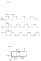
- Fig. 2 shows exciting voltages phase-controlled by the control unit 150
- first, second and third exciting voltages A1, A2 and A3 are repeating pulse voltages, each having a cycle T, by shifting a phase for a period of only 1/3 of one cycle an exciting voltage of a positive direction is supplied to any one of the phases and an exciting voltage of a negative direction is supplied to the remaining two phases.
- the second and third exciting voltages are applied with negative polarity. In this way, exciting currents are caused to flow to both electromagnets 132 and 135 so that one end of the magnetic core 132A of the electromagnet 132 is an S magnetic pole and one end of the magnetic core 135A of the electromagnet 135 is an N magnetic pole.
- exciting currents flow to both electromagnets 133 and 136 so that one end of the magnetic core 133A of the electromagnet 133 is an S magnetic pole and one end of the magnetic core 136A of the electromagnet 136 is an N magnetic pole. That is, since the stator side magnetic poles M2, M3, M5 and M6 are all in states of magnetic flux OFF, no magnetic fluxes are outputted from the permanent magnets 122, 123, 125 and 126 to the working space 111A.
- Fig. 3 is a detailed diagram showing a circuit for outputting a group of exciting voltages shown in Fig. 2.
- a sign 151 indicates a positive power source for supplying a positive voltage
- a sign 152 a negative power source for supplying a negative voltage
- signs 153, 154 and 155 switches
- a sign 156 a pulse generator for outputting a pulse CL which becomes a high level for only a period of 1/3 of a cycle T shown in Fig. 2.
- the pulse CL is supplied to the switch 153 as a first switch control signal CA, a terminal 150A is connected to the positive power source 151 when the first switch control signal CA is a high level and the terminal 150A is connected to the negative power source 152 when the first switch control signal CA is a low level.
- a first exciting voltage AI shown in Fig. 2 can be supplied from the terminal 150A.
- the pulse CL is caused to be a second switch control signal CB delayed by a first delaying circuit 157 for giving delay of only 1/3 time of the cycle T and givent to the switch 154 as a signal for switching control.
- the switch 154 is switched in accordance with a level of the second switch control signal CB and thus a second excitingiserage A2 shown in Fig. 2 can be supplied from a terminal 150B.
- a second delaying circuit 158 delays the pulse CL by a period of only 1/3 of the cycle T and outputs a third switch control signal CC shown in Fig. 4.
- the switch 155 works in response to the third switch control signal CC as in the cases of the other switches and thus a third exciting voltage A3 shown Fig. 2 can be supplied from a terminal 150C.
- switches 153, 154 and 155 shown in Fig. 3 indicate switching conditions during periods of T1 to T2 shown in Fig. 2.
- a value of a current I for excitation can be made small if the number N of winding a coil on an electromagnet is set large. This makes it possible to conserve energy serially supplied from the positive and negative power sources 151 and 152 to the electromagnet 131, 132,... 136.
- the rotational motor 110 of the invention is structured to generate revolving magnetic fields by switching ON/OFF magnetic fluxes from the permanent magnets and give rotational torque to the rotor 112 and thus it is very easy to design a space between the rotor 112 and the stator side. Since an inductive motor is a kind of trance, motor efficiency can be improved by making the space small. However, it is preferable in the rotational motor 110 of the invention that the space is designed to be sufficiently large in order to increase an initial attracting force. This consequently makes it possible to enlarge the space between the rotor 112 and the stator side in the rotational motor 110 and manufacture a motor having strong resistance to temperature increases.
- Fig. 5 shows in detail means for connecting a permanent magnet and an electromagnet in each stator side magnetic pole in the first embodiment.
- a strong separating force is applied on both magnetic core and permanent magnet in the electromagnet by a repulsive force worked thereon, and thus taking the stator side magnetic pole M1 as an example, a free end 121a of the permanent magnet 121 and an end 131a of the magnetic core 131A of the electromagnet 131 stuck thereto are firmly bound to each other by a clamping member 160 so as to surely keep both in a closely adhered state.
- Fig. 6 shows a rotational motor in another embodiment of the invention.
- a revolving magnetic field generator 180 is provided in a fixed shaft 171
- a cylindrical movable body 172 made of a magnetic material is axially provided freely rotatably so as to be coaxial with the fixed shaft 171 and magnetic projected poles 172A, 172B,... 172D are formed in the movable body 172.
- Eight stator side magnetic poles N1, N2,... N8 are set in a circumferential direction of the fixed shaft 171 at equal spaces and the magnetic projected poles 172A, 1728,... 172D are provided integrally with the movable body 172.
- a prismatic bar-shaped permanent magnet 181 like that in the first embodiment in Fig. 1 is fixed on the fixed shaft 171 so that axis thereof is orthogonal to an axis of the shaft 171 and an electromagnet 191 formed by winding a coil 191B on a U-shaped magnetic core 191A is provided as a magnetic flux controller.
- End surfaces 191C and 191D of both legs of the magnetic core 191A are stuck to N and S magnetic parts of the permanent magnet 181, and this makes it possible to secure a magnetic path between one magnetic pole and other of the permanent magnet 181 without using a yoke member.
- stator side magnetic poles N2, N3,... N8, structures are the same as the above.
- control is made to work one stator side magnetic pole as an N magnetic pole and another as an S magnetic pole with, for instance, stator side magnetic poles having spaces of 180° as one group, controls of this kind are sequentially executed in one round direction and thus revolving magnetic fields for rotating the movable body 171 can be generated.
- Fig. 8 shows still another preferred embodiment of the invention.
- an example of structuring an inductive motor by using a propulsion magnetic field generator of the invention is shown.
- a structure of an inductive motor 200 in Fig. 8 is basically the same as a rotational motor 110 shown in Fig. 1 excpet that a rotor 201 is provided in a rotary shaft 113. Therefore, the same signs are given to those corresponding to parts shown in Fig. 1 and explanation thereof is omitted.
- a revolving magnetic filed generator 220 provided in a frame 111 is structured basically in the same way as a revolving magnetic field generator 120 in the first embodiment shown in Fig. 1. However, this is different from the revolving magnetic field generator 120 in that auxilliary magnetic pole pieces 121K, 122K,... 126K are provided in free ends of permanent magnets 121, 122,... 126 for the purpose of making spaces between stator side magnetic poles M1, M2,... M6 and the rotor 201 as small as possible.
- the auxiliary magnetic pole pieces 121K, 122K,... 126K are formed as projected pole parts having opposed parts 121L, 122L,... 126L having the same curvature surfaces as those on an outer peripheral surface of the rotor 201 and from these auxiliary magnetic pole pieces 121K, 122K,... 126K magnetic fluxes from corresponding permanent magnets are outputted to a working space 111A.
- electromagnets 131, 132,... 136 of the stator side magnetic poles M1, M2,... M6 three-phase exciting voltages, i.e. first, second and third exciting voltages A1, A2 and A3, are supplied from a control unit 150 as in the case in Fig. 1 and in this way revolving magnetic fields are generated in the working space 111A.
- inductive currents are generated in the rotor 201 by these revolving magnetic fields and the rotor 201 is caused to rotate by interaction between magnetic fields generated by these inductive currents and those by the stator side magnetic poles M1, M2,... M6.
- This rotational principle is the same as one for a conventional inductive motor.
- a revolving magnetic field generator 220 generates required revolving magnetic fields in the working space 111A by utilizing magnetic force energy of the permanent magnet, it is possible to perform switching ON/OFF of magnetic fluxes by increasing the number of winding coils on the electromagnets and only by supplying small DC currents to the coils.
- an exciting current I0 of a stator iron core and a torque current I1 for making magnetic fluxes to be transmitted to rotor torque were necessary. According to the invention, however, supplying of an exciting current I0 is not necessary and thus highly efficient driving can be expected.
Landscapes
- Engineering & Computer Science (AREA)
- Power Engineering (AREA)
- Physics & Mathematics (AREA)
- Electromagnetism (AREA)
- Permanent Magnet Type Synchronous Machine (AREA)
- Linear Motors (AREA)
- Electromagnets (AREA)
Priority Applications (1)
| Application Number | Priority Date | Filing Date | Title |
|---|---|---|---|
| EP99116911A EP0966004A3 (de) | 1995-09-27 | 1995-09-27 | Antriebsfeldgenerator und Energiewandler mit einem Antriebsfeldgenerator |
Applications Claiming Priority (2)
| Application Number | Priority Date | Filing Date | Title |
|---|---|---|---|
| EP99116911A EP0966004A3 (de) | 1995-09-27 | 1995-09-27 | Antriebsfeldgenerator und Energiewandler mit einem Antriebsfeldgenerator |
| EP95115203A EP0766271B1 (de) | 1995-09-26 | 1995-09-27 | Magnetantrieb mit Permanentmagnet |
Related Parent Applications (1)
| Application Number | Title | Priority Date | Filing Date |
|---|---|---|---|
| EP95115203.2 Division | 1995-09-27 |
Publications (2)
| Publication Number | Publication Date |
|---|---|
| EP0966004A2 true EP0966004A2 (de) | 1999-12-22 |
| EP0966004A3 EP0966004A3 (de) | 2000-01-26 |
Family
ID=8219656
Family Applications (1)
| Application Number | Title | Priority Date | Filing Date |
|---|---|---|---|
| EP99116911A Withdrawn EP0966004A3 (de) | 1995-09-27 | 1995-09-27 | Antriebsfeldgenerator und Energiewandler mit einem Antriebsfeldgenerator |
Country Status (2)
| Country | Link |
|---|---|
| EP (1) | EP0966004A3 (de) |
| DE (1) | DE69519797T2 (de) |
Cited By (1)
| Publication number | Priority date | Publication date | Assignee | Title |
|---|---|---|---|---|
| WO2010117305A1 (ru) * | 2009-04-09 | 2010-10-14 | Melnichenko Andrei Anatolievich | Способ электромагнитного преобразования энергии (варианты) и устройство для его осуществления (варианты) |
Family Cites Families (4)
| Publication number | Priority date | Publication date | Assignee | Title |
|---|---|---|---|---|
| DE2707684A1 (de) * | 1977-02-23 | 1978-08-24 | Quarz Zeit Ag | Einphasenschrittmotor |
| US4542361A (en) * | 1984-05-21 | 1985-09-17 | Maghemite Inc. | Permanent magnet field diverted to do useful work |
| US4763034A (en) * | 1987-07-10 | 1988-08-09 | Sigma Instruments, Inc. | Magnetically enhanced stepping motor |
| US4983867A (en) * | 1990-06-28 | 1991-01-08 | Japan Servo Co., Ltd. | Hybrid-type stepping motor |
-
1995
- 1995-09-27 EP EP99116911A patent/EP0966004A3/de not_active Withdrawn
- 1995-09-27 DE DE1995619797 patent/DE69519797T2/de not_active Expired - Fee Related
Cited By (1)
| Publication number | Priority date | Publication date | Assignee | Title |
|---|---|---|---|---|
| WO2010117305A1 (ru) * | 2009-04-09 | 2010-10-14 | Melnichenko Andrei Anatolievich | Способ электромагнитного преобразования энергии (варианты) и устройство для его осуществления (варианты) |
Also Published As
| Publication number | Publication date |
|---|---|
| EP0966004A3 (de) | 2000-01-26 |
| DE69519797T2 (de) | 2001-05-10 |
| DE69519797D1 (de) | 2001-02-08 |
Similar Documents
| Publication | Publication Date | Title |
|---|---|---|
| US5886442A (en) | Magnetic attraction driving engine using permanent magnet | |
| US5175457A (en) | Linear motor or alternator plunger configuration using variable magnetic properties for center row and outer rows of magnets | |
| US6946938B1 (en) | Method and apparatus for coil-less magnetoelectric magnetic flux switching for permanent magnets | |
| EP0189652B1 (de) | Synchroner Wechselstrommotor | |
| US4623808A (en) | Electromechanical transducer particularly suitable for a linear alternator driven by a free-piston Stirling engine | |
| US4064442A (en) | Electric motor having permanent magnets and resonant circuit | |
| KR20080035559A (ko) | 전동기 | |
| US6051902A (en) | Magnetic attraction driving engine using permanent magnet | |
| MX2008013414A (es) | Aparato que genera electricidad utilizando una trayectoria magnetica de flujo simple. | |
| US20050156702A1 (en) | Motionless electromagnetic turbine | |
| US5606230A (en) | Direct current drive system | |
| RU2001123704A (ru) | Электрическая машина с постоянными магнитами и энергосберегающим управлением | |
| KR20030039945A (ko) | 유도전류를 이용한 회전기의 자기회로 | |
| US7205873B2 (en) | Method of and an apparatus for magnetising a plurality of adjacent portions of magnetisable material | |
| RU2098909C1 (ru) | Электромеханический привод | |
| KR100978828B1 (ko) | 분할 코일체를 갖는 회전판과 분할 자석체를 갖는 고정판에의한 전동장치 | |
| JPH09163692A (ja) | 回転界磁形永久磁石同期電動機の着磁装置 | |
| RU2366063C1 (ru) | Магнитоэлектрическая машина | |
| RU2820845C1 (ru) | Статор электрической машины постоянного тока с постоянными магнитами | |
| KR970011504B1 (ko) | 영구 자석의 반발력으로 개선된 기능을 갖는 전동기 | |
| Jabbar et al. | Permanent magnet motors for brushless operation | |
| JPH0965691A (ja) | 推進磁界発生装置及びエネルギ−変換装置 | |
| GB2205450A (en) | Rotary electro-dynamic machine | |
| JPH09182409A (ja) | 永久磁石を利用したエネルギー変換装置 | |
| WO1998024167A1 (en) | Switched reluctance electric motor |
Legal Events
| Date | Code | Title | Description |
|---|---|---|---|
| PUAI | Public reference made under article 153(3) epc to a published international application that has entered the european phase |
Free format text: ORIGINAL CODE: 0009012 |
|
| PUAL | Search report despatched |
Free format text: ORIGINAL CODE: 0009013 |
|
| 17P | Request for examination filed |
Effective date: 19990827 |
|
| AC | Divisional application: reference to earlier application |
Ref document number: 766271 Country of ref document: EP |
|
| AK | Designated contracting states |
Kind code of ref document: A2 Designated state(s): DE FR GB IT |
|
| AK | Designated contracting states |
Kind code of ref document: A3 Designated state(s): DE FR GB IT |
|
| RIC1 | Information provided on ipc code assigned before grant |
Free format text: 7H 01F 7/16 A, 7H 02K 37/04 B, 7H 02K 19/10 B, 7H 02K 33/02 B |
|
| AKX | Designation fees paid |
Free format text: DE FR GB IT |
|
| 17Q | First examination report despatched |
Effective date: 20020911 |
|
| STAA | Information on the status of an ep patent application or granted ep patent |
Free format text: STATUS: THE APPLICATION IS DEEMED TO BE WITHDRAWN |
|
| 18D | Application deemed to be withdrawn |
Effective date: 20030322 |