EP0965811B1 - Dispositif pour la suspension d'un tube horizontal d'échange de chaleur sur un tube porteur vertical - Google Patents
Dispositif pour la suspension d'un tube horizontal d'échange de chaleur sur un tube porteur vertical Download PDFInfo
- Publication number
- EP0965811B1 EP0965811B1 EP99401093A EP99401093A EP0965811B1 EP 0965811 B1 EP0965811 B1 EP 0965811B1 EP 99401093 A EP99401093 A EP 99401093A EP 99401093 A EP99401093 A EP 99401093A EP 0965811 B1 EP0965811 B1 EP 0965811B1
- Authority
- EP
- European Patent Office
- Prior art keywords
- tube
- welded
- horizontal
- receiving
- flat section
- Prior art date
- Legal status (The legal status is an assumption and is not a legal conclusion. Google has not performed a legal analysis and makes no representation as to the accuracy of the status listed.)
- Expired - Lifetime
Links
- 239000000725 suspension Substances 0.000 title description 8
- 239000002184 metal Substances 0.000 claims description 2
- 238000003466 welding Methods 0.000 description 2
Images
Classifications
-
- F—MECHANICAL ENGINEERING; LIGHTING; HEATING; WEAPONS; BLASTING
- F28—HEAT EXCHANGE IN GENERAL
- F28F—DETAILS OF HEAT-EXCHANGE AND HEAT-TRANSFER APPARATUS, OF GENERAL APPLICATION
- F28F9/00—Casings; Header boxes; Auxiliary supports for elements; Auxiliary members within casings
- F28F9/007—Auxiliary supports for elements
- F28F9/013—Auxiliary supports for elements for tubes or tube-assemblies
Definitions
- the present invention relates to a device for suspending a tube horizontal heat exchange on a vertical support tube a flat profile being welded to the vertical support tube externally to its wall and parallel to its axis, said flat profile comprising a rounded notch for receiving a support piece for receiving said horizontal tube.
- Patent FR 2 741 706 describes such a device.
- Such a device uses a molded bearing part of complex shape may crack.
- the present invention aims to provide a suspension device simpler using no complicated molded parts.
- the subject of the invention is therefore a device for suspending a tube horizontal heat exchange on a vertical support tube, a flat profile being welded to the vertical support tube outside its wall and parallel to its axis, said flat profile comprising a rounded notch for receiving a part support for receiving said horizontal tube, characterized in that said piece receiving support is a folded sheet marrying said notch and enveloping a part of the outer periphery of the tube, the upper and lower ends of which are each folded towards said flat profile to be welded therein, and in that a collar closing on the horizontal tube is fixed against said support piece reception.
- said ends folded towards the flat profile carry each cut so that these ends embrace the flat profile and be welded to it.
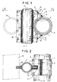
- Figure 1 shows in elevation a device according to the invention for the suspension of a horizontal heat exchange tube on a vertical support tube.
- Figure 2 is a section on II-II of Figure 1.
- Tube 1 is part of a vertical sheet of horizontal tubes such as 1 heat exchanger suspended from a few vertical support tubes such as 2 connected to a fixed structure not shown. A second layer of tubes 1A horizontal is also supported by the carrier tubes 2 facing the tubes 1. Only the suspension device for a single tube, tube 1, is shown in the drawing.
- the suspension device comprises a welded flat profile 3 outside the tube 2 parallel to its axis 4.
- This profile 3 is used for the suspension of the whole ply of tubes such as 1 (for tubes 1A, a profile 3A is also welded on the other side of the vertical tube 2).
- the profile 3 includes a rounded notch 5 for receive a receiving support piece which consists of a simple folded sheet 6 which marries by its external face the rounded notch 5 and which envelops internally part of the outer periphery of the tube 1.
- the ends 7 and 8 of the sheet 6 are folded towards the flat profile 3 and each carry a cutout 9 of so as to embrace the flat profile 3 to which each end is welded at 10.
- a collar 11 also consisting of a simple folded sheet comes close on the tube 1 and its ends 12 and 13 are welded to the folded sheet 6.
- a metal round 14 fills, when welding, the clearance between the ends of the collar 11 and the folded sheet 6.
- the shrinkage after welding wedges the tube 1 between the two half-shells formed by parts 6 and 11.
- the tube 1 is thus firmly held.
- the suspension device according to the invention is very simple and economical since it only includes laminated and notched parts.
Landscapes
- Engineering & Computer Science (AREA)
- Physics & Mathematics (AREA)
- Thermal Sciences (AREA)
- Mechanical Engineering (AREA)
- General Engineering & Computer Science (AREA)
- Heat-Exchange Devices With Radiators And Conduit Assemblies (AREA)
- Supports For Pipes And Cables (AREA)
- Details Of Heat-Exchange And Heat-Transfer (AREA)
- Driving Mechanisms And Operating Circuits Of Arc-Extinguishing High-Tension Switches (AREA)
- Measurement Of Radiation (AREA)
- Fire Alarms (AREA)
- Fire-Detection Mechanisms (AREA)
Description
Claims (3)
- Dispositif pour la suspension d'un tube horizontal (1) d'échange de chaleur sur un tube porteur vertical (2), un profilé plat (3) étant soudé au tube porteur vertical extérieurement à sa paroi et parallèlement à son axe (4), ledit profilé plat comportant une encoche arrondie (5) de réception d'une pièce support de réception dudit tube horizontal (1), caractérisé en ce que ladite pièce support de réception est une tôle pliée (6) épousant ladite encoche et enveloppant une partie du pourtour externe du tube (1), et dont les extrémités supérieure (8) et inférieure (7) sont, chacune, repliées vers ledit profilé plat (3) pour y être soudées, et en ce qu'un collier (11) venant se refermer sur le tube horizontal (1) est fixé contre ladite pièce support (6) de réception.
- Dispositif selon la revendication 1, caractérisé en ce que lesdites extrémités repliées (7, 8) vers ledit profilé plat (3) portent chacune une découpe (9) de façon à ce que ces extrémités embrassent ledit profilé plat et y soient soudées.
- Dispositif selon l'une des revendications 1 ou 2, caractérisé en ce que ledit collier (11) se refermant sur le tube horizontal (1) est soudé contre ladite pièce support de réception (6).
Applications Claiming Priority (2)
| Application Number | Priority Date | Filing Date | Title |
|---|---|---|---|
| FR9807685A FR2780151B1 (fr) | 1998-06-18 | 1998-06-18 | Dispositif pour la suspension d'un tube horizontal d'echange de chaleur sur un tube porteur vertical |
| FR9807685 | 1998-06-18 |
Publications (2)
| Publication Number | Publication Date |
|---|---|
| EP0965811A1 EP0965811A1 (fr) | 1999-12-22 |
| EP0965811B1 true EP0965811B1 (fr) | 2003-04-16 |
Family
ID=9527541
Family Applications (1)
| Application Number | Title | Priority Date | Filing Date |
|---|---|---|---|
| EP99401093A Expired - Lifetime EP0965811B1 (fr) | 1998-06-18 | 1999-05-05 | Dispositif pour la suspension d'un tube horizontal d'échange de chaleur sur un tube porteur vertical |
Country Status (10)
| Country | Link |
|---|---|
| US (1) | US6173927B1 (fr) |
| EP (1) | EP0965811B1 (fr) |
| AT (1) | ATE237790T1 (fr) |
| BR (1) | BR9902293A (fr) |
| CA (2) | CA2275220A1 (fr) |
| DE (1) | DE69906879T2 (fr) |
| ES (1) | ES2196736T3 (fr) |
| FR (1) | FR2780151B1 (fr) |
| PL (1) | PL333848A1 (fr) |
| ZA (1) | ZA994055B (fr) |
Families Citing this family (16)
| Publication number | Priority date | Publication date | Assignee | Title |
|---|---|---|---|---|
| US6929332B2 (en) * | 2002-11-27 | 2005-08-16 | Arvinmeritor Technology, Llc | Stamped ABS sensor bracket |
| AU2010213745B2 (en) * | 2009-02-12 | 2016-03-17 | Babcock Power Services Inc. | Panel support system for solar boilers |
| US8517008B2 (en) * | 2009-02-12 | 2013-08-27 | Babcock Power Services, Inc. | Modular solar receiver panels and solar boilers with modular receiver panels |
| US20110079217A1 (en) * | 2009-02-12 | 2011-04-07 | Babcock Power Services, Inc. | Piping, header, and tubing arrangements for solar boilers |
| US9163857B2 (en) * | 2009-02-12 | 2015-10-20 | Babcock Power Services, Inc. | Spray stations for temperature control in solar boilers |
| US9134043B2 (en) | 2009-02-12 | 2015-09-15 | Babcock Power Services Inc. | Heat transfer passes for solar boilers |
| US8316843B2 (en) | 2009-02-12 | 2012-11-27 | Babcock Power Services Inc. | Arrangement of tubing in solar boiler panels |
| US8397710B2 (en) * | 2009-02-12 | 2013-03-19 | Babcock Power Services Inc. | Solar receiver panels |
| US8356591B2 (en) * | 2009-02-12 | 2013-01-22 | Babcock Power Services, Inc. | Corner structure for walls of panels in solar boilers |
| US8893714B2 (en) | 2009-02-12 | 2014-11-25 | Babcock Power Services, Inc. | Expansion joints for panels in solar boilers |
| DE102010011644A1 (de) * | 2010-03-16 | 2011-09-22 | Babcock Borsig Service Gmbh | Halteelement und Spacerebene eines Rohrbündels |
| US8573196B2 (en) | 2010-08-05 | 2013-11-05 | Babcock Power Services, Inc. | Startup/shutdown systems and methods for a solar thermal power generating facility |
| JP2012081475A (ja) * | 2010-10-06 | 2012-04-26 | Mitsubishi Heavy Ind Ltd | 異材接合構造 |
| US9038624B2 (en) | 2011-06-08 | 2015-05-26 | Babcock Power Services, Inc. | Solar boiler tube panel supports |
| DE102016111336A1 (de) * | 2016-06-21 | 2017-12-21 | Tenneco Gmbh | Gehäuseverbindung |
| US20190257334A1 (en) * | 2018-02-22 | 2019-08-22 | The Babcock & Wilcox Company | Spacer tube support assembly |
Family Cites Families (14)
| Publication number | Priority date | Publication date | Assignee | Title |
|---|---|---|---|---|
| US2757649A (en) * | 1952-09-09 | 1956-08-07 | Babcock & Wilcox Co | Fluid heater with guided convection elements |
| US2923279A (en) * | 1953-09-29 | 1960-02-02 | Sulzer Ag | Pipe supporting structure for steam generators |
| DE1239319B (de) * | 1960-08-19 | 1967-04-27 | Steinmueller Gmbh L & C | Wassergekuehlte Aufhaengung von Dampferzeugern |
| US3164137A (en) * | 1962-07-05 | 1965-01-05 | Combustion Eng | Shielding of tube support for furnace tube panels |
| US3265044A (en) * | 1964-04-03 | 1966-08-09 | Combustion Eng | Heat exchanger tube support |
| US3896771A (en) * | 1974-08-01 | 1975-07-29 | Combustion Eng | Spacer and guide assembly for vertical superheater tubes |
| US4307777A (en) * | 1979-11-30 | 1981-12-29 | Combustion Engineering, Inc. | Heat exchanger tube support |
| US4512336A (en) * | 1982-10-14 | 1985-04-23 | The Babcock & Wilcox Company | Panel of vapor generating and superheating tubes |
| US4747373A (en) * | 1986-04-24 | 1988-05-31 | Westinghouse Electric Corp. | Method and apparatus for minimizing antivibration bar gaps of a steam generator |
| FR2637970B1 (fr) * | 1988-10-18 | 1990-11-23 | Stein Industrie | Dispositif de suspension de tubes horizontaux d'echange de chaleur sur un tube porteur vertical et procede de fabrication de ce dispositif |
| FR2640035B1 (fr) * | 1988-12-05 | 1991-01-11 | Stein Industrie | Dispositif de suspension d'un tube horizontal d'echange de chaleur sur un tube porteur vertical |
| US5404941A (en) * | 1993-08-10 | 1995-04-11 | The Babcock & Wilcox Company | Split ring tube spacer assembly |
| FR2741706B1 (fr) * | 1995-11-23 | 1997-12-26 | Gec Alsthom Stein Ind | Agencement de liaison de deux tubes perpendiculaires en particulier pour echangeur thermique |
| US5943985A (en) * | 1996-12-23 | 1999-08-31 | Hartman; Ernest L. | Welded bracket for supporting superheat and reheat assembly tubing on steam cooled hanger tubes |
-
1998
- 1998-06-18 FR FR9807685A patent/FR2780151B1/fr not_active Expired - Fee Related
-
1999
- 1999-05-05 EP EP99401093A patent/EP0965811B1/fr not_active Expired - Lifetime
- 1999-05-05 AT AT99401093T patent/ATE237790T1/de not_active IP Right Cessation
- 1999-05-05 ES ES99401093T patent/ES2196736T3/es not_active Expired - Lifetime
- 1999-05-05 DE DE69906879T patent/DE69906879T2/de not_active Expired - Fee Related
- 1999-06-16 CA CA002275220A patent/CA2275220A1/fr not_active Abandoned
- 1999-06-16 CA CA002275198A patent/CA2275198A1/fr not_active Abandoned
- 1999-06-17 BR BR9902293-1A patent/BR9902293A/pt not_active Application Discontinuation
- 1999-06-17 US US09/334,607 patent/US6173927B1/en not_active Expired - Fee Related
- 1999-06-18 PL PL99333848A patent/PL333848A1/xx unknown
- 1999-06-18 ZA ZA9904055A patent/ZA994055B/xx unknown
Also Published As
| Publication number | Publication date |
|---|---|
| BR9902293A (pt) | 2000-02-15 |
| EP0965811A1 (fr) | 1999-12-22 |
| DE69906879T2 (de) | 2003-12-24 |
| US6173927B1 (en) | 2001-01-16 |
| ZA994055B (en) | 2000-01-17 |
| FR2780151B1 (fr) | 2000-08-04 |
| PL333848A1 (en) | 1999-12-20 |
| CA2275198A1 (fr) | 1999-12-18 |
| ES2196736T3 (es) | 2003-12-16 |
| FR2780151A1 (fr) | 1999-12-24 |
| DE69906879D1 (de) | 2003-05-22 |
| CA2275220A1 (fr) | 1999-12-18 |
| ATE237790T1 (de) | 2003-05-15 |
Similar Documents
| Publication | Publication Date | Title |
|---|---|---|
| EP0965811A1 (fr) | Dispositif pour la suspension d'un tube horizontal d'échange de chaleur sur un tube porteur vertical | |
| EP0481871B1 (fr) | Bride pour le raccordement des tubulures d'entrée et de sortie d'un évaporateur | |
| FR2602203A3 (fr) | Raccord ameliore pour cadre de bicyclette | |
| FR2499234A1 (fr) | Echangeur de chaleur | |
| FR2917952A1 (fr) | Table de verre avec systeme de retenue permettant de fixer un plateau de table de verre a un pied de table | |
| FR2997375A1 (fr) | Cadre de bicyclette avec range-outils integre | |
| FR2654846A1 (fr) | Lunette a branches ou bandeau demontables. | |
| EP0315544B1 (fr) | Fourchette de fixation d'un barillet de serrure | |
| FR2683017A1 (fr) | Raccord pour tubes. | |
| FR2542200A1 (fr) | Support de filtre pour container, et container pour sterilisation en autoclave qui en est equipe | |
| WO2005009184A1 (fr) | Dispositif de suspension de verres a pied autour d’un seau utilisable pour le rafraichissement des boissons | |
| EP1052454B1 (fr) | Luminaire d'intérieur/industriel | |
| EP3001132B1 (fr) | Procédé de fabrication d'un échangeur de chaleur | |
| FR2920739A1 (fr) | Ensemble de carrosserie pour un vehicule et vehicule equipe d'un tel ensemble | |
| CA2418233A1 (fr) | Dispositif de commande d'aube a angle de calage variable a liaison sans jeu | |
| FR2518192A1 (fr) | Dispositif d'assemblage de deux pieces, telles que deux profiles realises par exemple en alliage leger | |
| FR2732454A1 (fr) | Echangeur de chaleur, notamment pour vehicule automobile | |
| FR2548758A1 (fr) | Bouteille transportable pour gaz liquefie sous pression | |
| EP0780655A1 (fr) | Echangeur de chaleur à boîte à fluide brasée, en particulier pour véhicule automobile | |
| EP3400858B1 (fr) | Dispositif de fixation d' accessoires a un radiateur | |
| FR2719982A1 (fr) | Table à piètement amovible. | |
| EP0775885B1 (fr) | Agencement de liaison de deux tubes perpendiculaires en particulier pour échangeur thermique | |
| WO2004065881A1 (fr) | Echangeur de chaleur muni d'un reservoir, en particulier pour vehicule automobile, et procede pour sa fabrication | |
| FR2738540A1 (fr) | Pare-chocs pour chariot et chariot equipe d'un tel pare-chocs | |
| FR2712064A1 (fr) | Dispositif à colonne de mise en place d'objets dans un espace sous plafond. |
Legal Events
| Date | Code | Title | Description |
|---|---|---|---|
| PUAI | Public reference made under article 153(3) epc to a published international application that has entered the european phase |
Free format text: ORIGINAL CODE: 0009012 |
|
| AK | Designated contracting states |
Kind code of ref document: A1 Designated state(s): AT BE DE DK ES FI GB GR IE IT LU NL SE |
|
| AX | Request for extension of the european patent |
Free format text: AL;LT;LV;MK;RO;SI |
|
| 17P | Request for examination filed |
Effective date: 20000623 |
|
| AKX | Designation fees paid |
Free format text: AT BE DE DK ES FI GB GR IE IT LU NL SE |
|
| GRAH | Despatch of communication of intention to grant a patent |
Free format text: ORIGINAL CODE: EPIDOS IGRA |
|
| GRAH | Despatch of communication of intention to grant a patent |
Free format text: ORIGINAL CODE: EPIDOS IGRA |
|
| GRAA | (expected) grant |
Free format text: ORIGINAL CODE: 0009210 |
|
| AK | Designated contracting states |
Designated state(s): AT BE DE DK ES FI GB GR IE IT LU NL SE |
|
| PG25 | Lapsed in a contracting state [announced via postgrant information from national office to epo] |
Ref country code: NL Free format text: LAPSE BECAUSE OF FAILURE TO SUBMIT A TRANSLATION OF THE DESCRIPTION OR TO PAY THE FEE WITHIN THE PRESCRIBED TIME-LIMIT Effective date: 20030416 Ref country code: IT Free format text: LAPSE BECAUSE OF FAILURE TO SUBMIT A TRANSLATION OF THE DESCRIPTION OR TO PAY THE FEE WITHIN THE PRESCRIBED TIME-LIMIT;WARNING: LAPSES OF ITALIAN PATENTS WITH EFFECTIVE DATE BEFORE 2007 MAY HAVE OCCURRED AT ANY TIME BEFORE 2007. THE CORRECT EFFECTIVE DATE MAY BE DIFFERENT FROM THE ONE RECORDED. Effective date: 20030416 Ref country code: IE Free format text: LAPSE BECAUSE OF NON-PAYMENT OF DUE FEES Effective date: 20030416 Ref country code: FI Free format text: LAPSE BECAUSE OF FAILURE TO SUBMIT A TRANSLATION OF THE DESCRIPTION OR TO PAY THE FEE WITHIN THE PRESCRIBED TIME-LIMIT Effective date: 20030416 Ref country code: AT Free format text: LAPSE BECAUSE OF FAILURE TO SUBMIT A TRANSLATION OF THE DESCRIPTION OR TO PAY THE FEE WITHIN THE PRESCRIBED TIME-LIMIT Effective date: 20030416 |
|
| REG | Reference to a national code |
Ref country code: GB Ref legal event code: FG4D Free format text: NOT ENGLISH |
|
| PG25 | Lapsed in a contracting state [announced via postgrant information from national office to epo] |
Ref country code: LU Free format text: LAPSE BECAUSE OF NON-PAYMENT OF DUE FEES Effective date: 20030505 |
|
| REF | Corresponds to: |
Ref document number: 69906879 Country of ref document: DE Date of ref document: 20030522 Kind code of ref document: P |
|
| REG | Reference to a national code |
Ref country code: IE Ref legal event code: FG4D Free format text: FRENCH |
|
| PG25 | Lapsed in a contracting state [announced via postgrant information from national office to epo] |
Ref country code: BE Free format text: LAPSE BECAUSE OF NON-PAYMENT OF DUE FEES Effective date: 20030531 |
|
| GBT | Gb: translation of ep patent filed (gb section 77(6)(a)/1977) | ||
| PG25 | Lapsed in a contracting state [announced via postgrant information from national office to epo] |
Ref country code: SE Free format text: LAPSE BECAUSE OF FAILURE TO SUBMIT A TRANSLATION OF THE DESCRIPTION OR TO PAY THE FEE WITHIN THE PRESCRIBED TIME-LIMIT Effective date: 20030716 Ref country code: GR Free format text: LAPSE BECAUSE OF FAILURE TO SUBMIT A TRANSLATION OF THE DESCRIPTION OR TO PAY THE FEE WITHIN THE PRESCRIBED TIME-LIMIT Effective date: 20030716 Ref country code: DK Free format text: LAPSE BECAUSE OF FAILURE TO SUBMIT A TRANSLATION OF THE DESCRIPTION OR TO PAY THE FEE WITHIN THE PRESCRIBED TIME-LIMIT Effective date: 20030716 |
|
| NLV1 | Nl: lapsed or annulled due to failure to fulfill the requirements of art. 29p and 29m of the patents act | ||
| REG | Reference to a national code |
Ref country code: IE Ref legal event code: FD4D Ref document number: 0965811E Country of ref document: IE |
|
| BERE | Be: lapsed |
Owner name: S.A. *ALSTOM FRANCE Effective date: 20030531 |
|
| REG | Reference to a national code |
Ref country code: ES Ref legal event code: FG2A Ref document number: 2196736 Country of ref document: ES Kind code of ref document: T3 |
|
| PLBE | No opposition filed within time limit |
Free format text: ORIGINAL CODE: 0009261 |
|
| STAA | Information on the status of an ep patent application or granted ep patent |
Free format text: STATUS: NO OPPOSITION FILED WITHIN TIME LIMIT |
|
| 26N | No opposition filed |
Effective date: 20040119 |
|
| PGFP | Annual fee paid to national office [announced via postgrant information from national office to epo] |
Ref country code: ES Payment date: 20060621 Year of fee payment: 8 |
|
| PGFP | Annual fee paid to national office [announced via postgrant information from national office to epo] |
Ref country code: DE Payment date: 20070404 Year of fee payment: 9 |
|
| PGFP | Annual fee paid to national office [announced via postgrant information from national office to epo] |
Ref country code: GB Payment date: 20070413 Year of fee payment: 9 |
|
| REG | Reference to a national code |
Ref country code: ES Ref legal event code: FD2A Effective date: 20070507 |
|
| PG25 | Lapsed in a contracting state [announced via postgrant information from national office to epo] |
Ref country code: ES Free format text: LAPSE BECAUSE OF NON-PAYMENT OF DUE FEES Effective date: 20070507 |
|
| GBPC | Gb: european patent ceased through non-payment of renewal fee |
Effective date: 20080505 |
|
| PG25 | Lapsed in a contracting state [announced via postgrant information from national office to epo] |
Ref country code: DE Free format text: LAPSE BECAUSE OF NON-PAYMENT OF DUE FEES Effective date: 20081202 |
|
| PG25 | Lapsed in a contracting state [announced via postgrant information from national office to epo] |
Ref country code: GB Free format text: LAPSE BECAUSE OF NON-PAYMENT OF DUE FEES Effective date: 20080505 |