EP0965806A2 - Method and apparatus for drying a textile fabric - Google Patents
Method and apparatus for drying a textile fabric Download PDFInfo
- Publication number
- EP0965806A2 EP0965806A2 EP99304683A EP99304683A EP0965806A2 EP 0965806 A2 EP0965806 A2 EP 0965806A2 EP 99304683 A EP99304683 A EP 99304683A EP 99304683 A EP99304683 A EP 99304683A EP 0965806 A2 EP0965806 A2 EP 0965806A2
- Authority
- EP
- European Patent Office
- Prior art keywords
- fabric
- drying
- emitters
- temperature
- emitter
- Prior art date
- Legal status (The legal status is an assumption and is not a legal conclusion. Google has not performed a legal analysis and makes no representation as to the accuracy of the status listed.)
- Withdrawn
Links
- 239000004744 fabric Substances 0.000 title claims abstract description 139
- 238000001035 drying Methods 0.000 title claims abstract description 52
- 239000004753 textile Substances 0.000 title claims description 25
- 238000000034 method Methods 0.000 title claims description 9
- 238000009998 heat setting Methods 0.000 claims description 23
- 238000012544 monitoring process Methods 0.000 claims description 9
- 238000001704 evaporation Methods 0.000 abstract description 2
- 238000005259 measurement Methods 0.000 description 5
- 239000000835 fiber Substances 0.000 description 3
- 230000005855 radiation Effects 0.000 description 3
- 238000002485 combustion reaction Methods 0.000 description 1
- 238000010981 drying operation Methods 0.000 description 1
- 230000008020 evaporation Effects 0.000 description 1
- 238000007603 infrared drying Methods 0.000 description 1
- 230000000149 penetrating effect Effects 0.000 description 1
- XLYOFNOQVPJJNP-UHFFFAOYSA-N water Substances O XLYOFNOQVPJJNP-UHFFFAOYSA-N 0.000 description 1
Images

Classifications
-
- F—MECHANICAL ENGINEERING; LIGHTING; HEATING; WEAPONS; BLASTING
- F26—DRYING
- F26B—DRYING SOLID MATERIALS OR OBJECTS BY REMOVING LIQUID THEREFROM
- F26B13/00—Machines and apparatus for drying fabrics, fibres, yarns, or other materials in long lengths, with progressive movement
- F26B13/10—Arrangements for feeding, heating or supporting materials; Controlling movement, tension or position of materials
- F26B13/12—Controlling movement, tension or position of material
-
- F—MECHANICAL ENGINEERING; LIGHTING; HEATING; WEAPONS; BLASTING
- F26—DRYING
- F26B—DRYING SOLID MATERIALS OR OBJECTS BY REMOVING LIQUID THEREFROM
- F26B3/00—Drying solid materials or objects by processes involving the application of heat
- F26B3/28—Drying solid materials or objects by processes involving the application of heat by radiation, e.g. from the sun
- F26B3/30—Drying solid materials or objects by processes involving the application of heat by radiation, e.g. from the sun from infrared-emitting elements
-
- F—MECHANICAL ENGINEERING; LIGHTING; HEATING; WEAPONS; BLASTING
- F26—DRYING
- F26B—DRYING SOLID MATERIALS OR OBJECTS BY REMOVING LIQUID THEREFROM
- F26B3/00—Drying solid materials or objects by processes involving the application of heat
- F26B3/28—Drying solid materials or objects by processes involving the application of heat by radiation, e.g. from the sun
- F26B3/30—Drying solid materials or objects by processes involving the application of heat by radiation, e.g. from the sun from infrared-emitting elements
- F26B3/305—Drying solid materials or objects by processes involving the application of heat by radiation, e.g. from the sun from infrared-emitting elements the infrared radiation being generated by combustion or combustion gases
Definitions
- the present invention relates to a method and apparatus for drying a textile fabric.
- infra red energy for textile drying is well known.
- gas-fired and electric infra red emitters have been used to part-dry textile fabrics.
- Such dryers operate at high temperatures and require careful control since there is a constant risk of scorching or burning the fabric that is being dried.
- infra red dryers have traditionally been supplemented by conventional hot air dryers which operate at much lower temperatures so that the fabric is only partially dried by the infra red dryers before the fabric is then fully dried by the hot air dryers.
- Hot air dyers are controlled by monitoring the surface temperature and/or the moisture content of the fabric being dried.
- moisture measurement systems When drying using infra red energy it has been found that the surface temperature of different fabrics varied by up to 30°C for a given residual moisture content.
- Existing moisture measurement systems cannot accurately measure the moisture content of different fabrics without being preprogrammed with information relating to fibre content. Consequently in order to obtain meaningful information from the measurements it is necessary to know the exact fibre type and content of the fabric to be dried as it enters the drying machine. In cases of mixed fabrics the precise fibre content is often not known making accurate moisture measurement impossible.
- current infra red drying apparatus it is not possible to dry different fabrics entering the machine continuously one after the other to a desired residual moisture content without the risk of scorching or burning them.
- a method for drying a textile fabric comprising the steps of:
- the above method allows the drying of fabrics of different types in sequence to the desired residual moisture content without risk of burning or scorching, and without knowing the fabric composition.
- the frequency of emission of the gas emitter is preferably between 2.7 and 3.2 microns.
- apparatus for drying a textile fabric comprising a conveyor for conveying the fabric through a drying zone to dry the fabric to a desired residual moisture content, a plurality of gas fired infra red emitters spaced along the drying zone, at least one temperature transducer disposed after one or more of the emitters and for measuring the surface temperature of the fabric, means for monitoring the speed of the conveyor, a diffused laser for measuring the amount of steam given off by the fabric in the drying zone, a controller for calculating the heat energy required to achieve the desired residual moisture content and for selectively switching each emitter on or off and/or varying the speed of the conveyor in order to ensure the calculated heat energy is imparted to the fabric by the emitters.
- the diffused laser comprises a transmitter at one end of the drying zone and a receiver at the other, the laser beam being configured to pass above the surface of the fabric.
- the surface temperature transducer is preferably a pyrometer that is shielded from direct radiation from the emitters. Alternatively it may be a compensated pyrometer.
- a method of drying and heat setting a textile fabric comprising the steps of:
- apparatus for drying and heat setting a textile fabric comprising: a conveyor for conveying the textile fabric through a drying zone and a heat setting zone, the drying zone comprising a succession of spaced gas fired infra-red emitters to dry the fabric and raise it to a first predetermined temperature and means for measuring the surface temperature of the fabric after one or more of the gas fired infra red emitters, the heat setting zone comprising at least one modulated electric short wave infra red emitter to raise the temperature of the fabric and means for measuring the surface temperature of the fabric after it passes the short wave emitter; means for monitoring the speed at which the fabric is conveyed, a controller for calculating the heat energy required to achieve the first predetermined temperature of the fabric, for selectively switching each emitter on or off and/or varying the speed of the conveyor in order to ensure the calculated heat energy is imparted to the fabric, and for modulating the short wave emitter to ensure the temperature of the fabric is at a second predetermined value at an exit of the
- the means for measuring the surface temperature is preferably a shielded or compensated pyrometer.
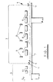
- the textile fabric 1 to be dried is conveyed between parallel endless stenter chains 2.
- the fabric 1 is gripped along each side edge by clips or pins (not shown) provided on the chain 2 so that it is conveyed through a drying zone 3 from entry to exit areas 4,5.
- each gas emitter 6 typically has a running temperature of 850°C and heats up or cools down rapidly after being switched on or off.
- a commercially available emitter is supplied by Stordy Combustion Engineering Limited. Such an emitter cools from the running temperature within two seconds and heats up from switch on to approaching running temperature within four seconds and to full running temperature within 10 seconds.
- the emitters 6 direct the infra red rays downwards toward the conveyed fabric 1 which overlies an infra red reflective board 7 that is disposed under the area enclosed by the stenter chain 2.
- the gas emitters 6 are interspersed by non-contact infra red pyrometers 8 that are positioned on alternate sides of the gas emitters 6 along the length of the drying zone 3. Each pyrometer 8 is screened from the radiation of the emitters 6 to prevent inaccurate temperature readings. Alternatively a compensated pyrometer is used which is programmed with information relating to the type and location of the emitters and other information so that stray readings are not considered.
- a heat setting zone 9 Downstream of the drying zone 3 there is a heat setting zone 9 in which there are two short wave electric infra red emitters 10 positioned one after the other above the conveyed fabric 1, followed immediately by a compensated infra red pyrometer 11.
- the heat setting zone raises the temperature of the fabric 1 to a desired value after it has been dried in the drying zone 3.
- a diffused laser beam is transmitted just above the surface of the fabric from a laser transmitter 12 in the entry area to a laser receiver 13 in the exit area of the drying zone.
- the pyrometer temperature readings are transmitted to a central controller that incorporates a processor and which controls the operation of the emitters and the speed of the stenter chains (and therefore the speed of passage of the fabric through the drying and heat setting zones).
- the frequency of the gas fired emitters is tuned to between 2.7 and 3.2 microns which is the most efficient frequency for the evaporation of water.
- the controller does not modulate the emitter frequency but simply switches the individual emitters on or off as desired.
- the electric emitters heat set the fabric to a temperature of typically 180°C. Electric short wave emitters are more efficient in penetrating the fabric to raise its temperature evenly to the required temperature once all the moisture has been evaporated and can be modulated efficiently.
- the surface temperature of the fabric is measured by the respective pyrometer and the reading is passed to the controller.
- the absolute temperature measured by the pyrometer is not used to control the drying operation as different fabrics will have different temperatures at each stage but the pyrometers will immediately identify a change in temperature due to a different fabric.
- a rapid rise or fall in the reading of the first pyrometer in the dying zone will alert the controller to a change in fabric and if this is confirmed by the reading of the next pyrometer the controller switches on or off the last emitter or last few emitters depending on the magnitude of change in the pyrometer readings.
- This arrangement provides for an "early warning" and prevents dramatic final temperature variations. The risk of the fabric emerging from the drying zone in a scorched, burned or over-damp state is therefore reduced significantly.
- the controller which adjusts the speed of the stenter chain conveyor to give the required residual moisture content.
- the controller calculates the optimal number of switched on emitters that are required to dry the particular fabric to the desired residual moisture at the maximum speed of the conveyor and switches on the emitters accordingly.
- the apparatus of the present invention thus balances the energy emitted with that required by the fabric so that the fabric is not over-dried. This is in contrast to a conventional hot air dryer where the fabric can be subjected to any amount of excess energy without damage and therefore can often be over-dried.
- the diffused laser beam is not used.
- the gas emitters are simply used to raise the temperature of the fabric towards the required heat setting temperature, for example to 160°C.
- the dried fabric leaves the drying zone and then enters the heat set zone where it passes under the short wave electric emitters which bring the temperature of the fabric up to the required heat setting temperature (e.g. 180°C).
- the compensated infra red pyrometer readings are fed to the controller which modulates the output of the emitters to maintain the fabric temperature at the required heat setting value.
- the heat-setting zone is used optionally. To dry a fabric to a predetermined residual moisture content the fabric is only heated in the drying zone.
Landscapes
- Engineering & Computer Science (AREA)
- Chemical & Material Sciences (AREA)
- Combustion & Propulsion (AREA)
- Mechanical Engineering (AREA)
- General Engineering & Computer Science (AREA)
- Life Sciences & Earth Sciences (AREA)
- Microbiology (AREA)
- Textile Engineering (AREA)
- Drying Of Solid Materials (AREA)
Abstract
Description
Claims (11)
- A method for drying a textile fabric comprising the steps of:a) conveying the textile fabric through a drying zone comprising a succession of spaced gas fired infra-red emitters to dry the fabric to a desired residual moisture content;b) measuring the surface temperature of the fabric after one or more of the emitters;c) monitoring the speed at which the fabric is conveyed;d) measuring the amount of steam given off by the fabric in the drying zone;e) calculating from the values treasured in b), c) and d) the heat energy required to achieve the desired residual moisture content of the fabric;f) selectively switching each emitter on or off and/or varying the speed of conveyance of the fabric in order to ensure the calculated heat energy is imparted to the fabric;
- Apparatus for drying a textile fabric comprising a conveyor for conveying the fabric through a drying zone to dry the fabric to a desired residual moisture content, a plurality of gas fired infra red emitters spaced along the drying zone, at least one temperature transducer disposed after one or more of the emitters and for measuring the surface temperature of the fabric, means for monitoring the speed of the conveyor, a diffused laser for measuring the amount of steam given off by the fabric in the drying zone, a controller for calculating the heat energy required to achieve the desired residual moisture content and for selectively switching each emitter on or off and/or varying the speed of the conveyor in order to ensure the calculated heat energy is imparted to the fabric by the emitters.
- Apparatus according to claim 2, wherein the diffused laser comprises a transmitter at one end of the drying zone and a receiver at the other, the laser beam being configured to pass between the two above the surface of the fabric.
- Apparatus according to claim 2 or 3, wherein the surface temperature transducer is a pyrometer that is shielded from direct emission from the emitters or is compensated.
- A method of drying and heat setting a textile fabric comprising the steps of:a) conveying the textile fabric through a drying zone comprising a succession of spaced gas fired infra-red emitters to dry the fabric and raise it to a first predetermined temperature;b) measuring the surface temperature of the fabric after one or more of the emitters;c) monitoring the speed at which the fabric is conveyed;d) calculating the heat energy required to achieve the first predetermined temperature of the fabric;e) selectively switching each emitter on or off and/or varying the speed of conveyance of the fabric in order to ensure the calculated heat energy is imparted to the fabric;f) conveying the fabric through a heat setting zone comprising at least one modulated electric short wave infra red emitter to raise the temperature of the fabric; andg) measuring the surface temperature of the fabric after it passes the short wave emitter and modulating the short wave emitter to ensure the temperature of the fabric is at a second predetermined value at an exit of the heat setting zone.
- Apparatus for drying and heat setting a textile fabric comprising: a conveyor for conveying the textile fabric through a drying zone and a heat setting zone, the drying zone comprising a succession of spaced gas fired infra-red emitters to dry the fabric and raise it to a first predetermined temperature and means for measuring the surface temperature of the fabric after one or more of the gas fired infra red emitters, the heat setting zone comprising at least one modulated electric short wave infra red emitter to raise the temperature of the fabric and means for measuring the surface temperature of the fabric after it passes the short wave emitter; means for monitoring the speed at which the fabric is conveyed, a controller for calculating the heat energy required to achieve the first predetermined temperature of the fabric, for selectively switching each emitter on or off and/or varying the speed of the conveyor in order to ensure the calculated heat energy is imparted to the fabric, and for modulating the short wave emitter to ensure the temperature of the fabric is at a second predetermined value at an exit of the heat setting zone.
- Apparatus according to claim 6, wherein the means for measuring the surface temperature is a shielded or compensated pyrometer.
- A method for drying a textile fabric substantially as hereinbefore described with reference to the accompanying drawings.
- Apparatus for drying a textile fabric substantially as hereinbefore described with reference to the accompanying drawings.
- A method for drying and heat setting a textile fabric substantially as hereinbefore described with reference to the accompanying drawings.
- Apparatus for drying and heat setting as textile fabric substantially as hereinbefore described with reference to the accompanying drawings.
Applications Claiming Priority (2)
| Application Number | Priority Date | Filing Date | Title |
|---|---|---|---|
| GB9812947 | 1998-06-17 | ||
| GBGB9812947.1A GB9812947D0 (en) | 1998-06-17 | 1998-06-17 | Method and apparatus for drying a textile fabric |
Publications (2)
| Publication Number | Publication Date |
|---|---|
| EP0965806A2 true EP0965806A2 (en) | 1999-12-22 |
| EP0965806A3 EP0965806A3 (en) | 2001-05-09 |
Family
ID=10833836
Family Applications (1)
| Application Number | Title | Priority Date | Filing Date |
|---|---|---|---|
| EP99304683A Withdrawn EP0965806A3 (en) | 1998-06-17 | 1999-06-16 | Method and apparatus for drying a textile fabric |
Country Status (2)
| Country | Link |
|---|---|
| EP (1) | EP0965806A3 (en) |
| GB (1) | GB9812947D0 (en) |
Cited By (7)
| Publication number | Priority date | Publication date | Assignee | Title |
|---|---|---|---|---|
| WO2003029546A1 (en) * | 2001-09-28 | 2003-04-10 | Devendra Somabhai Naik | A stenter machine |
| CN102321925A (en) * | 2011-08-09 | 2012-01-18 | 浙江理工大学 | Infrared drying control device for rereeled raw-silks and special application method thereof |
| EP2418316A1 (en) * | 2010-08-11 | 2012-02-15 | BurnusHychem GmbH | Method for drying with infrared radiation and device for executing the method |
| US9238887B2 (en) | 2010-07-23 | 2016-01-19 | Mabe, S.A. De C.V. | Drying method and profile |
| CN109654873A (en) * | 2018-12-29 | 2019-04-19 | 上海兰宝传感科技股份有限公司 | Method for controlling water content |
| CN115035503A (en) * | 2022-06-01 | 2022-09-09 | 浙江衣拿智能科技股份有限公司 | Control method and device of drying and carrying system and electronic equipment |
| CN115200344A (en) * | 2022-07-25 | 2022-10-18 | 德意佳机械江苏有限公司 | Built-in evaporation drying device of top fan of airflow dyeing machine |
Family Cites Families (7)
| Publication number | Priority date | Publication date | Assignee | Title |
|---|---|---|---|---|
| US3078587A (en) * | 1959-01-29 | 1963-02-26 | William F Huck | Coordinated heater and speed control for web drying machines |
| US3254422A (en) * | 1962-07-10 | 1966-06-07 | Du Pont | Process of drying polychloroprene sheets |
| US3406954A (en) * | 1966-07-06 | 1968-10-22 | Fostoria Fannon Inc | Apparatus for web drying |
| NL8001944A (en) * | 1980-04-02 | 1981-11-02 | Vries Jacob De | DEVICE FOR HEATING A SHEET OR PATH MATERIAL. |
| US4498864A (en) * | 1982-12-10 | 1985-02-12 | Techmark Corporation | Method and apparatus for uniformly drying moving webs |
| DE3438859A1 (en) * | 1983-12-30 | 1985-07-11 | VEB Forschung und Entwicklung Betrieb des VEB Kombinat Wolle und Seide, DDR 6600 Greiz | METHOD AND ARRANGEMENT FOR OPTIMIZING THERMAL TREATMENT PROCESSES OF SURFACES |
| DE3710202A1 (en) * | 1987-03-27 | 1988-10-06 | Brueckner Trockentechnik Gmbh | Regulating method for operating a tentering machine for heat treatment of textile fabric webs |
-
1998
- 1998-06-17 GB GBGB9812947.1A patent/GB9812947D0/en not_active Ceased
-
1999
- 1999-06-16 EP EP99304683A patent/EP0965806A3/en not_active Withdrawn
Cited By (7)
| Publication number | Priority date | Publication date | Assignee | Title |
|---|---|---|---|---|
| WO2003029546A1 (en) * | 2001-09-28 | 2003-04-10 | Devendra Somabhai Naik | A stenter machine |
| US9238887B2 (en) | 2010-07-23 | 2016-01-19 | Mabe, S.A. De C.V. | Drying method and profile |
| EP2418316A1 (en) * | 2010-08-11 | 2012-02-15 | BurnusHychem GmbH | Method for drying with infrared radiation and device for executing the method |
| CN102321925A (en) * | 2011-08-09 | 2012-01-18 | 浙江理工大学 | Infrared drying control device for rereeled raw-silks and special application method thereof |
| CN109654873A (en) * | 2018-12-29 | 2019-04-19 | 上海兰宝传感科技股份有限公司 | Method for controlling water content |
| CN115035503A (en) * | 2022-06-01 | 2022-09-09 | 浙江衣拿智能科技股份有限公司 | Control method and device of drying and carrying system and electronic equipment |
| CN115200344A (en) * | 2022-07-25 | 2022-10-18 | 德意佳机械江苏有限公司 | Built-in evaporation drying device of top fan of airflow dyeing machine |
Also Published As
| Publication number | Publication date |
|---|---|
| GB9812947D0 (en) | 1998-08-12 |
| EP0965806A3 (en) | 2001-05-09 |
Similar Documents
| Publication | Publication Date | Title |
|---|---|---|
| CA1108722A (en) | Process for the uniform dyeing of textile material webs with the aid of a uniform pre-drying | |
| US5625962A (en) | Method for measuring the moisture content of a web of goods on a through-flow dryer and device for working the method | |
| FI95841B (en) | Moisture sensor for paper web and method for controlling moisture in a paper web | |
| CA1267926A (en) | Multi stage heater | |
| US7494567B2 (en) | Combined paper sheet temperature and moisture sensor | |
| US11156401B2 (en) | System and method for dynamically adjusting dryer belt speed | |
| CA1318785C (en) | Method and apparatus for drying wet particulate material to a predetermined uniform moisture content | |
| US4498248A (en) | Method and device for controlling a continuous heat treatment of a textile fabric web | |
| EP0892331A3 (en) | Apparatus for setting heating condition in heating furnace and thermal analyzer for object to be heated in heating furnace | |
| US4614044A (en) | Method and apparatus for optimizing thermal treatment processes for fabrics | |
| GB1591819A (en) | Method and apparatus fro drying burley or green leaf tobacco | |
| US5323546A (en) | Method of drying photographic materials | |
| EP0458825A1 (en) | Drying. | |
| US4413427A (en) | Fuel control system for dryer | |
| US3758960A (en) | Apparatus for drying materials | |
| US6974035B2 (en) | Method and system for producing a moisture content map for use in moisture sorting green veneer using light transmission | |
| US4656756A (en) | Method for heat-treating textile material and tenter for carrying out method | |
| US3395459A (en) | Temperature-sensitive speed-adjustable conveyor-type dryer | |
| US6393729B1 (en) | Method, control paradigm and means for monitoring and controlling the process variables of a process gas flowing through a dryer hood used in a drying process | |
| KR940703996A (en) | Method for adjusting heating of object in heating chamber and system (System For The Controlled Heating Of An Object) | |
| FI84658B (en) | FOERFARANDE OCH ANLAEGGNING FOER TORKNING AV ETT SKIVFORMIGT MATERIAL, TILL EXEMPEL ENKELT FANER. | |
| JP2572182B2 (en) | Far infrared heating device | |
| NL1001633C2 (en) | Device for detecting color variation in moving colored material webs. | |
| GB2078938A (en) | Measurement of moisture content | |
| EP0259413A1 (en) | Method of and apparatus for measuring and controlling the humidity of drying air in a textile material drying machine |
Legal Events
| Date | Code | Title | Description |
|---|---|---|---|
| PUAI | Public reference made under article 153(3) epc to a published international application that has entered the european phase |
Free format text: ORIGINAL CODE: 0009012 |
|
| AK | Designated contracting states |
Kind code of ref document: A2 Designated state(s): AT BE CH CY DE DK ES FI FR GB GR IE IT LI LU MC NL PT SE |
|
| AX | Request for extension of the european patent |
Free format text: AL;LT;LV;MK;RO;SI |
|
| PUAL | Search report despatched |
Free format text: ORIGINAL CODE: 0009013 |
|
| AK | Designated contracting states |
Kind code of ref document: A3 Designated state(s): AT BE CH CY DE DK ES FI FR GB GR IE IT LI LU MC NL PT SE |
|
| AX | Request for extension of the european patent |
Free format text: AL;LT;LV;MK;RO;SI |
|
| AKX | Designation fees paid | ||
| REG | Reference to a national code |
Ref country code: DE Ref legal event code: 8566 |
|
| STAA | Information on the status of an ep patent application or granted ep patent |
Free format text: STATUS: THE APPLICATION IS DEEMED TO BE WITHDRAWN |
|
| 18D | Application deemed to be withdrawn |
Effective date: 20011110 |