EP0965366B1 - Golf putter - Google Patents
Golf putter Download PDFInfo
- Publication number
- EP0965366B1 EP0965366B1 EP99304704A EP99304704A EP0965366B1 EP 0965366 B1 EP0965366 B1 EP 0965366B1 EP 99304704 A EP99304704 A EP 99304704A EP 99304704 A EP99304704 A EP 99304704A EP 0965366 B1 EP0965366 B1 EP 0965366B1
- Authority
- EP
- European Patent Office
- Prior art keywords
- golf club
- inner insert
- outer shell
- cavity
- shaft
- Prior art date
- Legal status (The legal status is an assumption and is not a legal conclusion. Google has not performed a legal analysis and makes no representation as to the accuracy of the status listed.)
- Expired - Lifetime
Links
- 235000009508 confectionery Nutrition 0.000 claims description 6
- 239000000463 material Substances 0.000 claims description 6
- 239000011800 void material Substances 0.000 claims description 6
- 229910000906 Bronze Inorganic materials 0.000 claims description 3
- 239000010974 bronze Substances 0.000 claims description 3
- KUNSUQLRTQLHQQ-UHFFFAOYSA-N copper tin Chemical compound [Cu].[Sn] KUNSUQLRTQLHQQ-UHFFFAOYSA-N 0.000 claims description 3
- XAGFODPZIPBFFR-UHFFFAOYSA-N aluminium Chemical compound [Al] XAGFODPZIPBFFR-UHFFFAOYSA-N 0.000 claims description 2
- 229910052782 aluminium Inorganic materials 0.000 claims description 2
- 229920001084 poly(chloroprene) Polymers 0.000 claims description 2
- 230000005540 biological transmission Effects 0.000 description 2
- 230000000694 effects Effects 0.000 description 2
- OKTJSMMVPCPJKN-UHFFFAOYSA-N Carbon Chemical compound [C] OKTJSMMVPCPJKN-UHFFFAOYSA-N 0.000 description 1
- 239000004411 aluminium Substances 0.000 description 1
- 229910052799 carbon Inorganic materials 0.000 description 1
- 238000005553 drilling Methods 0.000 description 1
- 239000000835 fiber Substances 0.000 description 1
- 238000004519 manufacturing process Methods 0.000 description 1
- 230000035939 shock Effects 0.000 description 1
- 230000003019 stabilising effect Effects 0.000 description 1
Images
Classifications
-
- A—HUMAN NECESSITIES
- A63—SPORTS; GAMES; AMUSEMENTS
- A63B—APPARATUS FOR PHYSICAL TRAINING, GYMNASTICS, SWIMMING, CLIMBING, OR FENCING; BALL GAMES; TRAINING EQUIPMENT
- A63B53/00—Golf clubs
- A63B53/04—Heads
- A63B53/0487—Heads for putters
-
- A—HUMAN NECESSITIES
- A63—SPORTS; GAMES; AMUSEMENTS
- A63B—APPARATUS FOR PHYSICAL TRAINING, GYMNASTICS, SWIMMING, CLIMBING, OR FENCING; BALL GAMES; TRAINING EQUIPMENT
- A63B53/00—Golf clubs
- A63B53/02—Joint structures between the head and the shaft
-
- A—HUMAN NECESSITIES
- A63—SPORTS; GAMES; AMUSEMENTS
- A63B—APPARATUS FOR PHYSICAL TRAINING, GYMNASTICS, SWIMMING, CLIMBING, OR FENCING; BALL GAMES; TRAINING EQUIPMENT
- A63B53/00—Golf clubs
- A63B53/04—Heads
-
- A—HUMAN NECESSITIES
- A63—SPORTS; GAMES; AMUSEMENTS
- A63B—APPARATUS FOR PHYSICAL TRAINING, GYMNASTICS, SWIMMING, CLIMBING, OR FENCING; BALL GAMES; TRAINING EQUIPMENT
- A63B53/00—Golf clubs
- A63B53/04—Heads
- A63B53/0416—Heads having an impact surface provided by a face insert
-
- A—HUMAN NECESSITIES
- A63—SPORTS; GAMES; AMUSEMENTS
- A63B—APPARATUS FOR PHYSICAL TRAINING, GYMNASTICS, SWIMMING, CLIMBING, OR FENCING; BALL GAMES; TRAINING EQUIPMENT
- A63B53/00—Golf clubs
- A63B53/04—Heads
- A63B53/0441—Heads with visual indicators for aligning the golf club
-
- A—HUMAN NECESSITIES
- A63—SPORTS; GAMES; AMUSEMENTS
- A63B—APPARATUS FOR PHYSICAL TRAINING, GYMNASTICS, SWIMMING, CLIMBING, OR FENCING; BALL GAMES; TRAINING EQUIPMENT
- A63B53/00—Golf clubs
- A63B53/10—Non-metallic shafts
-
- A—HUMAN NECESSITIES
- A63—SPORTS; GAMES; AMUSEMENTS
- A63B—APPARATUS FOR PHYSICAL TRAINING, GYMNASTICS, SWIMMING, CLIMBING, OR FENCING; BALL GAMES; TRAINING EQUIPMENT
- A63B60/00—Details or accessories of golf clubs, bats, rackets or the like
- A63B60/02—Ballast means for adjusting the centre of mass
-
- A—HUMAN NECESSITIES
- A63—SPORTS; GAMES; AMUSEMENTS
- A63B—APPARATUS FOR PHYSICAL TRAINING, GYMNASTICS, SWIMMING, CLIMBING, OR FENCING; BALL GAMES; TRAINING EQUIPMENT
- A63B53/00—Golf clubs
- A63B53/04—Heads
- A63B2053/0491—Heads with added weights, e.g. changeable, replaceable
-
- A—HUMAN NECESSITIES
- A63—SPORTS; GAMES; AMUSEMENTS
- A63B—APPARATUS FOR PHYSICAL TRAINING, GYMNASTICS, SWIMMING, CLIMBING, OR FENCING; BALL GAMES; TRAINING EQUIPMENT
- A63B60/00—Details or accessories of golf clubs, bats, rackets or the like
- A63B60/52—Details or accessories of golf clubs, bats, rackets or the like with slits
Definitions
- a golf club 1 comprises a head 2 connected to a shaft 3.
- the head 2 has a striking face 4 with a so called sweet- spot 5 which is usually arranged to occur at the geometrical centre of area of the striking face 4 as indicated by the crossed lines.
- impact with a golf ball is sought to take place at the sweet-spot 5.
- a problem with this prior art arrangement is that the shaft 3 is displaced somewhat from the impact area and is fixed directly to the head 2. As a consequence of this some of the energy of impact is dissipated within the head thus lessening the amount of impact energy which can be transmitted up the shaft to the player's hands so that in one sense the amount of energy available to define "feel" is reduced.
- US5,090,698 describes a golf putter in which the sweet spot is effectively extended over much of the striking surface.
- the striking face forms part of the golf club head itself and therefore a significant proportion of the impact energy is dissipated within the head with the disadvantageous effects described above.
- US4,411,430 discloses a golf putter having an eccentrically weighted portion inside the golf club head which may be rotated to shift the axial centre of mass of the head. This enables the golfer to correct manufacturing variations and to correct errors in the putting stroke.
- the striking surface of the putter effectively forms an integral part of the golf club head and similarly can result in reduced "feel" sensed by the player.
- a golf club having a head including a striking face with a sweet spot, the head comprising an outer shell member defining a cavity, an inner insert member located within the cavity spaced from the outer shell member and defining the sweet spot, and a shaft connection fixed to the inner insert member through the outer shell member, characterized in that the inner insert member is resiliently supported and resiliently fixed within the cavity such that a clearance space exists between the inner insert member and the outer shell member.
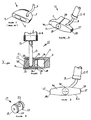
- FIG 2 there is shown a golf putter 10 in accordance with the present invention.
- Golf putter 10 comprises a generally T-shaped head 11 connected to a shaft 12 by means of a hosel member 13.
- Hosel member 13 may be hollow.
- a shaft connection may comprise the hosel member 13 or the hosel member 13 may be dispensed with and the shaft connection may comprise a shaft 14 connected directly to the head 11 .
- the head 11 comprises an outer shell member 15 which defines a cavity 16 within the head 11.
- An important part of the present invention is the use of a cylindrical inner insert member 17 located within cavity 16 of head 11.
- Insert member 17 is made of bronze material and defines a rear cavity 18.
- the bronze material is selected to be a soft ductile material to facilitate the transmission of shock.
- a sweet spot 19 of the head 11 is arranged to be at the centre of the circular face area of insert 17 as indicated by the crossed lines as best seen in figure 4.
- An aperture 20 is formed in insert 17 by drilling and reaming to receive and ensure a proper fit with either hosel 13 or shaft 14. As seen in figure 2 hosel member 13 stops short of the end of the aperture 20 so that it does not contact outer shell member 15. It is believed this arrangement enhances the transmission of impact energy to the putter shaft as feel.
- Cavity 18 in combination with the remaining part of cavity 16 defines a void 21 in head 11. Void 21 is believed to increase the resonance factor of head 11.
- Insert 17 is supported and fixed within cavity 16 by means of Neoprene resilient O-rings 22, 23 fitted to semi-circular grooves 24, 25 formed around the circular periphery of insert 17.
- a small clearance exists between insert 17 and a shoulder 26 formed within outer shell member 15.
- the O-rings 22,23 space the insert 17 from outer shell member 15 so that a small clearance 31 is formed which in a sense insulates insert 17 from outer shell member 15.
- Stabilising or inertia weights 27 are let into the sides 28 of the head 11 to minimise the effect of off-centre hits.
- a slot 29,see figure 5, assists in aiming the striking face 30 of the putter head 11.
- Outer shell member 15 and hosel member 13 are made of aircraft quality high strength aluminium and when shaft 12,14 comprises a substantially large diameter shaft the shaft will be made of carbon fibre material.
- the O-rings act as seals to prevent dirt and moisture from entering void 21 through clearance 31.
- Shaft 14 or hosel member 13 enters the aperture 20 in insert 17 through a hole 29 drilled in outer shell member 15.
- a golf club for example a putter as shown in figure 2 may have an increased "feel factor" due to the increased energy being transmitted up the shaft 12, 14. It has been found in practice that the void 21 also enhances the feel factor.
- the present invention may be used with so called standard shafts. However, the invention can be most advantageously used in a putter with a substantially large diameter (between 25 and 45mm), thin walled, parallel shaft to enhance the "feel factor".
- the present invention may be used in golf clubs other than putters but in that case due care must be taken with the design because of the higher forces that may be involved.
Landscapes
- Health & Medical Sciences (AREA)
- General Health & Medical Sciences (AREA)
- Physical Education & Sports Medicine (AREA)
- Golf Clubs (AREA)
Description
- This invention relates to a golf club. More particularly the invention is concerned with the provision of a novel connection between the head of a golf club and the shaft. In prior art golf clubs as shown in figure 1 a golf club 1 comprises a
head 2 connected to ashaft 3. thehead 2 has astriking face 4 with a so called sweet-spot 5 which is usually arranged to occur at the geometrical centre of area of thestriking face 4 as indicated by the crossed lines. Ideally impact with a golf ball is sought to take place at the sweet-spot 5. A problem with this prior art arrangement is that theshaft 3 is displaced somewhat from the impact area and is fixed directly to thehead 2. As a consequence of this some of the energy of impact is dissipated within the head thus lessening the amount of impact energy which can be transmitted up the shaft to the player's hands so that in one sense the amount of energy available to define "feel" is reduced. - A number of arrangements have been proposed which aim to assist the golfer in striking the golf ball correctly. For example, US5,090,698 describes a golf putter in which the sweet spot is effectively extended over much of the striking surface. However, the striking face forms part of the golf club head itself and therefore a significant proportion of the impact energy is dissipated within the head with the disadvantageous effects described above.
- US4,411,430 discloses a golf putter having an eccentrically weighted portion inside the golf club head which may be rotated to shift the axial centre of mass of the head. This enables the golfer to correct manufacturing variations and to correct errors in the putting stroke. However, the striking surface of the putter effectively forms an integral part of the golf club head and similarly can result in reduced "feel" sensed by the player.
- According to the present invention there is provided, a golf club having a head including a striking face with a sweet spot, the head comprising an outer shell member defining a cavity, an inner insert member located within the cavity spaced from the outer shell member and defining the sweet spot, and a shaft connection fixed to the inner insert member through the outer shell member, characterized in that the inner insert member is resiliently supported and resiliently fixed within the cavity such that a clearance space exists between the inner insert member and the outer shell member.
- The present invention will now be described by way of example only and with reference to the accompanying drawings wherein:
- Figure 1 is a prior art golf club and connection.
- Figure 2 is a part sectional elevation of a golf putter in accordance with the present invention.
- Figure 3 is a part elevational view looking on arrow "A" of figure 2
- Figure 4 is a perspective view of an insert used in the practice of the invention.
- Figure 5 is a perspective view of a putter head and shaft connection in accordance with the present invention.
-
- In figure 2 there is shown a golf putter 10 in accordance with the present invention. Golf putter 10 comprises a generally T-shaped head 11 connected to a shaft 12 by means of a
hosel member 13. Hoselmember 13 may be hollow. A shaft connection may comprise thehosel member 13 or thehosel member 13 may be dispensed with and the shaft connection may comprise a shaft 14 connected directly to the head 11 . The head 11 comprises anouter shell member 15 which defines acavity 16 within the head 11. An important part of the present invention is the use of a cylindricalinner insert member 17 located withincavity 16 of head 11.Insert member 17 is made of bronze material and defines arear cavity 18. The bronze material is selected to be a soft ductile material to facilitate the transmission of shock. Asweet spot 19 of the head 11 is arranged to be at the centre of the circular face area ofinsert 17 as indicated by the crossed lines as best seen in figure 4. Anaperture 20 is formed ininsert 17 by drilling and reaming to receive and ensure a proper fit with eitherhosel 13 or shaft 14. As seen in figure 2hosel member 13 stops short of the end of theaperture 20 so that it does not contactouter shell member 15. It is believed this arrangement enhances the transmission of impact energy to the putter shaft as feel.Cavity 18 in combination with the remaining part ofcavity 16 defines a void 21 in head 11. Void 21 is believed to increase the resonance factor of head 11.Insert 17 is supported and fixed withincavity 16 by means of Neoprene resilient O-rings semi-circular grooves insert 17. A small clearance exists betweeninsert 17 and ashoulder 26 formed withinouter shell member 15. Also as best seen in figure 2 the O-rings insert 17 fromouter shell member 15 so that asmall clearance 31 is formed which in a sense insulates insert 17 fromouter shell member 15. Stabilising orinertia weights 27 are let into thesides 28 of the head 11 to minimise the effect of off-centre hits. Aslot 29,see figure 5, assists in aiming thestriking face 30 of the putter head 11.Outer shell member 15 andhosel member 13 are made of aircraft quality high strength aluminium and when shaft 12,14 comprises a substantially large diameter shaft the shaft will be made of carbon fibre material. In addition to resiliently fixinginsert 17 withincavity 16 the O-rings act as seals to prevent dirt and moisture from entering void 21 throughclearance 31. Shaft 14 orhosel member 13 enters theaperture 20 ininsert 17 through ahole 29 drilled inouter shell member 15. As can be appreciated from figure 3 becauseinsert 17 is insulated fromouter shell member 15 by the resilient O-rings any impact oninsert 17 is transferred more or less directly to shaft 14 orhosel 13 with less impact energy being dissipated within head 11. Consequently a golf club, for example a putter as shown in figure 2 may have an increased "feel factor" due to the increased energy being transmitted up the shaft 12, 14. It has been found in practice that the void 21 also enhances the feel factor. The present invention may be used with so called standard shafts. However, the invention can be most advantageously used in a putter with a substantially large diameter (between 25 and 45mm), thin walled, parallel shaft to enhance the "feel factor". The present invention may be used in golf clubs other than putters but in that case due care must be taken with the design because of the higher forces that may be involved.
Claims (15)
- A golf club (10) having a head (11) including a striking face (30) with a sweet spot (19), the head comprising an outer shell member (15) defining a cavity (16), an inner insert member (17) located within the cavity (16) spaced from the outer shell member (15) and defining the sweet spot (19), and a shaft connection (12,14) fixed to the inner insert member (17) through the oxter shell member (15), characterized in that the inner insert member (17) is resiliently supported and resiliently fixed within the cavity (16) such that a clearance space (31) exists between the inner insert member (17) and the outer shell member (15).
- A golf club (10) according to claim 1, wherein the inner insert member (17) is supported and resiliently fixed by resilient O-rings (22,23).
- A golf club (10) according to claim 2, wherein the resilient O-rings (22,23) comprise the material Neoprene.
- A golf club according to claim 2 or claim 3, wherein the inner insert member (17) comprises a rear cavity (18) which, together with at least a portion of the cavity (16), forms a void (21) within the head (11), the void (21) being sealed by the O-rings (22,23).
- A golf club (10) according to any of claims 2 to 4, wherein the inner insert member (17) further comprises grooves (24,25) formed around its circumference to receive the resilient O-rings (22,23).
- A golf club (10) according to any of the preceding claims, wherein the shaft connection (12,14) fits within an aperture (20) formed in the inner insert member (17) and stops short of the end of the aperture (20) so that it does not contact the outer shell member (15).
- A golf club (10) according to any of the preceding claims, wherein the shaft connection (12,14) comprises a hosel member (13) fitted to the insert.
- A golf club (10) according to claim 7, wherein the hosel member (13) is hollow.
- A golf club (10) according to claim 7 or claim 8, wherein the shaft connection (12,14) further comprises a shaft (14) fitted to the hosel member (13).
- A golf club according to any of claims 1 to 6, wherein the shaft connection (12,14) comprises a shaft (14).
- A golf club (10) according to claim 9 or claim 10, wherein the shaft (14) has a diameter of between 25 and 45mm.
- A golf club (10) according to any of the preceding claims, wherein a shoulder (26) is formed within the cavity (16) of outer shell member (15), and a clearance space exists between the inner insert member (17) and the shoulder (26).
- A golf club (10) according to any of claims 7 to 9 or 11 to 12, wherein the outer shell member (15) and the hosel member (13) are made of high strength aircraft quality aluminum.
- A golf club (10) according to any of the preceding claims, wherein the inner insert member (17) is made of a soft ductile bronze material.
- A golf club (10) according to any of the preceding claims, the club (10) comprising a putter.
Applications Claiming Priority (2)
| Application Number | Priority Date | Filing Date | Title |
|---|---|---|---|
| GB9812942 | 1998-06-17 | ||
| GB9812942A GB2338189B (en) | 1998-06-10 | 1998-06-17 | Golf club and connection therefor |
Publications (2)
| Publication Number | Publication Date |
|---|---|
| EP0965366A1 EP0965366A1 (en) | 1999-12-22 |
| EP0965366B1 true EP0965366B1 (en) | 2004-12-08 |
Family
ID=10833833
Family Applications (1)
| Application Number | Title | Priority Date | Filing Date |
|---|---|---|---|
| EP99304704A Expired - Lifetime EP0965366B1 (en) | 1998-06-17 | 1999-06-16 | Golf putter |
Country Status (3)
| Country | Link |
|---|---|
| EP (1) | EP0965366B1 (en) |
| JP (1) | JP2000024148A (en) |
| DE (1) | DE69922438T2 (en) |
Families Citing this family (5)
| Publication number | Priority date | Publication date | Assignee | Title |
|---|---|---|---|---|
| US7037211B1 (en) | 1999-08-10 | 2006-05-02 | Chapel Golf, Inc. | Golf club |
| US6692376B2 (en) | 1999-08-10 | 2004-02-17 | Chapel Golf, Inc. | Golf club |
| US6503151B2 (en) | 2000-03-24 | 2003-01-07 | Chapel Golf, Inc. | Golf club |
| GB2373733B (en) * | 2001-03-15 | 2004-08-18 | Douglas Boyd Buchanan | Putter head with pre-machined insert |
| US6860820B2 (en) | 2002-08-14 | 2005-03-01 | Chapel Golf, Inc. | Golf club and methods of manufacture |
Family Cites Families (8)
| Publication number | Priority date | Publication date | Assignee | Title |
|---|---|---|---|---|
| US3206206A (en) * | 1963-05-09 | 1965-09-14 | James W Santosuosso | Golf putter including angularly and rotatably relatively adjustable head and shaft |
| US3387844A (en) * | 1964-11-18 | 1968-06-11 | Winsor Shippee | Golf club with percussion chamber plenum |
| US3873094A (en) * | 1972-03-10 | 1975-03-25 | Alexander Sebo | Putter-type golf club |
| US4324404A (en) * | 1980-05-19 | 1982-04-13 | Walter Dian, Inc. | Golf putter |
| US4411430A (en) * | 1980-05-19 | 1983-10-25 | Walter Dian, Inc. | Golf putter |
| US5090698A (en) * | 1990-03-27 | 1992-02-25 | Kleinfelter Thomas A | Golf putter |
| FR2672226A1 (en) * | 1991-02-06 | 1992-08-07 | Desbiolles Jack | Head for a golf club |
| US5632694A (en) * | 1995-11-14 | 1997-05-27 | Lee; Doo-Pyung | Putter |
-
1999
- 1999-06-16 DE DE69922438T patent/DE69922438T2/en not_active Expired - Fee Related
- 1999-06-16 EP EP99304704A patent/EP0965366B1/en not_active Expired - Lifetime
- 1999-06-17 JP JP11171155A patent/JP2000024148A/en active Pending
Also Published As
| Publication number | Publication date |
|---|---|
| JP2000024148A (en) | 2000-01-25 |
| DE69922438T2 (en) | 2005-04-07 |
| EP0965366A1 (en) | 1999-12-22 |
| DE69922438D1 (en) | 2005-01-13 |
Similar Documents
| Publication | Publication Date | Title |
|---|---|---|
| US5575723A (en) | Golf club with cushion material between shaft and head | |
| KR200280906Y1 (en) | Golf club head with visual indicator | |
| US6206790B1 (en) | Iron type golf club head with weight adjustment member | |
| US6186903B1 (en) | Golf club head with loft and lie adjustment notch | |
| US6620053B2 (en) | Golf club | |
| US5595552A (en) | Golf club head with tuning and vibration control means | |
| US6551199B2 (en) | Inertia capsule for golf club | |
| US6482106B2 (en) | Wood-type club | |
| US20040121850A1 (en) | Putter grip with improved vibration transmission to hands | |
| US20070238551A1 (en) | Golf club head | |
| US20050009632A1 (en) | Iron type golf club head with low profile tuning port | |
| US5538246A (en) | Golf club | |
| US20020132683A1 (en) | Putter head with pre-machined insert | |
| US6077172A (en) | Metal wood golf club head having a shaft attachment at the sole | |
| US7435188B2 (en) | Golf putter head | |
| US5797806A (en) | Golf club having shock isolation between the head and the shaft | |
| WO1996014109A1 (en) | Golf putter head | |
| US6517447B2 (en) | Golf club and connection therefor | |
| US5766089A (en) | Golf club | |
| EP0965366B1 (en) | Golf putter | |
| US20050215345A1 (en) | Golf club | |
| GB2338189A (en) | Golf club with insert in head providing golfer with more 'feel' | |
| US8920260B1 (en) | Golf club putter with roller putting head | |
| JPH06105937A (en) | Wood golf club | |
| US6024653A (en) | Heel-to-toe balanced golf club head |
Legal Events
| Date | Code | Title | Description |
|---|---|---|---|
| PUAI | Public reference made under article 153(3) epc to a published international application that has entered the european phase |
Free format text: ORIGINAL CODE: 0009012 |
|
| AK | Designated contracting states |
Kind code of ref document: A1 Designated state(s): DE FR SE |
|
| AX | Request for extension of the european patent |
Free format text: AL;LT;LV;MK;RO;SI |
|
| AKX | Designation fees paid | ||
| REG | Reference to a national code |
Ref country code: DE Ref legal event code: 8566 |
|
| 17P | Request for examination filed |
Effective date: 20000825 |
|
| RBV | Designated contracting states (corrected) |
Designated state(s): DE FR SE |
|
| RAP3 | Party data changed (applicant data changed or rights of an application transferred) |
Owner name: BUCHANAN GOLF LIMITED |
|
| 17Q | First examination report despatched |
Effective date: 20030912 |
|
| GRAP | Despatch of communication of intention to grant a patent |
Free format text: ORIGINAL CODE: EPIDOSNIGR1 |
|
| RIN1 | Information on inventor provided before grant (corrected) |
Inventor name: BUCHANAN, DOUGLAS BOYD |
|
| RAP1 | Party data changed (applicant data changed or rights of an application transferred) |
Owner name: BUCHANAN GOLF LIMITED |
|
| GRAS | Grant fee paid |
Free format text: ORIGINAL CODE: EPIDOSNIGR3 |
|
| GRAA | (expected) grant |
Free format text: ORIGINAL CODE: 0009210 |
|
| AK | Designated contracting states |
Kind code of ref document: B1 Designated state(s): DE FR SE |
|
| REF | Corresponds to: |
Ref document number: 69922438 Country of ref document: DE Date of ref document: 20050113 Kind code of ref document: P |
|
| REG | Reference to a national code |
Ref country code: SE Ref legal event code: TRGR |
|
| PG25 | Lapsed in a contracting state [announced via postgrant information from national office to epo] |
Ref country code: SE Free format text: LAPSE BECAUSE OF NON-PAYMENT OF DUE FEES Effective date: 20050617 |
|
| ET | Fr: translation filed | ||
| PLBE | No opposition filed within time limit |
Free format text: ORIGINAL CODE: 0009261 |
|
| STAA | Information on the status of an ep patent application or granted ep patent |
Free format text: STATUS: NO OPPOSITION FILED WITHIN TIME LIMIT |
|
| 26N | No opposition filed |
Effective date: 20050909 |
|
| PG25 | Lapsed in a contracting state [announced via postgrant information from national office to epo] |
Ref country code: DE Free format text: LAPSE BECAUSE OF NON-PAYMENT OF DUE FEES Effective date: 20060103 |
|
| EUG | Se: european patent has lapsed | ||
| PG25 | Lapsed in a contracting state [announced via postgrant information from national office to epo] |
Ref country code: FR Free format text: LAPSE BECAUSE OF NON-PAYMENT OF DUE FEES Effective date: 20060228 |
|
| REG | Reference to a national code |
Ref country code: FR Ref legal event code: ST Effective date: 20060228 |