EP0964628B1 - Method and device for trimming and end-rounding bristles - Google Patents
Method and device for trimming and end-rounding bristles Download PDFInfo
- Publication number
- EP0964628B1 EP0964628B1 EP98910173A EP98910173A EP0964628B1 EP 0964628 B1 EP0964628 B1 EP 0964628B1 EP 98910173 A EP98910173 A EP 98910173A EP 98910173 A EP98910173 A EP 98910173A EP 0964628 B1 EP0964628 B1 EP 0964628B1
- Authority
- EP
- European Patent Office
- Prior art keywords
- filaments
- group
- jaws
- filament
- rounding
- Prior art date
- Legal status (The legal status is an assumption and is not a legal conclusion. Google has not performed a legal analysis and makes no representation as to the accuracy of the status listed.)
- Expired - Lifetime
Links
- 238000000034 method Methods 0.000 title claims description 25
- 238000009966 trimming Methods 0.000 title claims description 14
- 238000005520 cutting process Methods 0.000 claims description 36
- 238000006073 displacement reaction Methods 0.000 claims description 2
- 238000004519 manufacturing process Methods 0.000 description 5
- 238000009732 tufting Methods 0.000 description 4
- 230000001680 brushing effect Effects 0.000 description 2
- 230000000694 effects Effects 0.000 description 2
- 239000004677 Nylon Substances 0.000 description 1
- 241000904500 Oxyspora paniculata Species 0.000 description 1
- 238000005299 abrasion Methods 0.000 description 1
- 239000002253 acid Substances 0.000 description 1
- 239000000428 dust Substances 0.000 description 1
- 230000002401 inhibitory effect Effects 0.000 description 1
- 239000000463 material Substances 0.000 description 1
- 229920001778 nylon Polymers 0.000 description 1
- 238000004806 packaging method and process Methods 0.000 description 1
- 238000002360 preparation method Methods 0.000 description 1
- HBMJWWWQQXIZIP-UHFFFAOYSA-N silicon carbide Chemical compound [Si+]#[C-] HBMJWWWQQXIZIP-UHFFFAOYSA-N 0.000 description 1
- 229910010271 silicon carbide Inorganic materials 0.000 description 1
- 239000000126 substance Substances 0.000 description 1
- 230000003746 surface roughness Effects 0.000 description 1
- 239000002699 waste material Substances 0.000 description 1
Images






Classifications
-
- A—HUMAN NECESSITIES
- A46—BRUSHWARE
- A46D—MANUFACTURE OF BRUSHES
- A46D9/00—Machines for finishing brushes
- A46D9/02—Cutting; Trimming
-
- A—HUMAN NECESSITIES
- A46—BRUSHWARE
- A46D—MANUFACTURE OF BRUSHES
- A46D1/00—Bristles; Selection of materials for bristles
- A46D1/04—Preparing bristles
- A46D1/05—Splitting; Pointing
-
- A—HUMAN NECESSITIES
- A46—BRUSHWARE
- A46D—MANUFACTURE OF BRUSHES
- A46D1/00—Bristles; Selection of materials for bristles
- A46D1/04—Preparing bristles
- A46D1/06—Machines or apparatus for cutting bristles
Definitions
- the present invention relates to methods and devices for trimming and end-rounding bristles, e.g., bristles used in toothbrushes.
- Brushes of many types are formed by mounting a plurality of bristles, typically arranged in tufts, on a brush body so that the tips of the bristles together define a brushing surface.
- Some applications further require that the tips of the bristles be "end-rounded", i.e., that the shape of the tips be altered from the typical blunt-cut flat tip surface that is present after trimming to a smooth, relatively hemispherical tip shape. End-rounding is particularly important when the bristles are to be used in a toothbrush, as the sharp edges of blunt-cut bristle tips may contribute to gingival abrasion and/or cause discomfort to the toothbrush user.
- U.S. Patent 5,431,484 (upon which the preamble of ind. claims 1 and 12 is based) discloses an apparatus for processing bristle) bundles.
- a forward feed device positions the bristle strand ends for end-rounding with the aid of a moveable clamping grip.
- the clamping grip grasps the bristle strands securely and the strands are conveyed to the grinding device by means of displacement of the forward feed device.
- DE-A-195 25 808 also deals with a device for processing bristle strands, and also includes a moveable clamping device for securing the bristle strands together.
- DE-U-9107687.0 relates to a device for end-rounding bristles for a toothbrush.
- a rotating belt grinder has a constant grinding speed relative to the width of the grinding belt for even processing of bristle ends.
- the additional rotational movement of the belt grinder provides that the grinding of bristle ends occurs from all circumferential directions.
- the present invention provides an improved process for end-rounding and trimming filaments, and cutting the end-rounded filaments to length to form bristles.
- the bristles are formed by providing continuous filaments of bristle stock, gathering the filaments together to form a group of filaments arranged so that the longitudinal axis of each filament is substantially parallel to the longitudinal axes of the other filaments and the ends of the filaments define a plane, end-rounding the ends of the filaments as they are held in the group, and cutting off a length of the grouped filaments to define a cut bundle.
- the filaments can be fed to the device from a spool or other packaging on which the continuous filaments are wound or contained (e.g., an unwound hank), and the cut bundles can be transferred easily to a magazine from which the bristles are fed to a tufting machine.
- a spool or other packaging on which the continuous filaments are wound or contained e.g., an unwound hank
- the invention features a method of trimming and end-rounding bristles.
- the method includes (a) providing a group of elongated continuous filaments arranged so that the longitudinal axis of each of the filaments is substantially parallel to the longitudinal axes of the other filaments and so that the ends of the filaments define a plane; (b) providing a device for trimming and end-rounding bristles that includes (i) a filament advancing device constructed to receive the filament group from a guide structure and advance the group of filaments, comprising a pair of vertically movable jaws, being movable between an open position in which the group of filaments is axially movable with respect to the jaws and a closed position in which the jaws grasp the group of filaments; (ii) an end-rounding device positioned to engage the ends of said elongated filaments when delivered by said guide structure and to end-round said ends; and (iii) a cutter constructed to cut said filaments at a predetermined distance from said end-rounded ends to form
- the cutting step is performed using a guillotine cutter and the end-rounding is performed using a belt end-rounder.
- the guide structure includes a guide tube constructed to gather the filaments into the group, and an advancement gripper constructed to grasp the group of filaments and move the group of filaments to a position in which their ends engage the end-rounding device. Between steps (d) and (e), the fixed pair of jaws is closed to grasp the groups of filaments and thereby restrict radial movement of the filaments.
- Preferred devices further include a transfer gripper constructed to engage the cut bundle and transfer the cut bundle to a predetermined location spaced from the device.
- preferred devices When the continuous filaments are provided in the form of a hank wound on a spool, preferred devices further include a plurality of rollers over which said continuous filaments are passed, when said device is in use, the rollers being constructed to direct the filaments into the guide structure.
- the filament group includes a sufficient number of filaments to manufacture a plurality of toothbrushes. It is also preferred that the guide structure, filament advancing device, end-rounding device, and cutting device be substantially vertically aligned.
- the invention features a device for trimming and end-rounding bristles.
- the method and device of the invention allow filaments to be trimmed and end-rounded easily prior to attachment to a brush.
- excellent end-rounding can be achieved due to the expanded ability to select the desired residence time and other parameters during end-rounding (if end-rounding is performed after tufting, the residence time often is determined by the speed of the tufting machine).
- waste from trimming is reduced, and the efficiency of the brush manufacturing process can be dramatically improved.
- a device (10) for trimming and end-rounding bristles comprises:
- the guide structure, the filament advancing device, the end-rounding device and the cutting device are substantially vertically aligned.
- the invention features a method of forming a toothbrush.
- the method includes trimming and end-rounding a plurality of filaments as described above to form bristles having a predetermined length, providing a toothbrush head, and mounting a plurality of the bristles on the toothbrush head.
- the invention also features bristles having improved end-rounding characteristics.
- the shape of the bristle ends can be predetermined, e.g., the bristle ends can be shaped flat, half spherical, pencil point or any conical shape desired, depending on how the machine is configured, as would be understood by one skilled in the art.
- guillotine refers to a blade that is constructed to shear through a plurality of filaments without substantial tearing of the filaments.
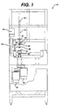
- Fig. 1 is a schematic end view of a device according to one embodiment of the invention.
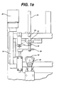
- Fig. 1 a is a detailed view of a portion of the device of Fig. 1 (for clarity, the cutter mechanism is omitted from Fig. 1 a).
- Fig. 1 b is a side view of the device of Fig. 1, showing the feed path for elongated filaments wound on a spool.
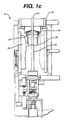
- Fig. 1c is a detailed end view of the device, showing the feed path from above.
- Fig. 2 is a schematic top view of the cutter mechanism of the device of Fig. 1.
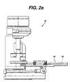
- Fig. 2a is a side view of the cutter mechanism.
- Fig. 2b is an enlarged detail view of a portion of the cutter mechanism.
- Fig. 3 is a top view of the advancement gripper used in the device of Fig. 1, in its open position.
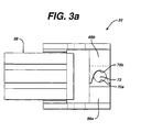
- Fig. 3a shows the advancement gripper in its closed position.
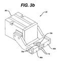
- Fig. 3b is a perspective view of the advancement gripper in its closed position.
- Fig. 4 is a schematic side view illustrating the splaying out of the filaments during contact with the end-rounding device.
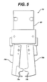
- Fig. 5 is a top view in the open position
- Fig. 5a is a top view in the closed position
- Fig. 5b is a side view, of the transfer gripper used in Fig. 1.
- a preferred device 10 includes a spool 12 (Fig. 1b) from which a plurality of continuous filaments 14 are drawn. From the spool 12, the filaments 14 pass through a series of guide rollers 16, 18, 20, 22. The rollers have-a "bow-tie” shaped axial cross-section (see Fig. 1c), so that the filaments are directed together toward the center of the roller surface, gathering them together. To enhance this gathering effect it is preferred that the rollers further from the spool have a more steeply pitched "bow-tie" shaped cross-section than those that are closer to the reel, so as the filaments pass through the successive rollers they are gradually gathered more and more closely together. This arrangement has been found to effectively control "unruly" filaments as they are unwound from the spool and pass through the process, inhibiting the tendency of the filaments to bulk up and resist feeding.
- the gathered filaments 14 are fed into a guide tube 24 having a funnel-shaped portion 26 at its upper end to help guide and further gather the filaments as they enter the guide tube 24.
- the filaments are fed through the guide tube until their gathered ends exit the lower end 28 of the guide tube and pass through hold grippers 30 and advancement grippers 32.
- the ends of the filaments are then grasped and held in this position by hold grippers 30 (Figs. 1 and 1a).
- the advancement grippers 32 and hold grippers 30 are substantially identical and are shown in detail in Figs. 3 and 3a and described below.
- the hold grippers 30 are mounted in a stationary position, and do not move in the vertical plane.
- the jaws of the hold grippers open and close, as shown in Figs. 3 and 3a, respectively, to grasp or release the filament group.
- the device has been prepared for use, and the filament group can now be cut into end-rounded lengths on a substantially continuous basis, i.e., without repeating the above initial feeding process.
- the filament group 14 is next grasped by advancement grippers 32, and released by hold grippers 30.
- Advancement grippers 32 like hold grippers 30, are movable between the open and closed positions shown in Figs. 3 and 3a.
- Advancement grippers 32 are also moveable between a plurality of positions in the vertical plane, e.g., a raised position (shown in Figs. 1 and la) and several lowered positions, by a linear actuator.
- the linear actuator includes a ball carriage 34 driven by an actuator 36 such as a servomotor or stepper motor.
- advancement grippers 32 are next moved, still grasping the group, from the raised position to a lowered position. This feeds the filament group through the bottom guide 38.
- the bottom guide includes an aperture slightly larger than the diameter of the group, through which the group extends.
- Bottom guide 38 is movable between a raised, normal position, in which it is out of the way of the cutting device, and a lowered, guide position, in which it guides the filament group during end-rounding.
- the bottom guide 38 is biased, e.g., spring-biased towards its raised position (Figs. 1 and 1a), and is pushed towards its lowered position by the driven advancement grippers 32.
- bottom guide 38 In its lowered position, bottom guide 38 is positioned at a predetermined height above the end-rounding device, selected to optimize the degree of "splay" of the bristles during end-rounding, as will be discussed below.
- belt end-rounder 40 actuated, i.e., the two motors 44, 46 (Fig. 1) that drive the rotation of the belts of the end-rounder are turned on. It is preferred that the end-rounder be actuated prior to any contact with the filament ends, otherwise the filaments may tend to bend in an undesirable manner, e.g., kink, or to be forced back through the advancement gripper as the actuator advahces the ball screw. If desired, the end-rounder may be operated continuously so that it is not necessary to coordinate turning the end-rounder on with lowering of the filament group.
- the hold gripper 30 is closed prior to engagement of the ends of the filament group with the belt end-rounder, to stabilize the filament group during end-rounding.
- the extent of splay will be determined by several factors: (a) the length of the filament group that extends below the bottom guide 38, (b) the diameter of the group, as well as the diameter of the individual filaments, (d) the "interference distance" between the filament group and the belt, i.e., the amount by which the filament group would extend below the end-rounder belt if there were an aperture in the belt through which the group could extend (the filaments being instead deflected outwardly by pressure exerted against the belt), (e) the driven speed of the end-rounding belts, and (f) the surface roughness of the end-rounding belts.
- the driven speed will often be dictated by the speed required to keep pace with other steps in the brush manufacturing process.
- the filament ends walk around in a circle" on the belt surface during end-rounding. If the filament ends do not move around the belt surface at all, generally the ends of the filaments will just be sanded flat, rather than end-rounded.
- the above factors can be adjusted empirically to obtain the desired degree of end-rounding by observing the resulting condition of the filament ends after completion of the process and varying any or all of these parameters as needed, as would be understood by one skilled in the art.
- a vacuum shroud is provided adjacent the end-rounding device, to remove the dust generated during end-rounding, as is well known in the art.
- the filament group is raised to a predetermined position relative to the cutting device 48 by the advancement grippers 32 in preparation for cutting a length of the end-rounded filaments for use as bristles.
- the predetermined position is determined by the length of bristle that is desired.
- the filament group When the filament group is in the desired position, it is grasped by the advance and hold grippers above the cutting device, and by a transfer gripper 70 (shown in detail in Figs. 5, 5a and 5b) below the cutting device. Holding the filament group above the cutting device insures an accurate cut at the desired length. Additionally, the hold grippers maintain the desired filament position after cutoff. Grasping the filament group below the cutting device allows the cut portion of the group to be held together and transferred to another location, for example, to a filament magazine. In a toothbrush manufacturing process, the cut portion would be transferred to a filament magazine at a tufting station.
- Cutting device 48 includes a plate 50 having a cutting aperture 52 for receiving the filament group.
- Cutting aperture 52 includes a chamfer 54 which is angled to direct the filament ends into the aperture.
- Guillotine blade 56 reciprocates between a normal position (shown in solid lines in Fig. 2) and a cutting position (shown in phantom lines in Fig. 2) in the manner of a guillotine. The inventors have found that, by cutting the filaments in this manner, uniform flat ends are obtained without tearing of the filaments. This result remains relatively consistent even after minor blade wear occurs.
- Guillotine blade 56 includes an angled cutting edge 58 (Fig. 2b), to further ensure that the filaments will be sheared cleanly rather than torn.
- the reciprocation of the guillotine blade is actuated by rotation of crankshaft 59 (Fig. 2), displacing eccentric cam 60 from the position shown in solid lines through the positions shown in phantom lines in Fig. 2.
- the eccentric cam displaces bearing 62 against biasing spring 64 (which biases the guillotine blade 56 towards its normal position), forcing the guillotine blade forward through the filament group.
- the advancement gripper 32 and the hold gripper 30 are substantially identical. Accordingly, both are shown in Figs. 3-3b. These figures will be described with reference to the advancement gripper, for convenience; the following description, however, applies to both grippers.
- Advancement gripper 32 includes a pair of jaws 66a, 66b, that are moved between open (Fig. 3) and closed (Figs. 3a, 3b) positions by a pneumatic gripper 68.
- Jaws 66a, 66b include arcuate portions 70a, 70b that together define an aperture 72 of variable diameter.
- the diameter of aperture 72 is significantly greater than that of the filament group, allowing the gripper to be moved axially up and down the length of the filament group.
- the diameter of aperture 72 is substantially equal to the outer diameter of the filament group (in a compressed state), allowing the gripper to grasp the filament group securely.
- jaws 66a, 66b preferably include interlocking fingers 74 to enable the jaws to be moved between their positions in a controlled manner without less of filament containment.
- the transfer grippers 70 include a pair or jaws 76a, 76b that include arcuate portions 78a, 78b, and an actuator 80 that moves the jaws between an open position (Fig. 5) and a closed position (Fig. Sa).
- the arcuate portions 78a, 78b are completely separated, i.e., do not define an aperture.
- the arcuate portions 78a, 78b define an aperture 82 having a diameter that is substantially equal to the outer diameter of the cut bundle, allowing the grippers 70 to firmly grasp the cut bundle.
- the interference distance was approximately 0.229 cm (0.090 inch).
- the abrasive medium (end-rounder belt) was 280 grit silicon carbide.
- the speed of the abrasive medium was approximately 70 inches/second, and the orbital speed of the end-rounder head (speed of rotation in the plane parallel to the plane defined by the ends of the filaments) was approximately 1000 rpm.
- the duration of contact of the filament end contact with the abrasive medium was approximately 8 seconds.
- end-rounding device need not be a belt end-rounder, as shown, but could instead be any other device that will produce end-rounding of the filaments chosen.
- suitable end-rounding devices include but are not limited to belt end-rounders, drum end-rounders, chemical end-rounders (e.g., an acid bath), heat end-rounders and ultrasonic end-rounders.
- filaments can be used, provided the filament has sufficient structural integrity to withstand the process, which can be easily determined empirically.
- the filaments When the bristles are to be used in toothbrush manufacture, the filaments would be selected to be suitable for such use. Suitable toothbrush bristle materials are well known to those skilled in the art.
- the filaments have been illustrated as being wound on a spool, the filaments could be provided in any desired manner, e.g., as an unwound hank. If the filaments were provided in a different manner, the feed path used would change (would no longer be the rollers illustrated in Figs. 1-1c). For example, if an unwound hank of filaments were used, the filaments could be fed through an elongated tube.
Landscapes
- Brushes (AREA)
Description
Claims (24)
- A method for trimming and end-rounding bristles comprising:(a) providing a group of elongated continuous filaments arranged so that the longitudinal axis of each of the filaments is substantially parallel to the longitudinal axes of the other filaments;(b) providing a device for trimming and end-rounding bristles comprising:a filament advancing device constructed to receive the filament group from a guide structure and advance the group of filaments, comprising a pair of vertically movable jaws (32), movable between an open position in which the group of filaments is axially movable with respect to the jaws and a closed position in which the jaws grasp the group of filaments;an end-rounding device (40) positioned to engage the ends of said elongated filaments when delivered by said guide structure and to end-round said ends; anda cutter (48) constructed to cut said filaments at a predetermined distance from said end-rounded ends to form a cut bundle of bristles of predetermined length;(c) closing the pair of vertically movable jaws (32) to grasp the group of filaments;(d) moving the pair of jaws vertically to advance the group of filaments to an end-rounding device (40);(e) contacting the free ends. of the filament group with the end-rounding device to end-round the group of filaments; and(f) cutting the filaments with the cutting device (48) to define a bundle of end-rounded bristles having a predetermined length; characterized in that said filament advancing device further comprises a pair of jaws (30) that is fixed against vertical movement, said jaws being movable between an open position in which the group of filaments is axially movable with respect to the jaws and a closed position in which the jaws grasp the group of filaments.
- The method of claim 1, further comprising providing a third pair of jaws constructed to grasp the filament group below the cutting device, and, during step (f), grasping the filaments above the cutting device with at least one of the fixed or vertically movable pairs of jaws and grasping the filaments below the cutting device with the third pair of jaws to stabilize the filaments and cut bristles during and after cutting.
- The method of claim 1, further comprising providing a third pair of jaws, constructed to grasp the group of filaments in a region below the cutting device, and grasping the group of filaments with the third pair of jaws prior to cutting the filaments.
- The method of any of claims 1-3, further comprising providing a guide member, mounted above the end-rounding device, having an aperture dimensioned to receive the group of filaments, and inserting the group of filaments through the guide member to further restrict radial movement of the filaments.
- The method of any of the preceding claims, further comprising providing said elongated filaments wound on a spool.
- The method of claim 5, further comprising unwinding said elongated filaments from said spool.
- The method of any of the preceding claims, wherein said delivering step comprises passing the elongated filaments through a series of rollers constructed to gather the filaments into said group.
- The method of any of the preceding claims, wherein said cutting step is performed using a guillotine cutting device.
- The method of any of the preceding claims, further comprising selecting said predetermined length so that said bristle is suitable for use as a toothbrush bristle.
- The method of any of the preceding claims, further comprising selecting said filament group to contain sufficient filaments to form a plurality of toothbrushes.
- The method of any of the preceding claims, further comprising between steps (d) and (e), closing the fixed pair of jaws to grasp the groups of filaments and thereby restrict radial movement of the filaments.
- A device (10) for trimming and end-rounding bristles comprising:a guide structure constructed to deliver a plurality of continuous elongated filaments (14) in the form of a group arranged so that the longitudinal axis of each of the filaments (14) is substantially parallel to the longitudinal axes of the other filaments (14);a filament advancing device constructed to receive the filament group (14) from the guide structure and advance the group of filaments (14), comprising a pair of vertically movable jaws (32), movable between an open position in which the group of filaments (14) is axially movable with respect to the jaws (32) and a closed position in which the jaws (32) grasp the group of filaments (14);an end-rounding device (40) positioned to engage the ends of said elongated filaments (14) when delivered by said guide structure and to end-round said ends; anda cutter (48) constructed to cut said filaments (14) at a predetermined distance from said end-rounded ends to form a cut bundle of bristles of predetermined length; characterized in that said filament advancing device further comprises a pair of jaws (30) that is fixed against vertical movement, said jaws (30) being movable between an open position in which the group of filaments (14) is axially movable with respect to the jaws (30) and a closed position in which the jaws (30) grasp the group of filaments (14).
- The device (10) of claim 12, wherein said cutter (48) is a guillotine cutter.
- The device (10) of claim 13, wherein said guillotine cutter (48) comprises a blade (56) having an upper edge and a lower edge and an angled surface (58) therebetween, the angled surface (58) being acutely angled away from said upper edge toward said lower edge such that the angled surface (58) faces away from the direction from which the filament group (14) is being delivered to the cutting device (48).
- The device (10) of claim 13 or 14, wherein said guillotine cutter (48) comprises a cutting plate (50) having a chamfered cutting aperture (52, 54).
- The device (10) of any of claims 13-15, wherein said guillotine cutter (48) comprises a crankshaft (59); an eccentric cam (60) mounted on said crankshaft (59) for movement between two positions in response to rotation of said crankshaft (59); and a guillotine blade (56) mounted for movement, in response to displacement of said eccentric cam (60), from a first, retracted position, to a second, actuated position in which the blade (56) shears through the group of filaments (14).
- The device (10) of any of claims 12-16, wherein each of said pairs of jaws (30, 32) comprises opposing arcuate portions (70a, 70b) constructed to define an aperture (72) of variable size.
- The device (10) of claim 17, wherein each of said pairs of jaws (30, 32) comprises two opposing jaws (66a, 66b), each jaw (66a, 66b) comprising a said arcuate portion (70a, 70b) and a plurality of spaced fingers (74), the fingers (74) of one of the opposing jaws (66a, 66b) being positioned to interlock with the fingers (74) of the other opposing jaw (66a, 66b).
- The device (10) of any of claims 12-18, wherein said guide structure comprises a guide tube (24) constructed to gather said filaments (14) into said group.
- The device (10) of claim 19, wherein said guide tube (24) includes a first end at which said group of filaments (14) enters the guide tube (24), said first end having a funnel-shaped portion (26) to direct the filaments (14) into the guide tube (24).
- The device (10) of any of claims 12-20, further comprising a third pair of jaws (70) constructed to engage the group of filaments (14) below the cutting device (48) and to transfer the cut bundle to a predetermined location spaced from the device (48).
- The device (10) of any of claims 12-21, further comprising a plurality of rollers (16, 18, 20, 22) over which the group of filaments (14) is passed, when the device (10) is in use, said rollers (16, 18, 20, 22) being constructed to direct said filaments (14) into said guide structure.
- The device (10) of claim 22, wherein said rollers (16, 18, 20, 22) each have a converging surface shaped to urge the filaments (14) together as they pass over each roller (16, 18, 20, 22).
- The device (10) according to any of claims 12-23, wherein the ends of the filaments (14) in the filament group define a plane; and
wherein the guide structure, the filament advancing device, the end-rounding device (40), and the cutting device (48) are substantially vertically aligned.
Applications Claiming Priority (3)
| Application Number | Priority Date | Filing Date | Title |
|---|---|---|---|
| US08/807,717 US5927819A (en) | 1997-02-28 | 1997-02-28 | Method and device for trimming and end-rounding bristles |
| US807717 | 1997-02-28 | ||
| PCT/US1998/004261 WO1998044824A1 (en) | 1997-02-28 | 1998-03-02 | Method and device for trimming and end-rounding bristles |
Publications (2)
| Publication Number | Publication Date |
|---|---|
| EP0964628A1 EP0964628A1 (en) | 1999-12-22 |
| EP0964628B1 true EP0964628B1 (en) | 2002-01-30 |
Family
ID=25197036
Family Applications (1)
| Application Number | Title | Priority Date | Filing Date |
|---|---|---|---|
| EP98910173A Expired - Lifetime EP0964628B1 (en) | 1997-02-28 | 1998-03-02 | Method and device for trimming and end-rounding bristles |
Country Status (9)
| Country | Link |
|---|---|
| US (1) | US5927819A (en) |
| EP (1) | EP0964628B1 (en) |
| JP (1) | JP2001515381A (en) |
| CN (1) | CN1122483C (en) |
| AU (1) | AU738024B2 (en) |
| BR (1) | BR9807757A (en) |
| DE (1) | DE69803655T2 (en) |
| NO (1) | NO993890L (en) |
| WO (1) | WO1998044824A1 (en) |
Cited By (1)
| Publication number | Priority date | Publication date | Assignee | Title |
|---|---|---|---|---|
| BE1032503B1 (en) * | 2024-04-15 | 2026-04-17 | Zahoransky Ag | Bristle goods manufacturing machine and use of pinking shears |
Families Citing this family (12)
| Publication number | Priority date | Publication date | Assignee | Title |
|---|---|---|---|---|
| DE19803480C1 (en) * | 1998-01-29 | 1999-02-04 | Fresenius Medical Care De Gmbh | Preparation of fibre bundles esp. for dialysis equipment |
| US6439669B1 (en) * | 1999-08-31 | 2002-08-27 | Gillette Canada Company | Filament gripper |
| US6893100B1 (en) | 2000-09-19 | 2005-05-17 | Gillett Canada Company | Methods and apparatus for automated brush assembly |
| US6666524B2 (en) * | 2001-05-23 | 2003-12-23 | The Gillette Company | End-rounding devices and methods for end-rounding |
| DE102004054839A1 (en) * | 2004-11-12 | 2006-05-24 | Zahoransky Ag | Toothbrush manufacturing method, involves applying brittle material as brittle bunch with cross-section corresponding to multiples of brittle bundle-cross section, for processing of brittle ends, and processing free end of bunch |
| DE102007009948A1 (en) * | 2007-03-01 | 2008-09-04 | Braun Gmbh | Machine rounding ends of toothbrush bristles, has rounding tool led along path defined by guidance system associated with two or more axes |
| CN101066178B (en) * | 2007-04-30 | 2010-09-15 | 慈溪市洁达纳米复合材料有限公司 | Forming equipment for pointed brush filaments |
| CN101444363A (en) * | 2008-12-09 | 2009-06-03 | 于海宽 | Brush head and manufacture device thereof |
| CN106073150B (en) * | 2016-08-08 | 2018-03-13 | 扬州市海星数控制刷设备有限公司 | Ball head brush automatic burr trimming machine |
| CN106073155B (en) * | 2016-08-08 | 2017-10-24 | 扬州市海星数控制刷设备有限公司 | Dish brush automatic burr trimming machine |
| CN109623616B (en) * | 2019-02-20 | 2023-09-08 | 上海爱仕达机器人有限公司 | Big burnishing machine |
| CN113520036B (en) * | 2021-08-11 | 2022-10-11 | 安徽友川刷业有限公司 | Brush trimming device capable of trimming bristles in multiple sizes on bristle planting production line |
Family Cites Families (102)
| Publication number | Priority date | Publication date | Assignee | Title |
|---|---|---|---|---|
| US27455A (en) * | 1860-03-13 | Method op testing hollow spheres for water-gages and other purposes | ||
| US413788A (en) * | 1889-10-29 | G g g g g g g g g g | ||
| US562930A (en) * | 1896-06-30 | Henry merwin shrady | ||
| US132031A (en) * | 1872-10-08 | Improvement in tooth-brush trimmers | ||
| US764898A (en) * | 1903-03-30 | 1904-07-12 | Joseph F Mumford | Machine for manufacturing brushes. |
| US824503A (en) * | 1905-04-06 | 1906-06-26 | John Morrison Jr | Pneumatic brush-filling machine. |
| US985806A (en) * | 1910-06-16 | 1911-03-07 | Orlando B Hoover | Machine for filling brushes. |
| US2244615A (en) * | 1939-01-03 | 1941-06-03 | Garcin Louis | Toothbrush |
| US2351344A (en) * | 1942-05-27 | 1944-06-13 | Solid Back Brush Machinery Com | Bristle-trimming mechanism |
| US2426328A (en) * | 1943-06-05 | 1947-08-26 | Lever Brothers Ltd | Method of finishing plastic filaments, and products made therefrom |
| US2672640A (en) * | 1945-05-23 | 1954-03-23 | Osborn Mfg Co | Brush and method of making same |
| US2483503A (en) * | 1946-04-18 | 1949-10-04 | Jacob E Pollack | Toothbrush |
| US2587792A (en) * | 1946-08-15 | 1952-03-04 | Sivers Carl Henric Von | Method for rounding the tips of bristles |
| BE442233A (en) * | 1950-01-11 | |||
| US2876477A (en) * | 1955-12-08 | 1959-03-10 | George G Stewart | Brush |
| US3026146A (en) * | 1959-12-24 | 1962-03-20 | Szabo Gyozo | Method of and apparatus for the manufacture of brushes |
| US3233943A (en) * | 1962-11-02 | 1966-02-08 | Carlson Tool & Machine Company | Brush trimmer |
| US3524447A (en) * | 1964-04-06 | 1970-08-18 | Sterilon Corp | Method of making a rigid tipped polyvinyl catheter |
| US3230015A (en) * | 1964-09-10 | 1966-01-18 | Iasillo Casper | Brush making machine |
| US3355839A (en) * | 1964-11-12 | 1967-12-05 | Carlson Tool & Machine Company | Method of and apparatus for rounding bristle ends |
| US3325845A (en) * | 1965-02-26 | 1967-06-20 | Int Playtex Corp | Nylon bristle resembling natural bristle |
| US3416262A (en) * | 1965-11-10 | 1968-12-17 | Carlson Tool & Machine Co | Abrasive device for finishing paint brushes |
| US3451173A (en) * | 1966-02-17 | 1969-06-24 | Carlson Tool & Machine Co | Abrasive element for finishing paint brushes or the like |
| DE1632390C3 (en) * | 1967-08-14 | 1981-09-24 | Cavitron Corp., New York, N.Y. | Brush for a dental treatment device |
| US3545025A (en) * | 1967-11-27 | 1970-12-08 | Thomas Brian O Connell | Dental cleaning means and process for making same |
| US3554880A (en) * | 1968-01-11 | 1971-01-12 | Du Pont | Process for electroplating polyoxymethylene resins |
| FR2032597A5 (en) * | 1970-01-02 | 1970-11-27 | Muc Schiffer | Manufacture of brushes by injection - moulding |
| US3711908A (en) * | 1970-08-27 | 1973-01-23 | Ibm | Method for forming small diameter tips on sintered material cathodes |
| USRE27455E (en) | 1970-12-23 | 1972-08-01 | Brush machinery and brush constructions | |
| US3799616A (en) * | 1971-10-05 | 1974-03-26 | Tucel Industries | Brush machinery and instant brush construction |
| US3910637A (en) * | 1971-10-05 | 1975-10-07 | Tucel Industries | Filament picking apparatus |
| CH546550A (en) * | 1971-10-20 | 1974-03-15 | Blankschein Werner | METHOD AND DEVICE FOR MANUFACTURING TUBES OF HAIR OR BRISTLE FROM A BUNCH OF HAIR OR BRISTLE. |
| US3774782A (en) * | 1971-10-29 | 1973-11-27 | Tucel Industries | Machinery for handling synthetic filament |
| US3818534A (en) * | 1972-03-30 | 1974-06-25 | Boucherie G Noamloze Vennootsc | Brush |
| US3780926A (en) * | 1972-06-02 | 1973-12-25 | Dukane Corp | Ultrasonic rigid horn assembly |
| GB1400028A (en) | 1972-10-09 | 1975-07-16 | Pentel Kk | Synthetic fibre end tapering method |
| US3941424A (en) * | 1972-12-26 | 1976-03-02 | Ultrasonic Systems, Inc. | Ultrasonic toothbrush applicator |
| DE2335468C3 (en) * | 1973-07-12 | 1980-11-27 | Tucel Industries, Inc., Middlebury, Vt. (V.St.A.) | Device for producing bristle bodies |
| US4009910A (en) * | 1974-03-21 | 1977-03-01 | Tucel Industries, Inc. | Tuft forming device |
| CH581455A5 (en) * | 1974-09-04 | 1976-11-15 | Hersche Bruno | |
| ZA765487B (en) * | 1975-10-10 | 1977-05-25 | Tucel Industries | Tuft forming device |
| DE2632328C2 (en) * | 1976-07-17 | 1986-08-28 | Zahoransky, Anton, 7868 Todtnau | Method for manufacturing brushes and brush manufacturing machine for carrying out the method |
| DE2643222A1 (en) | 1976-09-25 | 1978-04-06 | Zahoransky Anton Fa | BRUSHMAKING MACHINE AND PROCESS FOR BRUSHMAKING |
| US4132449A (en) * | 1977-08-26 | 1979-01-02 | Blair Tool & Machine Corporation | Method and apparatus for mounting bristles on brush backs |
| US4131505A (en) * | 1977-12-12 | 1978-12-26 | Dukane Corporation | Ultra-sonic horn |
| US4390384A (en) * | 1977-12-20 | 1983-06-28 | Hardigg Industries, Inc. | Method and apparatus for bonding thermoplastic materials |
| LU79138A1 (en) * | 1978-02-28 | 1979-09-06 | E Argembeau | BRUSHES MANUFACTURING PROCESS |
| DE2808966A1 (en) * | 1978-03-02 | 1979-09-06 | Friedrich Schlesinger Maschine | Continuous brush mfg. machine - has bristle pick=up unit with rotating magazine for positioning brush heads at welding station |
| DE2810006A1 (en) | 1978-03-08 | 1979-09-13 | Zahoransky Anton Fa | BRUSH MACHINE |
| US4291431A (en) * | 1978-07-14 | 1981-09-29 | Tucel Industries, Inc. | Tufted angular brush consturction |
| US4256948A (en) * | 1978-12-15 | 1981-03-17 | Dataproducts Corporation | Integral beaded stylus wire and method of making same |
| US4208001A (en) * | 1979-01-05 | 1980-06-17 | Dukane Corporation | Ultrasonic metal welding apparatus |
| JPS584113B2 (en) * | 1979-03-01 | 1983-01-25 | 株式会社新和製作所 | How to make the tip of synthetic fiber thinner |
| DE2911668A1 (en) * | 1979-03-24 | 1980-09-25 | Boucherie Nv G B | DOUBLE FIBER MAGAZINE FOR BRUSH PRODUCTION MACHINES |
| DE2922877A1 (en) * | 1979-06-06 | 1980-12-18 | Zahoransky Anton Fa | Brush manufacturing system using injection-moulded brush bodies - sets tuft ends in openings in mould using sealing means |
| EP0034866B1 (en) * | 1980-02-26 | 1984-07-04 | G.B. Boucherie, N.V. | Bristles feeding device for brush making machines |
| LU83225A1 (en) * | 1981-03-18 | 1983-02-22 | Argembeau Etienne D | IMPROVEMENTS ON BRUSHES |
| DK148073C (en) * | 1982-06-22 | 1985-09-30 | Svensk Eldental Aktiebolaget | PROCEDURE FOR MANUFACTURING A BRUSH HEAD, PRIOR TO DENTAL TREATMENT |
| GB2139483B (en) | 1983-01-20 | 1985-06-05 | Tucel Industries | Tufted constructions |
| US4635313A (en) * | 1983-11-16 | 1987-01-13 | North American Philips Corporation | Brush with self retaining bristles |
| DE3402050A1 (en) * | 1983-11-29 | 1985-06-05 | Fa. Anton Zahoransky, 7868 Todtnau | METHOD FOR PRODUCING BRUSHES AND BRUSH PRODUCTION MACHINE FOR CARRYING OUT THE METHOD |
| EP0143930B1 (en) * | 1983-11-29 | 1989-03-22 | Firma Anton Zahoransky | Method and apparatus for manufacturing brushes |
| EP0149996A3 (en) * | 1984-01-10 | 1987-10-21 | Schlesinger GmbH & Co. Maschinenbau KG | Method and machine for manufacturing brushes |
| US4619485A (en) * | 1985-03-08 | 1986-10-28 | Tucel Industries, Inc. | Method of manufacturing fused brushes |
| DE3533533C1 (en) * | 1985-09-20 | 1986-09-04 | Blendax-Werke R. Schneider Gmbh & Co, 6500 Mainz | Method for rounding the bristle ends of toothbrushes |
| US4696519A (en) * | 1986-03-11 | 1987-09-29 | Tucel Industries Inc. | Filament stock box and picking apparatus |
| DE3664718D1 (en) * | 1986-05-30 | 1989-09-07 | Rolf Barman | Process for producing a toothbrush and toothbrushes produced by the process |
| DE3637750A1 (en) * | 1986-11-05 | 1988-05-11 | Zahoransky Anton Fa | METHOD FOR CONNECTING BRUSH BUNCHES TO A BRUSH BODY OD. THE LIKE, THE BRUSH BODY MANUFACTURED AND THE BRUSH MANUFACTURING MACHINE THEREFOR |
| WO1989006920A1 (en) * | 1988-02-03 | 1989-08-10 | Coronet-Werke Heinrich Schlerf Gmbh | Process for manufacturing brushware |
| DE3718811C1 (en) * | 1987-06-05 | 1988-03-31 | Schlerf Coronet Werke | Process and device for the production of plastic bristle goods |
| DE3735329C2 (en) * | 1987-10-19 | 1998-04-16 | Zahoransky Anton Gmbh & Co | Process for the production of brushes from loose and unbundled material and brush production machine for carrying out the process |
| US4838639A (en) * | 1987-11-02 | 1989-06-13 | Dukane Corporation | Method and apparatus for orienting a fiber optic member |
| DE3820372C2 (en) * | 1988-06-15 | 1997-07-24 | Coronet Werke Gmbh | Method and device for producing bristle goods |
| DE3828571A1 (en) * | 1988-08-23 | 1990-03-01 | Schlerf Coronet Werke | METHOD FOR PRODUCING BRUSHED GOODS |
| US4884849A (en) * | 1988-12-12 | 1989-12-05 | Better Health Concepts Co Inc. | Apparatus for manufacture of end brush |
| ATE110942T1 (en) * | 1989-06-24 | 1994-09-15 | Frisetta Gmbh | METHOD AND DEVICE FOR MANUFACTURING BRISTLE AREAS OR BRISTLE BUNDLES. |
| JPH0373106A (en) * | 1989-08-14 | 1991-03-28 | Omron Corp | Optical medical toothbrush |
| EP0432868B1 (en) * | 1989-12-13 | 1994-11-09 | Tucel Industries, Inc. | Brush making apparatus for assembling tufts and method therefor |
| US5165759A (en) * | 1989-12-13 | 1992-11-24 | Tucel Industries, Inc. | Fusing machine |
| DE4006325A1 (en) * | 1990-03-01 | 1991-09-05 | Schlerf Coronet Werke | BRUSH MACHINING |
| ES2074496T3 (en) * | 1990-05-31 | 1995-09-16 | Boucherie Nv G B | DEVICE TO CUT TOOTHBRUSH BRISTLES AT DIFFERENT LENGTHS IN DIFFERENT AREAS CHOSEN FROM A BEAM MODEL. |
| DE69018070T2 (en) * | 1990-06-28 | 1995-08-10 | Boucherie Nv G B | Brush making machine. |
| JPH05263322A (en) * | 1991-01-28 | 1993-10-12 | Nishikawa Roozu Kk | Fiber cutting method and device |
| US5158342A (en) * | 1991-06-17 | 1992-10-27 | Pai Tien Fa | Toothbrush and its manufacturing method |
| US5217279A (en) * | 1991-06-17 | 1993-06-08 | Newell Robert L | Method for a brush construction |
| DE9107687U1 (en) * | 1991-06-21 | 1991-08-14 | Anton Zahoransky GmbH & Co., 79674 Todtnau | Processing machine for brushes |
| US5224763A (en) * | 1991-12-30 | 1993-07-06 | The Procter & Gamble Company | Method of fastening bristle tufts to bristle carrier |
| US5165761A (en) * | 1991-12-30 | 1992-11-24 | The Procter & Gamble Company | Method of making improved toothbrush having multi-level tufts with substantially uniformly rounded bristle ends in each tuft |
| EP0567672B1 (en) * | 1992-04-28 | 1995-09-06 | G.B. Boucherie, N.V. | A method of producing toothbrushes |
| DE4302870A1 (en) * | 1993-02-02 | 1994-08-04 | Zahoransky Anton Fa | Method of making brushes and brush making machine |
| DE4311186A1 (en) * | 1993-04-06 | 1994-10-13 | Schiffer Fa M & C | Method and device for producing brush goods |
| DE4314692C2 (en) * | 1993-05-04 | 1998-11-26 | Zahoransky Anton Gmbh & Co | Method and device for manufacturing brushes |
| US5350219A (en) * | 1993-07-26 | 1994-09-27 | Acumen Co., Ltd | Toothbrush without metal gasket |
| DK0649615T3 (en) * | 1993-10-18 | 1999-03-22 | Tucel Industries | Process for manufacturing a fused brush product |
| DE4339040A1 (en) * | 1993-11-16 | 1995-05-18 | Schiffer Fa M & C | Method of making a toothbrush |
| CA2141958C (en) * | 1994-02-18 | 2003-11-25 | John C. Lewis, Jr. | Pre-configured brushware and method of fusing |
| GB2288140A (en) * | 1994-04-07 | 1995-10-11 | Boucherie Nv G B | A method of injection molding of brushes |
| GB2288564B (en) * | 1994-04-19 | 1998-09-23 | Boucherie Nv G B | A molding machine for injection molding of tooth brushes |
| GB2289236B (en) * | 1994-05-09 | 1997-08-06 | Boucherie Nv G B | A brush making machine |
| BE1008379A3 (en) * | 1994-05-09 | 1996-04-02 | Boucherie Nv G B | Process for manufacturing brushes. |
| BE1008598A3 (en) * | 1994-08-17 | 1996-06-04 | Boucherie Nv G B | Device for the closing of the ends of fibre brushes. |
| DE19525808B4 (en) | 1995-07-15 | 2008-03-20 | Anton Zahoransky Gmbh & Co. | Apparatus for processing bristle material from coated bristle strands |
-
1997
- 1997-02-28 US US08/807,717 patent/US5927819A/en not_active Expired - Lifetime
-
1998
- 1998-03-02 CN CN98802914.6A patent/CN1122483C/en not_active Expired - Fee Related
- 1998-03-02 DE DE69803655T patent/DE69803655T2/en not_active Expired - Lifetime
- 1998-03-02 EP EP98910173A patent/EP0964628B1/en not_active Expired - Lifetime
- 1998-03-02 JP JP53798398A patent/JP2001515381A/en active Pending
- 1998-03-02 WO PCT/US1998/004261 patent/WO1998044824A1/en not_active Ceased
- 1998-03-02 BR BR9807757-0A patent/BR9807757A/en not_active Application Discontinuation
- 1998-03-02 AU AU64474/98A patent/AU738024B2/en not_active Ceased
-
1999
- 1999-08-12 NO NO993890A patent/NO993890L/en unknown
Cited By (1)
| Publication number | Priority date | Publication date | Assignee | Title |
|---|---|---|---|---|
| BE1032503B1 (en) * | 2024-04-15 | 2026-04-17 | Zahoransky Ag | Bristle goods manufacturing machine and use of pinking shears |
Also Published As
| Publication number | Publication date |
|---|---|
| US5927819A (en) | 1999-07-27 |
| AU6447498A (en) | 1998-10-30 |
| CN1122483C (en) | 2003-10-01 |
| CN1248892A (en) | 2000-03-29 |
| NO993890D0 (en) | 1999-08-12 |
| NO993890L (en) | 1999-10-22 |
| AU738024B2 (en) | 2001-09-06 |
| WO1998044824A1 (en) | 1998-10-15 |
| DE69803655D1 (en) | 2002-03-14 |
| JP2001515381A (en) | 2001-09-18 |
| DE69803655T2 (en) | 2002-08-29 |
| EP0964628A1 (en) | 1999-12-22 |
| BR9807757A (en) | 2000-02-22 |
Similar Documents
| Publication | Publication Date | Title |
|---|---|---|
| US5927819A (en) | Method and device for trimming and end-rounding bristles | |
| JP2771255B2 (en) | Method for manufacturing bristle products and apparatus for manufacturing the same | |
| US5431484A (en) | Process and apparatus for producing brushes | |
| EP2335604A1 (en) | Apparatus for forming barbs on a suture | |
| JPH05228021A (en) | Method and apparatus for processing brush bristles | |
| KR101989623B1 (en) | Apparatus and method for manufacturing circular brushes | |
| US7325764B2 (en) | Method and apparatus for winding field coils for dynamo-electric machines | |
| JP5228051B2 (en) | Brush manufacturing method, toothbrush and hair bundle processing apparatus | |
| CA2367639A1 (en) | Method and apparatus for making bristle subassemblies | |
| CN1681419A (en) | Brush filament bundles and preparation thereof | |
| JPH07272816A (en) | Cable sending device for automatic connection device | |
| WO2001012013A1 (en) | Toothbrush and method for making a tuft of bristles usable in a toothbrush | |
| JP2003169719A (en) | Brush implantation device | |
| MXPA99007864A (en) | Method and device for trimming and end-rounding bristles | |
| EP1395412B1 (en) | Tufting oral brushes | |
| US5701648A (en) | Multi-functional fabricating system for welding electrodes | |
| US20020092109A1 (en) | Method and apparatus for making bristle subassemblies | |
| US7419116B2 (en) | Method and apparatus for winding field coils for dynamo-electric machines | |
| JPH09141064A (en) | Method and device for bundling synthetic yarn | |
| JPH07163425A (en) | Wire cutting device | |
| JP2006087922A (en) | Synthetic yarn bundling method and bundling apparatus |
Legal Events
| Date | Code | Title | Description |
|---|---|---|---|
| PUAI | Public reference made under article 153(3) epc to a published international application that has entered the european phase |
Free format text: ORIGINAL CODE: 0009012 |
|
| 17P | Request for examination filed |
Effective date: 19990922 |
|
| AK | Designated contracting states |
Kind code of ref document: A1 Designated state(s): DE ES FR GB IT |
|
| 17Q | First examination report despatched |
Effective date: 20000714 |
|
| GRAG | Despatch of communication of intention to grant |
Free format text: ORIGINAL CODE: EPIDOS AGRA |
|
| GRAG | Despatch of communication of intention to grant |
Free format text: ORIGINAL CODE: EPIDOS AGRA |
|
| GRAH | Despatch of communication of intention to grant a patent |
Free format text: ORIGINAL CODE: EPIDOS IGRA |
|
| RAP1 | Party data changed (applicant data changed or rights of an application transferred) |
Owner name: GILLETTE CANADA COMPANY |
|
| GRAH | Despatch of communication of intention to grant a patent |
Free format text: ORIGINAL CODE: EPIDOS IGRA |
|
| GRAA | (expected) grant |
Free format text: ORIGINAL CODE: 0009210 |
|
| REG | Reference to a national code |
Ref country code: GB Ref legal event code: IF02 |
|
| AK | Designated contracting states |
Kind code of ref document: B1 Designated state(s): DE ES FR GB IT |
|
| PG25 | Lapsed in a contracting state [announced via postgrant information from national office to epo] |
Ref country code: IT Free format text: LAPSE BECAUSE OF FAILURE TO SUBMIT A TRANSLATION OF THE DESCRIPTION OR TO PAY THE FEE WITHIN THE PRESCRIBED TIME-LIMIT;WARNING: LAPSES OF ITALIAN PATENTS WITH EFFECTIVE DATE BEFORE 2007 MAY HAVE OCCURRED AT ANY TIME BEFORE 2007. THE CORRECT EFFECTIVE DATE MAY BE DIFFERENT FROM THE ONE RECORDED. Effective date: 20020130 Ref country code: FR Free format text: LAPSE BECAUSE OF FAILURE TO SUBMIT A TRANSLATION OF THE DESCRIPTION OR TO PAY THE FEE WITHIN THE PRESCRIBED TIME-LIMIT Effective date: 20020130 |
|
| PGFP | Annual fee paid to national office [announced via postgrant information from national office to epo] |
Ref country code: GB Payment date: 20020227 Year of fee payment: 5 |
|
| REF | Corresponds to: |
Ref document number: 69803655 Country of ref document: DE Date of ref document: 20020314 |
|
| PG25 | Lapsed in a contracting state [announced via postgrant information from national office to epo] |
Ref country code: ES Free format text: LAPSE BECAUSE OF FAILURE TO SUBMIT A TRANSLATION OF THE DESCRIPTION OR TO PAY THE FEE WITHIN THE PRESCRIBED TIME-LIMIT Effective date: 20020730 |
|
| EN | Fr: translation not filed | ||
| PLBE | No opposition filed within time limit |
Free format text: ORIGINAL CODE: 0009261 |
|
| STAA | Information on the status of an ep patent application or granted ep patent |
Free format text: STATUS: NO OPPOSITION FILED WITHIN TIME LIMIT |
|
| 26N | No opposition filed | ||
| PG25 | Lapsed in a contracting state [announced via postgrant information from national office to epo] |
Ref country code: GB Free format text: LAPSE BECAUSE OF NON-PAYMENT OF DUE FEES Effective date: 20030302 |
|
| GBPC | Gb: european patent ceased through non-payment of renewal fee | ||
| PGFP | Annual fee paid to national office [announced via postgrant information from national office to epo] |
Ref country code: DE Payment date: 20140331 Year of fee payment: 17 |
|
| REG | Reference to a national code |
Ref country code: DE Ref legal event code: R119 Ref document number: 69803655 Country of ref document: DE |
|
| PG25 | Lapsed in a contracting state [announced via postgrant information from national office to epo] |
Ref country code: DE Free format text: LAPSE BECAUSE OF NON-PAYMENT OF DUE FEES Effective date: 20151001 |