EP0964431B1 - Discharge lamp - Google Patents
Discharge lamp Download PDFInfo
- Publication number
- EP0964431B1 EP0964431B1 EP99110857A EP99110857A EP0964431B1 EP 0964431 B1 EP0964431 B1 EP 0964431B1 EP 99110857 A EP99110857 A EP 99110857A EP 99110857 A EP99110857 A EP 99110857A EP 0964431 B1 EP0964431 B1 EP 0964431B1
- Authority
- EP
- European Patent Office
- Prior art keywords
- outer tube
- discharge lamp
- content
- light
- lamp according
- Prior art date
- Legal status (The legal status is an assumption and is not a legal conclusion. Google has not performed a legal analysis and makes no representation as to the accuracy of the status listed.)
- Expired - Lifetime
Links
Images

Classifications
-
- H—ELECTRICITY
- H01—ELECTRIC ELEMENTS
- H01J—ELECTRIC DISCHARGE TUBES OR DISCHARGE LAMPS
- H01J61/00—Gas-discharge or vapour-discharge lamps
- H01J61/02—Details
- H01J61/30—Vessels; Containers
- H01J61/302—Vessels; Containers characterised by the material of the vessel
-
- H—ELECTRICITY
- H01—ELECTRIC ELEMENTS
- H01J—ELECTRIC DISCHARGE TUBES OR DISCHARGE LAMPS
- H01J61/00—Gas-discharge or vapour-discharge lamps
- H01J61/02—Details
- H01J61/30—Vessels; Containers
- H01J61/34—Double-wall vessels or containers
Definitions
- the present invention relates to a discharge lamp used for an automobile headlight, a light source for the backlight of a liquid crystal projector or the like.
- a discharge lamp is provided with an arc tube having a pair of electrodes in a gas and uses light emitted by an arc discharge generated in the arc tube.
- light emitted from the arc tube includes ultraviolet rays. Therefore, there was a problem in that the ultraviolet rays deteriorate the quality of various components such as a reflecting mirror, a front glass, etc., which are located in the vicinity of the discharge lamp.
- a discharge lamp in which an arc tube is enveloped by an outer tube containing additives capable of absorbing ultraviolet rays has been suggested. This discharge lamp is produced by inserting the arc tube into the outer tube and then fusing the end portion of the outer tube to the arc tube.
- both the outer tube and the arc tube are made of silica glass. Since the softening temperature of the outer tube is high and the same level as that of the arc tube, when the outer tube is fused to the arc tube, the arc tube also may be softened and deformed. The softening of the arc tube causes the electrodes located in the arc tube to deviate from the appropriate location, and, in turn, an arc generated between the electrodes to deviate, which may result in deteriorating the accuracy of luminous intensity distribution of the discharge lamp.
- a first discharge lamp of the present invention comprises an arc tube having a light-emitting portion provided with a pair of electrodes and an outer tube enveloping the light-emitting portion and at least partly fused to the arc tube.
- the outer tube contains silicon dioxide as a main component and further contains boron.
- the outer tube contains 0.12 weight % (referred to as wt.% hereinafter) or more of boron.
- wt.% 0.12 weight %
- the softening temperature of the outer tube can be adjusted to a more preferable temperature.
- the expression: w B /D ⁇ 120 is satisfied, wherein w B [wt.%] is the content of boron in the outer tube and D [mm] is the shortest distance between the inner surface of the outer tube and the external surface of the light-emitting portion.
- w B [wt.%] is the content of boron in the outer tube
- D [mm] is the shortest distance between the inner surface of the outer tube and the external surface of the light-emitting portion.
- the expression: w B /L ⁇ 1.2 is satisfied, wherein w B [wt.%] is the content of boron in the outer tube and L [mm] is the shortest distance between the tip of the electrode located in the light-emitting portion and the portion where the outer tube and the arc tube are fused to each other.
- w B [wt.%] is the content of boron in the outer tube
- L [mm] is the shortest distance between the tip of the electrode located in the light-emitting portion and the portion where the outer tube and the arc tube are fused to each other.
- the outer tube contains 90 to 99.88 wt.% of silicon dioxide.
- a second discharge lamp of the present invention comprises an arc tube having a light-emitting portion provided with a pair of electrodes, and an outer tube enveloping the light-emitting portion and being at least partly fused to the arc tube.
- the outer tube contains silicon dioxide as a main component and further contains at least one selected from aluminum and zirconium together with boron.
- the expression: (w B + 2w Al + 5w Zr )/D ⁇ 120 is satisfied, wherein w B [wt.%] is the content of boron, w Al [wt.%] is the content of aluminum, w Zr [wt.%] is the content of zirconium in the outer tube, and D [mm] is the shortest distance between the inner surface of the outer tube and the external surface of the light-emitting portion.
- the outer tube can be inhibited from deforming with the passage of the lighting time of the discharge lamp.
- the second discharge lamp it is preferable in the second discharge lamp that the expression: (w B + 2w Al + 5w Zr ) / L ⁇ 1.2 is satisfied, wherein w B [wt.%] is the content of boron, w Al [wt.%] is the content of aluminum, w Zr [wt.%] is the content of zirconium it the outer tube, and L [mm] is the shortest distance between the tip of the electrode located in the light-emitting portion and the portion where the outer tube and the arc tube are fused to each other.
- the fused portion can be inhibited from deforming with the passage of the lighting time of the discharge lamp.
- the outer tube contains 90 to 99.88 wt.% of silicon dioxide.
- the outer tube contains no more than 0.1 wt.% of at least one element selected from the group consisting of lithium, sodium, potassium, rubidium, cesium, beryllium, magnesium, calcium, strontium and barium.
- the outer tube further comprises at least one element selected from the group consisting of cerium, titanium, iron, praseodymium and europium.
- the content of the above-mentioned element in the outer tube is 0.01 to 1 wt.%.
- the expression: P/D ⁇ 2000 is satisfied, wherein P [W] is an electric power supplied to the discharge lamp and D [mm] is the shortest distance between the inner surface of the outer tube and the external surface of the light-emitting portion.
- Fig. 1 is a cross-sectional view showing a structure of a discharge lamp of one example of the present invention.
- Fig. 1 is a cross-sectional view showing a discharge lamp according to one example of the present invention.
- An arc tube 1 comprises a spherical tubular light-emitting portion 1a forming a discharge space, flat sealing portions 1b and 1c that seal the both ends of the light-emitting portion 1a and a cylindrical side tube portion 1d provided continuously with the sealing portion 1c.
- the light-emitting portion 1a is provided with a pair of electrodes 5a and 5b and filled with mercury, metal halide and inert gas.
- One end of the electrode 5a is placed in the light-emitting portion 1a, and another end is connected to an outer lead wire 7a via a metal foil 6a embedded in the sealing portion 1c.
- one end of the electrode 5b is placed in the light-emitting portion 1a and another end is connected to an outer lead wire 7b via a metal foil 6b embedded in the sealing portion 1b.
- An outer tube 2 has an inner diameter that is larger than that of the light-emitting portion 1a.
- the arc tube 1 is inserted in the outer tube 2.
- the ends of the outer tube 2 are fused to the sealing portion 1b and the side tube portion 1d, respectively.
- the outer tube 2 is joined to the arc tube 1 so that it envelops the light-emitting portion 1a.
- the arc tube 1 fused to the outer tube 2 is inserted into the concave portion formed in a base 3 and fixed with a support 4. Furthermore, the outer lead wire 7a is connected to a connection terminal 8a formed in the base 3, and the outer lead wire 7b is connected to a connection terminal 8b via a power supply line 9.
- the arc tube 1 is made of silica glass.
- the softening temperature of the silica glass constituting the arc tube 1 is preferably 1600 to 1700 °C, more preferably 1650 to 1700 °C.
- the silica glass constituting the arc tube 1 preferably contains 90 wt.% or more of silicon dioxide, more preferably 95 wt.% or more, further preferably 98 wt.% or more.
- the silica glass may contain various kinds of elements as additives and impurities as long as the softening temperature of the glass is not excessively reduced and the glass is not devitrified with respect to visible light.
- the outer tube 2 is made of silica glass.
- the silica glass constituting the outer tube 2 preferably contains silicon dioxide in the range from 90 to 99.88 wt.%, more preferably 95 to 99.8 wt.%, further preferably 97 to 99.5 wt.%.
- the silica glass constituting the outer tube 2 has a softening temperature that is sufficiently lower than that of the silica glass constituting the arc tube 1.
- the softening temperature of the silica glass constituting the outer tube 2 is lower than that constituting the arc tube 1 preferably by 50 °C or more, more preferably by 100 °C or more.
- the softening temperature is preferably 1650 °C or less, more preferably 1600 °C or less, and further preferably 1550 °C or less.
- the silica glass constituting the outer tube 2 contains additives capable of reducing the softening temperature.
- additives capable of reducing the softening temperature.
- at least one element selected from the group consisting of boron, aluminum and zirconium can be used.
- boron is used alone or in combination with at least one of aluminum and zirconium.
- the lower limit of the content of the additives is specified as the amount capable of achieving the above-mentioned softening temperature.
- the content (w B wt.%) is preferably 0.12 wt.% or more, more preferably 0.3 wt.% or more.
- the content of the additives preferably satisfies the expression: (w B + 2w Al + 5w Zr ) ⁇ 0.12, more preferably the expression: (w B + 2w Al + 5w Zr ) ⁇ 0.3.
- w Al [wt.%] and w Zr [wt.%] represent the contents of aluminum and zirconium, respectively.
- the softening temperature of the silica glass constituting the outer tube 2 is sufficiently higher than the temperature the outer tube 2 reaches during the lighting operation of the discharge lamp.
- the light-emitting portion 1a is heated by the heat generated by the electrodes 5a and 5b, subsequently the outer tube 2 is heated by the heat from the light-emitting portion 1a.
- the portion where the outer tube 2 and the arc tube 1 are fused to each other is heated by a heat conducted from the electrodes via a metal foil and the outer lead wire.
- the temperature that the outer tube 2 reaches during the lighting operation of the discharge lamp depends upon the distance between the outer tube 2 and the light-emitting portion 1a, and the distance between the portion where the outer tube 2 and the arc tube 1 are fused to each other and the electrode.
- the softening temperature of the silica glass constituting the outer tube 2 can be determined by the distance between the outer tube 2 and the light-emitting portion 1a, more specifically by the shortest distance D [mm] between the inner surface of the outer tube 2 and the external surface of the light-emitting portion 1a.
- D depends on an electric power P [W] that is supplied to the discharge lamp.
- P [W] an electric power supplied to the discharge lamp.
- D is set so that the expression: P/D ⁇ 2000 is satisfied.
- D is usually 0.05 to 2 mm, preferably 0.1 to 2 mm.
- the softening temperature can be determined by the distance between the portion where the outer tube 2 and the arc tube 1 are fused to each other and the electrode, more specifically the shortest distance L [mm] between the portion where the outer tube 2 and the arc tube 1 are fused to each other and the tip of the electrode located in the light-emitting portion 1a.
- L means the shortest distance among L 1 and L 2 .
- L 1 is a distance between the tip of the electrode 5a located in the light-emitting portion 1a and the portion where the inner surface of the outer tube 2 is in contact with the light-emitting portion 1a.
- L 2 is a distance between the tip of the electrode 5b located in the light-emitting portion 1a and the portion where the inner surface of the outer tube 2 is in contact with the light-emitting portion 1a. Moreover, L 1 and L 2 may be the same or different from each other. Furthermore, L is set based on the electric power supplied to the discharge lamp. For example, in a 35 W lamp, L is usually 3 to 5 mm, preferably 3.8 to 4.6 mm.
- the softening temperature of the silica glass constituting the outer tube 2 is 1400 °C or more, and more preferably 1450 °C or more.
- the upper limit of the content of the above-mentioned additives can be specified by the distance between the outer tube 2 and the light-emitting portion 1a.
- the content of boron preferably satisfies the expression: w B /D ⁇ 120, more preferably w B /D ⁇ 100.
- the contents of the elements preferably satisfy the expression: (w B + 2w Al + 5w Zr )/D ⁇ 120, more preferably the expression: (w B + 2w Al + 5w Zr )/D ⁇ 100.
- the upper limit of the content of the above-mentioned additives also can be specified by the distance between the portion where the outer tube 2 and the arc tube 1 are fused to each other and the electrode.
- the content of boron preferably satisfies the expression: w B /L ⁇ 1.2, more preferably w B /L ⁇ 0.8.
- the contents of the elements preferably satisfy the expression: (w B + 2w Al + 5w Zr )/L ⁇ 1.2, more preferably the expression: (w B + 2w Al + 5w Zr )/L ⁇ 0.8.
- the content of boron in the silica glass constituting the outer tube 2 is preferably 0.04 to 2.0 wt.%, more preferably 0.1 to 1.8 wt.%, further preferably 0.5 to 1.5 wt.%.
- the content of aluminum is preferably 0.02 to 1.0 wt.%, more preferably 0.05 to 0.8 wt.%, further preferably 0.05 to 0.5 wt.%.
- the content of the zirconium is preferably 0.008 to 0.4 wt.%, more preferably 0.008 to 0.3 wt.%, further preferably in the range from 0.008 to 0.2 wt.%.
- the silica glass constituting the outer tube 2 preferably contains an element that absorbs ultraviolet rays.
- an element at least one element selected from the group consisting of cerium, titanium, iron, praseodymium and europium can be used.
- the content of such an element is preferably 0.01 to 1 wt.%, more preferably 0.1 to 1.0 wt.%, and further preferably 0.2 to 0.8 wt.%.
- the silica glass constituting the outer tube 2 may contain the other elements as additives and impurities.
- examples of such elements include an alkaline metal such as lithium, sodium, potassium, rubidium, cesium, and the like, and an alkaline earth metal such as beryllium, magnesium, calcium, strontium, barium, and the like.
- the contents of the alkaline metal and alkaline earth metal are preferably 0.1 wt.% or less, more preferably 0.05 wt.% or less, and further preferably 0.03 wt.% or less, because too large a content of them may lead to the devtrification of the outer tube 2.
- the ultraviolet radiant quantity (k UV ) is not particularly limited, however, it is preferably 2.0 ⁇ 10 -5 W/lm or less, more preferably 1.0 ⁇ 10 -5 W/lm or less.
- the ultraviolet radiant quantity (k UV ) denotes a value expressed by the following equation:
- the total luminous flux at the initial period of lighting operation of the lamp is preferably 2900 lm or more, more preferably 3000 lm or more.
- the luminous flux maintenance factor after 1000 hours of lighting operation is preferably 70 % or more, more preferably 75 % or more.
- the general color rendering index (Ra) is preferably 60 or more, more preferably 65 or more.
- the discharge lamp of the present invention a mixture of sodium halide (NaX) and scandium halide (ScX 3 ) is used as the metal halide to be sealed in the light-emitting portion 1a.
- the weight ratio of NaX and ScX 3 is preferably in the range: 1 ⁇ NaX / ScX 3 ⁇ 20.
- the halide (X) I and Br preferably are used.
- the inert gas for example, xenon is preferably used.
- sixteen types of outer tubes (Nos. 1 to 16) were produced by variously changing the contents of boron (w B ), aluminum (w Al ) and zirconium (w Zr ). Moreover, the outer tubes Nos. 1 to 16 contained 90 wt.% or more of silicon dioxide.
- Discharge lamps having the same structure as FIG. 1 were produced by using the above-produced outer tubes.
- 16 mg of NaI, 4 mg of ScI 3 , 50mg of mercury and 7 atm of xenon gas were filled in the light-emitting portion.
- the light-emitting portion had a content volume of 0.025cc and an arc length of 4.2mm.
- the arc tube was inserted into the outer tube, and then the outer tube and the arc tube were fused to each other, thus forming a discharge lamp.
- the fusing temperature was as low as possible in the range capable of softening the outer tube to be used.
- the produced discharge lamps were visually observed for the deformation of the arc tube. The results are shown in Table 1. In Table 1, A indicates that the arc tube was not deformed; B indicates that the arc tube was slightly deformed; and C indicates that the arc tube is greatly deformed. Outer tube No.
- Discharge lamps were produced using the same arc tubes and outer tubes (Nos. 1 to 16) as Example 1 and by changing the distance between the inner face of the outer tube and the outer face of the arc tube (the distance shown by D in FIG. 1). The thus produced discharge lamps were observed visually for the deformation of the outer tube after 1000 hours of lighting operation with 35 W electric power. The results are shown in Table 2. In Table 2, A indicates that the outer tube was not deformed, and B indicates that the outer tube was deformed. Outer tube No.
- Discharge lamps were produced by using the same arc tubes and the outer tubes (Nos. 1 to 16) as Example 1 and by changing the shortest distance between the tip of the electrode and the fused portion of the arc tube and the outer tube (the distance shown by L in FIG. 1). The produced discharge lamps were observed visually for the deformation of the outer tube after 1000 hours of lighting operation with 35 W electric power. The results are shown in Table 3. In Table 3, A indicates that the fused portion was not deformed and B indicates that the fused portion was deformed. Outer tube No.
- outer tubes (Nos. 17 to 23) were produced by using silica glass containing boron, aluminum and zirconium and by variously changing the contents of potassium (w K ) and barium (w Ba ), as shown in Table 4. Moreover, the outer tubes (No. 17 to 23) contained 90 wt.% or more of silicon dioxide.
- discharge lamps having the same structure as FIG. 1 were produced.
- the same arc tube as Example 1 was used.
- the arc tube was inserted into the outer tube, and then the outer tube and the arc tube were fused to each other, thus forming a discharge lamp.
- the fusing temperature was made to be as low as possible in the range capable of softening the outer tube to be used.
- the produced discharge lamps were observed visually for devitrification of the outer tubes after 1000 hours of lighting operation with 35 W electric power. The results are shown in Table 4. In Table 4, A indicates that the devitrification of the outer tube was not observed and B indicates that the devitrification of the outer tube was observed. Outer tube No.
- outer tubes Nos. 24 to 37 Fourteen types of outer tubes (Nos. 24 to 37) were produced by using silica glass containing boron, aluminum and zirconium and by variously changing the contents of cerium (w Ce ), titanium (w Ti ), iron (w Fe ), praseodymium (w Pr ) and europium (w Eu ), as shown in Table 5. Moreover, the outer tubes No. 24 to 37 contained 90 wt.% or more of silicon dioxide.
- discharge lamps having the same structure as FIG. 1 were produced.
- the same arc tube as Example 1 was used.
- the arc tube was inserted into the outer tube, and then the outer tube and arc tube were fused to each other, thus forming a discharge lamp.
- ultraviolet rays radiant quantities (k UV ) and the total luminous flux at the initial period of lighting operation were examined. The results are shown in Table 5.
Description
- The present invention relates to a discharge lamp used for an automobile headlight, a light source for the backlight of a liquid crystal projector or the like.
- A discharge lamp is provided with an arc tube having a pair of electrodes in a gas and uses light emitted by an arc discharge generated in the arc tube. In this discharge lamp, light emitted from the arc tube includes ultraviolet rays. Therefore, there was a problem in that the ultraviolet rays deteriorate the quality of various components such as a reflecting mirror, a front glass, etc., which are located in the vicinity of the discharge lamp. In order to eliminate such a problem, a discharge lamp in which an arc tube is enveloped by an outer tube containing additives capable of absorbing ultraviolet rays has been suggested. This discharge lamp is produced by inserting the arc tube into the outer tube and then fusing the end portion of the outer tube to the arc tube.
- However, in the above-mentioned discharge lamp, both the outer tube and the arc tube are made of silica glass. Since the softening temperature of the outer tube is high and the same level as that of the arc tube, when the outer tube is fused to the arc tube, the arc tube also may be softened and deformed. The softening of the arc tube causes the electrodes located in the arc tube to deviate from the appropriate location, and, in turn, an arc generated between the electrodes to deviate, which may result in deteriorating the accuracy of luminous intensity distribution of the discharge lamp.
- It is an object of the present invention to provide a discharge lamp achieving a high accuracy of luminous intensity distribution by inhibiting the deformation of the arc tube.
- In order to achieve the above-mentioned object, a first discharge lamp of the present invention comprises an arc tube having a light-emitting portion provided with a pair of electrodes and an outer tube enveloping the light-emitting portion and at least partly fused to the arc tube. Herein, the outer tube contains silicon dioxide as a main component and further contains boron. With such a structure, the softening temperature of the outer tube can be made sufficiently lower than that of the arc tube. Thus, when the arc tube and outer tube are fused to each other, the deformation of the arc tube can be inhibited.
- It is preferable in the first discharge lamp that the outer tube contains 0.12 weight % (referred to as wt.% hereinafter) or more of boron. Thus, the softening temperature of the outer tube can be adjusted to a more preferable temperature.
- Furthermore, it is preferable in the first discharge lamp that the expression: wB/D ≦ 120 is satisfied, wherein wB [wt.%] is the content of boron in the outer tube and D [mm] is the shortest distance between the inner surface of the outer tube and the external surface of the light-emitting portion. Thus, the softening temperature of the outer tube is inhibited from becoming excessively low. Furthermore, the outer tube is inhibited from deforming with the passage of the lighting time of the discharge lamp.
- Still furthermore, it is preferable in the first discharge lamp that the expression: wB/L ≦ 1.2 is satisfied, wherein wB [wt.%] is the content of boron in the outer tube and L [mm] is the shortest distance between the tip of the electrode located in the light-emitting portion and the portion where the outer tube and the arc tube are fused to each other. Thus, the softening temperature of the outer tube is inhibited from becoming excessively low. Furthermore, the fusing portion is inhibited from deforming with the passage of the lighting time of the discharge lamp.
- Still furthermore, it is preferable in the first discharge lamp that the outer tube contains 90 to 99.88 wt.% of silicon dioxide.
- In order to achieve the above-mentioned object, a second discharge lamp of the present invention comprises an arc tube having a light-emitting portion provided with a pair of electrodes, and an outer tube enveloping the light-emitting portion and being at least partly fused to the arc tube. Herein, the outer tube contains silicon dioxide as a main component and further contains at least one selected from aluminum and zirconium together with boron. With such a structure, since the softening temperature of the outer tube can be lowered and the processing temperature when the arc tube and the outer tube are fused can be lowered, the deformation of the arc tube can be inhibited.
- It is preferable in the second discharge lamp that the expression: (wB + 2wAl + 5wZr) ≧ 0.12 is satisfied, wherein wB [wt.%] is the content of boron, wAl [wt.%] is the content of aluminum and wZr [wt.%] is the content of zirconium in the outer tube.
- Furthermore, it is preferable in the second discharge lamp that the expression: (wB + 2wAl + 5wZr)/D ≦ 120 is satisfied, wherein wB [wt.%] is the content of boron, wAl [wt.%] is the content of aluminum, wZr [wt.%] is the content of zirconium in the outer tube, and D [mm] is the shortest distance between the inner surface of the outer tube and the external surface of the light-emitting portion. Thus, the outer tube can be inhibited from deforming with the passage of the lighting time of the discharge lamp.
- Still furthermore, it is preferable in the second discharge lamp that the expression: (wB + 2wAl + 5wZr) / L ≦ 1.2 is satisfied, wherein wB [wt.%] is the content of boron, wAl [wt.%] is the content of aluminum, wZr [wt.%] is the content of zirconium it the outer tube, and L [mm] is the shortest distance between the tip of the electrode located in the light-emitting portion and the portion where the outer tube and the arc tube are fused to each other. Thus, the fused portion can be inhibited from deforming with the passage of the lighting time of the discharge lamp.
- Still furthermore, it is preferable in the second discharge lamp that the outer tube contains 90 to 99.88 wt.% of silicon dioxide.
- It is preferable in the first and second discharge lamps that the outer tube contains no more than 0.1 wt.% of at least one element selected from the group consisting of lithium, sodium, potassium, rubidium, cesium, beryllium, magnesium, calcium, strontium and barium.
- Furthermore, it is preferable in the first and second discharge lamps that the outer tube further comprises at least one element selected from the group consisting of cerium, titanium, iron, praseodymium and europium. Thus, ultraviolet rays radiated from the discharge lamp can be reduced. Moreover, it is preferable that the content of the above-mentioned element in the outer tube is 0.01 to 1 wt.%.
- Still further, it is preferable in the first and second discharge lamps that the expression: P/D ≦ 2000 is satisfied, wherein P [W] is an electric power supplied to the discharge lamp and D [mm] is the shortest distance between the inner surface of the outer tube and the external surface of the light-emitting portion. Thus, the deformation of the outer tube due to the temperature increase in the outer tube during the lighting operation of the discharge lamp can be inhibited.
- Fig. 1 is a cross-sectional view showing a structure of a discharge lamp of one example of the present invention.
- Hereinafter, the present invention will be described by way of Examples with reference to the drawing.
- Fig. 1 is a cross-sectional view showing a discharge lamp according to one example of the present invention.
- An
arc tube 1 comprises a spherical tubular light-emittingportion 1a forming a discharge space, flat sealingportions portion 1a and a cylindricalside tube portion 1d provided continuously with the sealingportion 1c. The light-emittingportion 1a is provided with a pair ofelectrodes electrode 5a is placed in the light-emittingportion 1a, and another end is connected to anouter lead wire 7a via ametal foil 6a embedded in the sealingportion 1c. Similarly, one end of theelectrode 5b is placed in the light-emittingportion 1a and another end is connected to anouter lead wire 7b via ametal foil 6b embedded in the sealingportion 1b. - An
outer tube 2 has an inner diameter that is larger than that of the light-emittingportion 1a. Thearc tube 1 is inserted in theouter tube 2. The ends of theouter tube 2 are fused to the sealingportion 1b and theside tube portion 1d, respectively. In other words, theouter tube 2 is joined to thearc tube 1 so that it envelops the light-emittingportion 1a. - Furthermore, the
arc tube 1 fused to theouter tube 2 is inserted into the concave portion formed in abase 3 and fixed with asupport 4. Furthermore, theouter lead wire 7a is connected to a connection terminal 8a formed in thebase 3, and theouter lead wire 7b is connected to aconnection terminal 8b via apower supply line 9. - The
arc tube 1 is made of silica glass. The softening temperature of the silica glass constituting thearc tube 1 is preferably 1600 to 1700 °C, more preferably 1650 to 1700 °C. The silica glass constituting thearc tube 1 preferably contains 90 wt.% or more of silicon dioxide, more preferably 95 wt.% or more, further preferably 98 wt.% or more. In addition, the silica glass may contain various kinds of elements as additives and impurities as long as the softening temperature of the glass is not excessively reduced and the glass is not devitrified with respect to visible light. - The
outer tube 2 is made of silica glass. The silica glass constituting theouter tube 2 preferably contains silicon dioxide in the range from 90 to 99.88 wt.%, more preferably 95 to 99.8 wt.%, further preferably 97 to 99.5 wt.%. - The silica glass constituting the
outer tube 2 has a softening temperature that is sufficiently lower than that of the silica glass constituting thearc tube 1. The softening temperature of the silica glass constituting theouter tube 2 is lower than that constituting thearc tube 1 preferably by 50 °C or more, more preferably by 100 °C or more. Specifically, the softening temperature is preferably 1650 °C or less, more preferably 1600 °C or less, and further preferably 1550 °C or less. - In order to achieve the above-mentioned softening temperature, the silica glass constituting the
outer tube 2 contains additives capable of reducing the softening temperature. As such additives, at least one element selected from the group consisting of boron, aluminum and zirconium can be used. In particular, it is preferable that boron is used alone or in combination with at least one of aluminum and zirconium. - The greater the amount of the above-mentioned additives, the more the softening temperature of the silica glass can be lowered. Therefore, the lower limit of the content of the additives is specified as the amount capable of achieving the above-mentioned softening temperature. When boron is used alone as the additive, the content (wB wt.%) is preferably 0.12 wt.% or more, more preferably 0.3 wt.% or more. On the other hand, when the boron is used in combination with at least one of aluminum and zirconium as the additives, the content of the additives preferably satisfies the expression: (wB + 2wAl + 5wZr) ≧ 0.12, more preferably the expression: (wB + 2wAl + 5wZr) ≧ 0.3. Herein, wAl [wt.%] and wZr [wt.%] represent the contents of aluminum and zirconium, respectively.
- Furthermore, it is preferable that the softening temperature of the silica glass constituting the
outer tube 2 is sufficiently higher than the temperature theouter tube 2 reaches during the lighting operation of the discharge lamp. When the discharge lamp lights up, the light-emittingportion 1a is heated by the heat generated by theelectrodes outer tube 2 is heated by the heat from the light-emittingportion 1a. Furthermore, the portion where theouter tube 2 and thearc tube 1 are fused to each other is heated by a heat conducted from the electrodes via a metal foil and the outer lead wire. Therefore, the temperature that theouter tube 2 reaches during the lighting operation of the discharge lamp depends upon the distance between theouter tube 2 and the light-emittingportion 1a, and the distance between the portion where theouter tube 2 and thearc tube 1 are fused to each other and the electrode. - Therefore, the softening temperature of the silica glass constituting the
outer tube 2 can be determined by the distance between theouter tube 2 and the light-emittingportion 1a, more specifically by the shortest distance D [mm] between the inner surface of theouter tube 2 and the external surface of the light-emittingportion 1a. Moreover, D depends on an electric power P [W] that is supplied to the discharge lamp. Preferably, D is set so that the expression: P/D ≦ 2000 is satisfied. For example, in a 35 W lamp, D is usually 0.05 to 2 mm, preferably 0.1 to 2 mm. - Furthermore, the softening temperature can be determined by the distance between the portion where the
outer tube 2 and thearc tube 1 are fused to each other and the electrode, more specifically the shortest distance L [mm] between the portion where theouter tube 2 and thearc tube 1 are fused to each other and the tip of the electrode located in the light-emittingportion 1a. Herein, L means the shortest distance among L1 and L2. L1 is a distance between the tip of theelectrode 5a located in the light-emittingportion 1a and the portion where the inner surface of theouter tube 2 is in contact with the light-emittingportion 1a. L2 is a distance between the tip of theelectrode 5b located in the light-emittingportion 1a and the portion where the inner surface of theouter tube 2 is in contact with the light-emittingportion 1a. Moreover, L1 and L2 may be the same or different from each other. Furthermore, L is set based on the electric power supplied to the discharge lamp. For example, in a 35 W lamp, L is usually 3 to 5 mm, preferably 3.8 to 4.6 mm. - For example, in the case of a 35 W lamp, the softening temperature of the silica glass constituting the
outer tube 2 is 1400 °C or more, and more preferably 1450 °C or more. - Therefore, the upper limit of the content of the above-mentioned additives can be specified by the distance between the
outer tube 2 and the light-emittingportion 1a. When boron is used alone as the additive, the content of boron (wB wt.%) preferably satisfies the expression: wB /D ≦ 120, more preferably wB /D ≦ 100. Moreover, when boron is used in combination with at least one of aluminum and zirconium as the additives, the contents of the elements preferably satisfy the expression: (wB + 2wAl + 5wZr)/D ≦ 120, more preferably the expression: (wB + 2wAl + 5wZr)/D ≦ 100. - Furthermore, the upper limit of the content of the above-mentioned additives also can be specified by the distance between the portion where the
outer tube 2 and thearc tube 1 are fused to each other and the electrode. When boron is used alone as the additive, the content of boron (wB wt. %) preferably satisfies the expression: wB /L ≦ 1.2, more preferably wB /L ≦ 0.8. Moreover, when boron is used in combination with at least one of aluminum and zirconium as the additives, the contents of the elements preferably satisfy the expression: (wB + 2wAl + 5wZr)/L ≦ 1.2, more preferably the expression: (wB + 2wAl + 5wZr)/L ≦ 0.8. - The content of boron in the silica glass constituting the
outer tube 2 is preferably 0.04 to 2.0 wt.%, more preferably 0.1 to 1.8 wt.%, further preferably 0.5 to 1.5 wt.%. Moreover, the content of aluminum is preferably 0.02 to 1.0 wt.%, more preferably 0.05 to 0.8 wt.%, further preferably 0.05 to 0.5 wt.%. Moreover, the content of the zirconium is preferably 0.008 to 0.4 wt.%, more preferably 0.008 to 0.3 wt.%, further preferably in the range from 0.008 to 0.2 wt.%. - Moreover, the silica glass constituting the
outer tube 2 preferably contains an element that absorbs ultraviolet rays. As such an element, at least one element selected from the group consisting of cerium, titanium, iron, praseodymium and europium can be used. The content of such an element is preferably 0.01 to 1 wt.%, more preferably 0.1 to 1.0 wt.%, and further preferably 0.2 to 0.8 wt.%. - Furthermore, the silica glass constituting the
outer tube 2 may contain the other elements as additives and impurities. Examples of such elements include an alkaline metal such as lithium, sodium, potassium, rubidium, cesium, and the like, and an alkaline earth metal such as beryllium, magnesium, calcium, strontium, barium, and the like. However, the contents of the alkaline metal and alkaline earth metal are preferably 0.1 wt.% or less, more preferably 0.05 wt.% or less, and further preferably 0.03 wt.% or less, because too large a content of them may lead to the devtrification of theouter tube 2. - In the discharge lamp of the present invention, although the ultraviolet radiant quantity (kUV) is not particularly limited, however, it is preferably 2.0 × 10⁻⁵ W/lm or less, more preferably 1.0 × 10⁻⁵ W/lm or less. Herein, the ultraviolet radiant quantity (kUV) denotes a value expressed by the following equation:
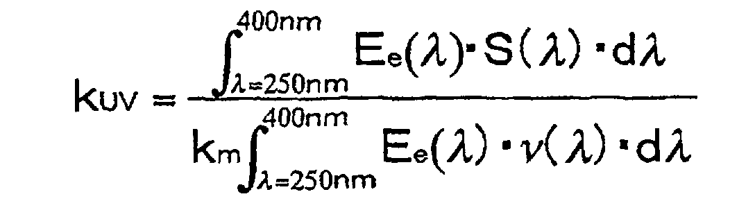
- Ee(λ):
- spectral distribution of radiant flux [W]
- ν (λ):
- spectral luminous efficacy [l]
- λ :
- wavelength [nm]
- S(λ):
- spectral load function [l]
- km :
- optical radiant equivalent (= 683 [lm/W])
- Furthermore, the total luminous flux at the initial period of lighting operation of the lamp is preferably 2900 lm or more, more preferably 3000 lm or more. Furthermore, the luminous flux maintenance factor after 1000 hours of lighting operation is preferably 70 % or more, more preferably 75 % or more.
- Furthermore, in the discharge lamp of the present invention, the general color rendering index (Ra) is preferably 60 or more, more preferably 65 or more.
- In order to obtain such properties, it is preferable in the discharge lamp of the present invention that a mixture of sodium halide (NaX) and scandium halide (ScX3) is used as the metal halide to be sealed in the light-emitting
portion 1a. Furthermore, in this case, the weight ratio of NaX and ScX3 is preferably in the range: 1 < NaX / ScX3 < 20. Moreover, as the halide (X), I and Br preferably are used. Furthermore, as the inert gas, for example, xenon is preferably used. - As shown in Table 1, sixteen types of outer tubes (Nos. 1 to 16) were produced by variously changing the contents of boron (wB), aluminum (wAl) and zirconium (wZr). Moreover, the outer tubes Nos. 1 to 16 contained 90 wt.% or more of silicon dioxide.
- Discharge lamps having the same structure as FIG. 1 were produced by using the above-produced outer tubes. Silica glass containing 99.98 wt.% silicon dioxide and having a softening temperature of 1683 °C was used for an arc tube. 16 mg of NaI, 4 mg of ScI3, 50mg of mercury and 7 atm of xenon gas were filled in the light-emitting portion. Moreover, the light-emitting portion had a content volume of 0.025cc and an arc length of 4.2mm.
- The arc tube was inserted into the outer tube, and then the outer tube and the arc tube were fused to each other, thus forming a discharge lamp. The fusing temperature was as low as possible in the range capable of softening the outer tube to be used. The produced discharge lamps were visually observed for the deformation of the arc tube. The results are shown in Table 1. In Table 1, A indicates that the arc tube was not deformed; B indicates that the arc tube was slightly deformed; and C indicates that the arc tube is greatly deformed.
Outer tube No. Content of additives in the outer tube [wt.%] Deformation of the arc tube wB wAl WZr WB + 2wAl + 5w Zr1 0.12 0 0 0.12 A 2 3.00 0 0 3.00 A 3 0.08 0.02 0 0.12 A 4 0.04 0.05 0 0.14 A 5 3.00 1.00 0 5.00 A 6 0.07 0 0.01 0.12 A 7 7.00 0 1.00 12.00 A 8 0.05 0.01 0.01 0.12 A 9 0.90 0.10 0.10 1.60 A 10 0.94 0.26 0.07 1.81 A 11 2.96 0.45 0.32 5.46 A 12 5.00 1.00 1.00 12.00 A 13 0.01 0 0 0.10 B 14 0.05 0.02 0 0.09 B 15 0.05 0 0.01 0.10 B 16 0 0 0 0 C - As shown in Table 1, when the outer tubes Nos. 1 to 12 were used, the arc tubes were not deformed. When the outer tubes Nos. 13 to 15 were used, the arc tubes were slightly deformed. On the other hand, when the outer tube No. 16 without containing boron, aluminum or zirconium was used, the arc tube was greatly deformed.
- Discharge lamps were produced using the same arc tubes and outer tubes (Nos. 1 to 16) as Example 1 and by changing the distance between the inner face of the outer tube and the outer face of the arc tube (the distance shown by D in FIG. 1). The thus produced discharge lamps were observed visually for the deformation of the outer tube after 1000 hours of lighting operation with 35 W electric power. The results are shown in Table 2. In Table 2, A indicates that the outer tube was not deformed, and B indicates that the outer tube was deformed.
Outer tube No. Distance between the outer tube and the arc tube D[mm] 0.01 0.02 0.05 0.10 1 A A A A 2 B B A A 3 A A A A 4 A A A A 5 B B A A 6 A A A A 7 B B B A 8 A A A A 9 B A A A 10 B A A A 11 B B A A 12 B B B A 13 A A A A 14 A A A A 15 A A A A 16 A A A A - As shown in Table 2, when (wB + 2wAl + 5wZr)/D ≦ 120 was satisfied, the deformation of the outer tube was not observed. On the other hand, when (wB + 2wAl + 5wzr)/D > 120 was satisfied, the deformation of the outer tube was observed.
- Discharge lamps were produced by using the same arc tubes and the outer tubes (Nos. 1 to 16) as Example 1 and by changing the shortest distance between the tip of the electrode and the fused portion of the arc tube and the outer tube (the distance shown by L in FIG. 1). The produced discharge lamps were observed visually for the deformation of the outer tube after 1000 hours of lighting operation with 35 W electric power. The results are shown in Table 3. In Table 3, A indicates that the fused portion was not deformed and B indicates that the fused portion was deformed.
Outer tube No. Distance between the fused portion of the outer tube and the arc tube and the electrode L[mm] 0.1 1.0 0.5 10.0 1 A A A A 2 B B B A 3 A A A A 4 B A A A 5 B B B A 6 A A A A 7 B B B A 8 A A A A 9 B B A A 10 B B A A 11 B B B A 12 B B B A 13 A A A A 14 A A A A 15 A A A A 16 A A A A - As shown in Table 3, when the expression: (wB + 2wAl + 5wZr)/L ≦ 1.2 is satisfied, the deformation was not observed in the fused portion of the outer tube and the arc tube. On the other hand, when the expression: (wB + 2wAl + 5wZr)/L > 1.2 is satisfied, the deformation was observed in the fused portion.
- Seven types of outer tubes (Nos. 17 to 23) were produced by using silica glass containing boron, aluminum and zirconium and by variously changing the contents of potassium (wK) and barium (wBa), as shown in Table 4. Moreover, the outer tubes (No. 17 to 23) contained 90 wt.% or more of silicon dioxide.
- By using the thus produced outer tubes, discharge lamps having the same structure as FIG. 1 were produced. As the arc tube, the same arc tube as Example 1 was used. The arc tube was inserted into the outer tube, and then the outer tube and the arc tube were fused to each other, thus forming a discharge lamp. The fusing temperature was made to be as low as possible in the range capable of softening the outer tube to be used. The produced discharge lamps were observed visually for devitrification of the outer tubes after 1000 hours of lighting operation with 35 W electric power. The results are shown in Table 4. In Table 4, A indicates that the devitrification of the outer tube was not observed and B indicates that the devitrification of the outer tube was observed.
Outer tube No. Content of additives in the outer tube [wt.%] Devitrification of the outer tube wB wAl wZr wK wBa 17 1.00 0.30 0.07 0 0 A 18 1.00 0.30 0.07 0.10 0 A 19 1.00 0.30 0.07 0 0.10 A 20 1.00 0.30 0.07 0.02 0.08 A 21 1.00 0.30 0.07 0.12 0 B 22 1.00 0.30 0.07 0 0.15 B 23 1.00 0.30 0.07 0.08 0.04 B - As shown in Table 4, when the outer tubes Nos. 17 to 20 were used, the devitrification of the outer tubes were not observed. On the other hand, when the outer tubes No. 21 to 23 were used, the devitrification of the outer tube was observed.
- Fourteen types of outer tubes (Nos. 24 to 37) were produced by using silica glass containing boron, aluminum and zirconium and by variously changing the contents of cerium (wCe), titanium (wTi), iron (wFe), praseodymium (wPr) and europium (wEu), as shown in Table 5. Moreover, the outer tubes No. 24 to 37 contained 90 wt.% or more of silicon dioxide.
- By using the thus produced outer tubes, discharge lamps having the same structure as FIG. 1 were produced. As the arc tube, the same arc tube as Example 1 was used. The arc tube was inserted into the outer tube, and then the outer tube and arc tube were fused to each other, thus forming a discharge lamp. When the produced discharge lamps were lighted up with 35 W electric power, ultraviolet rays radiant quantities (kUV) and the total luminous flux at the initial period of lighting operation were examined. The results are shown in Table 5.
Outer tube No Content of additives in the outer tube [wt.%] KUV [10-5 W/lm] Total luminous flux [lm] wB wAl wZr wCe wTi wFe wPr wEu 24 0.90 0.20 0.01 0.01 0 0 0 0 1.98 3250 25 0.90 0.20 0.01 0 0.01 0 0 0 1.85 3240 26 0.90 0.20 0.01 0 0 0.01 0 0 1.95 3270 27 0.90 0.20 0.01 0 0 0 0.01 0 1.76 3240 28 0.90 0.20 0.01 0 0 0 0 0.01 1.88 3260 29 0.90 0.20 0.01 1.00 0 0 0 0 0.07 3100 30 0.90 0.20 0.01 0 1.00 0 0 0 0.11 3080 31 0.90 0.20 0.01 0 0 1.00 0 0 0.03 3010 32 0.90 0.20 0.01 0 0 0 1.00 0 0.11 3040 33 0.90 0.20 0.01 0 0 0 0 1.00 0.23 3030 34 0.90 0.20 0.01 3.00 0 0 0 0 0.03 2840 35 0.90 0.20 0.01 0 3.00 0 0 0 0.04 2860 36 0.90 0.20 0.01 0 0 3.00 0 0 0.02 2760 37 0.90 0.20 0.01 0 0 0 0 0 2.25 3260 - As shown in Table 5, when the outer tubes Nos. 24 to 36 containing cerium, titanium, iron, praseodymium or eurogium were used, kUV was lower by about 10 % or more than the case where the outer tube No. 37 without containing the above-mentioned elements was used. Furthermore, when the outer tubes Nos. 24 to 33 containing less than 1 wt.% of cerium, titanium, iron, praseodymium and europium were used, high total luminous flux could be obtained.
Claims (18)
- A discharge lamp comprisingwherein said outer tube contains silicon dioxide as a main component and further contains boron.an arc tube having a light-emitting portion provided with a pair of electrodes andan outer tube enveloping said light-emitting portion and being at least partly fused to said arc tube,
- The discharge lamp according to claim 1, wherein said outer tube contains 0.12 wt.% or more of boron.
- The discharge lamp according to claim 1, satisfying
- The discharge lamp according to claim 1, satisfying
- The discharge lamp according to claim 1, wherein said outer tube contains 90 to 99.88 wt.% of silicon dioxide.
- The discharge lamp according to claim 1, wherein said outer tube contains no more than 0.1 wt.% of at least one element selected from the group consisting of lithium, sodium, potassium, rubidium, cesium, beryllium, magnesium, calcium, strontium and barium.
- The discharge lamp according to claim 1, wherein said outer tube further comprises at least one element selected from the group consisting of cerium, titanium, iron, praseodymium and europium.
- The discharge lamp according to claim 7, wherein the content of at least one element selected from the group consisting of cerium, titanium, iron, praseodymium and europium in said outer tube is 0.01 to 1 wt. %.
- The discharge lamp according to claim 1, satisfying
- A discharge lamp comprisingwherein said outer tube contains silicon dioxide as a main component and further contains at least one selected from aluminum and zirconium together with boron.an arc tube having a light-emitting portion provided with a pair of electrodes andan outer tube enveloping said light-emitting portion and being at least partly fused to said arc tube,
- The discharge lamp according to claim 10, satisfying
- The discharge lamp according to claim 10, satisfying
- The discharge lamp according to claim 10, satisfying
- The discharge lamp according to claim 10, wherein said outer tube contains 90 to 99.88 wt. % of silicon dioxide.
- The discharge lamp according to claim 10, wherein said outer tube contains no more than 0.1 wt.% of at least one element selected from the group consisting of lithium, sodium, potassium, rubidium, cesium, beryllium, magnesium, calcium, strontium and barium.
- The discharge lamp according to claim 10, wherein said outer tube further comprises at least one element selected from the group consisting of cerium, titanium, iron, praseodymium and europium.
- The discharge lamp according to claim 16, wherein the content of at least one element selected from the group consisting of cerium, titanium, iron, praseodymium and europium in said outer tube is 0.01 to 1 wt. %.
- The discharge lamp according to claim 10, satisfying
Applications Claiming Priority (4)
| Application Number | Priority Date | Filing Date | Title |
|---|---|---|---|
| JP16492298 | 1998-06-12 | ||
| JP16492298 | 1998-06-12 | ||
| JP33064698 | 1998-11-20 | ||
| JP33064698 | 1998-11-20 |
Publications (4)
| Publication Number | Publication Date |
|---|---|
| EP0964431A2 EP0964431A2 (en) | 1999-12-15 |
| EP0964431A3 EP0964431A3 (en) | 2000-03-22 |
| EP0964431B1 true EP0964431B1 (en) | 2002-01-23 |
| EP0964431B2 EP0964431B2 (en) | 2007-04-04 |
Family
ID=26489850
Family Applications (1)
| Application Number | Title | Priority Date | Filing Date |
|---|---|---|---|
| EP99110857A Expired - Lifetime EP0964431B2 (en) | 1998-06-12 | 1999-06-07 | Discharge lamp |
Country Status (5)
| Country | Link |
|---|---|
| US (1) | US6429577B1 (en) |
| EP (1) | EP0964431B2 (en) |
| CN (1) | CN1154141C (en) |
| DE (1) | DE69900804T3 (en) |
| ID (1) | ID23586A (en) |
Families Citing this family (12)
| Publication number | Priority date | Publication date | Assignee | Title |
|---|---|---|---|---|
| JP3777088B2 (en) * | 2000-11-24 | 2006-05-24 | 株式会社小糸製作所 | Arc tube for discharge lamp and manufacturing method thereof |
| TWI293947B (en) * | 2001-03-26 | 2008-03-01 | Tosoh Corp | |
| JP3916887B2 (en) * | 2001-06-05 | 2007-05-23 | 株式会社小糸製作所 | Lighting device |
| DE10141961A1 (en) * | 2001-08-28 | 2003-03-20 | Philips Corp Intellectual Pty | Discharge lamp and outer bulb therefor |
| KR100416381B1 (en) * | 2002-07-06 | 2004-01-31 | 김홍길 | Discharge lamp for a vehicle |
| DE10242203A1 (en) | 2002-09-10 | 2004-03-18 | Philips Intellectual Property & Standards Gmbh | High pressure discharge lamp for vehicle headlamps, comprises an inner bulb with a discharge chamber having an ionizable filling made from a noble gas, mercury and a metal halide mixture |
| KR20050088384A (en) * | 2002-12-17 | 2005-09-05 | 코닌클리즈케 필립스 일렉트로닉스 엔.브이. | High-pressure discharge lamp |
| ATE358328T1 (en) * | 2002-12-17 | 2007-04-15 | Koninkl Philips Electronics Nv | HIGH PRESSURE DISCHARGE LAMP |
| WO2006038148A1 (en) * | 2004-10-04 | 2006-04-13 | Philips Intellectual Property & Standards Gmbh | Quartz glass lamp with a defined ratio of aluminium and europium |
| CN1331003C (en) * | 2004-10-25 | 2007-08-08 | 罗筱泠 | Projection lamp bulb and projection lamp using said bulb |
| DE102005020344A1 (en) * | 2005-05-02 | 2006-11-09 | Patent-Treuhand-Gesellschaft für elektrische Glühlampen mbH | Electric lamp with outer bulb |
| DE102005035779A1 (en) * | 2005-07-29 | 2007-02-01 | Patent-Treuhand-Gesellschaft für elektrische Glühlampen mbH | Electrical lamp with outer bulb and production process has sealed long inner bulb with a light and outer bulb having narrowed neck section |
Family Cites Families (16)
| Publication number | Priority date | Publication date | Assignee | Title |
|---|---|---|---|---|
| JPH0719562B2 (en) * | 1988-02-23 | 1995-03-06 | エヌ・ベー・フィリップス・フルーイランペンファブリケン | Light |
| US4949003A (en) * | 1988-12-21 | 1990-08-14 | Gte Products Corporation | Oxygen protected electric lamp |
| US5196759B1 (en) | 1992-02-28 | 1996-09-24 | Gen Electric | High temperature lamps having UV absorbing quartz envelope |
| US5569979A (en) | 1992-02-28 | 1996-10-29 | General Electric Company | UV absorbing fused quartz and its use for lamp envelopes |
| TW226472B (en) † | 1992-06-01 | 1994-07-11 | Gen Electric | |
| DE4241152A1 (en) * | 1992-12-07 | 1994-06-09 | Patent Treuhand Ges Fuer Elektrische Gluehlampen Mbh | Doped quartz glass and objects made from it |
| CA2119336A1 (en) * | 1993-03-19 | 1994-09-20 | Edward H. Nortrup | Metal halide arc lamp having glass containment shroud |
| DE4317369A1 (en) † | 1993-05-25 | 1994-12-01 | Patent Treuhand Ges Fuer Elektrische Gluehlampen Mbh | High-pressure discharge lamp and manufacturing method for a high-pressure discharge lamp |
| US5631522A (en) | 1995-05-09 | 1997-05-20 | General Electric Company | Low sodium permeability glass |
| US5391523A (en) | 1993-10-27 | 1995-02-21 | Marlor; Richard C. | Electric lamp with lead free glass |
| BE1007870A3 (en) | 1993-12-14 | 1995-11-07 | Philips Electronics Nv | Electric lamp. |
| US5594294A (en) * | 1994-10-31 | 1997-01-14 | General Electric Company | Lamp assembly with a resilient retaining lamp mount structure |
| ES2121630T3 (en) * | 1994-11-10 | 1998-12-01 | Koninkl Philips Electronics Nv | ELECTRIC LAMP. |
| US5552665A (en) * | 1994-12-29 | 1996-09-03 | Philips Electronics North America Corporation | Electric lamp having an undercoat for increasing the light output of a luminescent layer |
| US5528107A (en) * | 1995-03-31 | 1996-06-18 | Osram Sylvania Inc | Lead and arsenic free, solarization resistant glass |
| US5719463A (en) * | 1996-06-03 | 1998-02-17 | General Electric Company | Retaining spring and stop means for lamp mount |
-
1999
- 1999-06-07 US US09/326,951 patent/US6429577B1/en not_active Expired - Lifetime
- 1999-06-07 DE DE69900804T patent/DE69900804T3/en not_active Expired - Fee Related
- 1999-06-07 EP EP99110857A patent/EP0964431B2/en not_active Expired - Lifetime
- 1999-06-10 ID IDP990545D patent/ID23586A/en unknown
- 1999-06-11 CN CNB991084438A patent/CN1154141C/en not_active Expired - Fee Related
Also Published As
| Publication number | Publication date |
|---|---|
| EP0964431A3 (en) | 2000-03-22 |
| DE69900804T2 (en) | 2002-11-14 |
| US6429577B1 (en) | 2002-08-06 |
| ID23586A (en) | 2000-05-04 |
| EP0964431A2 (en) | 1999-12-15 |
| DE69900804D1 (en) | 2002-03-14 |
| CN1154141C (en) | 2004-06-16 |
| DE69900804T3 (en) | 2007-07-12 |
| CN1239314A (en) | 1999-12-22 |
| EP0964431B2 (en) | 2007-04-04 |
Similar Documents
| Publication | Publication Date | Title |
|---|---|---|
| US5572091A (en) | Quartz glass with reduced ultraviolet radiation transmissivity, and electrical discharge lamp using such glass | |
| USRE38807E1 (en) | High pressure discharge lamp, with tungsten electrode and lighting optical apparatus and image display system using the same | |
| US7098596B2 (en) | Mercury-free arc tube for discharge lamp unit | |
| KR100515253B1 (en) | High-Pressure Mercury Lamp | |
| EP0964431B1 (en) | Discharge lamp | |
| US5726532A (en) | High-pressure discharge lamp and process for producing it | |
| KR20020007193A (en) | Mercury-free metal halide lamp | |
| US20160254135A1 (en) | Discharge lamp with optimized salt filling | |
| JPH06203811A (en) | Lamp including tungsten - halogen light source | |
| EP0459786A2 (en) | Metal halide lamp apparatus | |
| EP1310984B1 (en) | High pressure mercury lamp, illumination device using the high-pressure mercury lamp, and image display apparatus using the illumination device | |
| KR100343483B1 (en) | Electric lamp | |
| US5635796A (en) | High-pressure discharge lamp including halides of tantalum and dysprosium | |
| EP0901151B1 (en) | High-pressure mercury vapor discharge lamp | |
| JP2005123112A (en) | Metal halide lamp and lighting system | |
| US20060279220A1 (en) | Electric lamp comprising aluminum oxide and cerium oxide | |
| JP3436186B2 (en) | Discharge lamp | |
| JP3307272B2 (en) | Discharge lamp and video projector using this discharge lamp | |
| JP4082178B2 (en) | Ceramic metal halide lamp | |
| JPH06260138A (en) | Metal halide lamp | |
| JPH06168701A (en) | Metal halide lamp | |
| JPH0864171A (en) | Metal halide lamp | |
| JPH04184859A (en) | Metal halide lamp | |
| JPH0494053A (en) | Metal halide lamp |
Legal Events
| Date | Code | Title | Description |
|---|---|---|---|
| PUAI | Public reference made under article 153(3) epc to a published international application that has entered the european phase |
Free format text: ORIGINAL CODE: 0009012 |
|
| AK | Designated contracting states |
Kind code of ref document: A2 Designated state(s): DE FR |
|
| AX | Request for extension of the european patent |
Free format text: AL;LT;LV;MK;RO;SI |
|
| PUAL | Search report despatched |
Free format text: ORIGINAL CODE: 0009013 |
|
| RIC1 | Information provided on ipc code assigned before grant |
Free format text: 7C 03C 3/091 A, 7H 01J 61/34 B |
|
| AK | Designated contracting states |
Kind code of ref document: A3 Designated state(s): AT BE CH CY DE DK ES FI FR GB GR IE IT LI LU MC NL PT SE |
|
| AX | Request for extension of the european patent |
Free format text: AL;LT;LV;MK;RO;SI |
|
| 17P | Request for examination filed |
Effective date: 20000311 |
|
| 17Q | First examination report despatched |
Effective date: 20000922 |
|
| AKX | Designation fees paid |
Free format text: DE FR |
|
| GRAG | Despatch of communication of intention to grant |
Free format text: ORIGINAL CODE: EPIDOS AGRA |
|
| GRAG | Despatch of communication of intention to grant |
Free format text: ORIGINAL CODE: EPIDOS AGRA |
|
| GRAH | Despatch of communication of intention to grant a patent |
Free format text: ORIGINAL CODE: EPIDOS IGRA |
|
| RIN1 | Information on inventor provided before grant (corrected) |
Inventor name: SAITOH, TAKESHI, C/O MATSUSHITA ELECTRONICS CORP. Inventor name: TANAKA, KAZUHISA, C/O MATSUSHITA ELECTRONICS CORP Inventor name: KIRYU, HIDEAKI |
|
| GRAH | Despatch of communication of intention to grant a patent |
Free format text: ORIGINAL CODE: EPIDOS IGRA |
|
| RAP1 | Party data changed (applicant data changed or rights of an application transferred) |
Owner name: MATSUSHITA ELECTRIC INDUSTRIAL CO., LTD. |
|
| RIN1 | Information on inventor provided before grant (corrected) |
Inventor name: SAITOH, TAKESHI, Inventor name: TANAKA, KAZUHISA, C/O MATSUSHITA ELECTRONICS CORP Inventor name: KIRYU, HIDEAKI |
|
| GRAA | (expected) grant |
Free format text: ORIGINAL CODE: 0009210 |
|
| AK | Designated contracting states |
Kind code of ref document: B1 Designated state(s): DE FR |
|
| REF | Corresponds to: |
Ref document number: 69900804 Country of ref document: DE Date of ref document: 20020314 |
|
| ET | Fr: translation filed | ||
| PLBQ | Unpublished change to opponent data |
Free format text: ORIGINAL CODE: EPIDOS OPPO |
|
| PLBI | Opposition filed |
Free format text: ORIGINAL CODE: 0009260 |
|
| PLBQ | Unpublished change to opponent data |
Free format text: ORIGINAL CODE: EPIDOS OPPO |
|
| PLAB | Opposition data, opponent's data or that of the opponent's representative modified |
Free format text: ORIGINAL CODE: 0009299OPPO |
|
| PLBF | Reply of patent proprietor to notice(s) of opposition |
Free format text: ORIGINAL CODE: EPIDOS OBSO |
|
| 26 | Opposition filed |
Opponent name: OSRAM GMBH Effective date: 20021022 |
|
| R26 | Opposition filed (corrected) |
Opponent name: OSRAM GMBH Effective date: 20021022 |
|
| PLBF | Reply of patent proprietor to notice(s) of opposition |
Free format text: ORIGINAL CODE: EPIDOS OBSO |
|
| PLBF | Reply of patent proprietor to notice(s) of opposition |
Free format text: ORIGINAL CODE: EPIDOS OBSO |
|
| PLAX | Notice of opposition and request to file observation + time limit sent |
Free format text: ORIGINAL CODE: EPIDOSNOBS2 |
|
| PLAX | Notice of opposition and request to file observation + time limit sent |
Free format text: ORIGINAL CODE: EPIDOSNOBS2 |
|
| PLBB | Reply of patent proprietor to notice(s) of opposition received |
Free format text: ORIGINAL CODE: EPIDOSNOBS3 |
|
| RAP2 | Party data changed (patent owner data changed or rights of a patent transferred) |
Owner name: MATSUSHITA ELECTRIC INDUSTRIAL CO., LTD. |
|
| PUAH | Patent maintained in amended form |
Free format text: ORIGINAL CODE: 0009272 |
|
| STAA | Information on the status of an ep patent application or granted ep patent |
Free format text: STATUS: PATENT MAINTAINED AS AMENDED |
|
| 27A | Patent maintained in amended form |
Effective date: 20070404 |
|
| AK | Designated contracting states |
Kind code of ref document: B2 Designated state(s): DE FR |
|
| ET3 | Fr: translation filed ** decision concerning opposition | ||
| PGFP | Annual fee paid to national office [announced via postgrant information from national office to epo] |
Ref country code: DE Payment date: 20080612 Year of fee payment: 10 |
|
| PGFP | Annual fee paid to national office [announced via postgrant information from national office to epo] |
Ref country code: FR Payment date: 20080617 Year of fee payment: 10 |
|
| REG | Reference to a national code |
Ref country code: FR Ref legal event code: ST Effective date: 20100226 |
|
| PG25 | Lapsed in a contracting state [announced via postgrant information from national office to epo] |
Ref country code: FR Free format text: LAPSE BECAUSE OF NON-PAYMENT OF DUE FEES Effective date: 20090630 |
|
| PG25 | Lapsed in a contracting state [announced via postgrant information from national office to epo] |
Ref country code: DE Free format text: LAPSE BECAUSE OF NON-PAYMENT OF DUE FEES Effective date: 20100101 |