EP0963536B1 - Oil return from evaporator to compressor in a refrigeration system - Google Patents
Oil return from evaporator to compressor in a refrigeration system Download PDFInfo
- Publication number
- EP0963536B1 EP0963536B1 EP98902644A EP98902644A EP0963536B1 EP 0963536 B1 EP0963536 B1 EP 0963536B1 EP 98902644 A EP98902644 A EP 98902644A EP 98902644 A EP98902644 A EP 98902644A EP 0963536 B1 EP0963536 B1 EP 0963536B1
- Authority
- EP
- European Patent Office
- Prior art keywords
- mixture
- compressor
- evaporator
- pressure
- refrigeration system
- Prior art date
- Legal status (The legal status is an assumption and is not a legal conclusion. Google has not performed a legal analysis and makes no representation as to the accuracy of the status listed.)
- Expired - Lifetime
Links
- 238000005057 refrigeration Methods 0.000 title claims description 91
- 239000000203 mixture Substances 0.000 claims description 103
- 239000003507 refrigerant Substances 0.000 claims description 84
- 239000000314 lubricant Substances 0.000 claims description 62
- 239000007788 liquid Substances 0.000 claims description 48
- 238000000034 method Methods 0.000 claims description 45
- 239000011552 falling film Substances 0.000 claims description 16
- 238000012546 transfer Methods 0.000 claims description 13
- 230000007423 decrease Effects 0.000 claims description 8
- 238000009826 distribution Methods 0.000 claims description 6
- 238000004891 communication Methods 0.000 claims description 5
- 238000011144 upstream manufacturing Methods 0.000 claims description 5
- 239000012141 concentrate Substances 0.000 claims description 3
- 230000037361 pathway Effects 0.000 claims description 2
- 238000011176 pooling Methods 0.000 claims description 2
- 239000003921 oil Substances 0.000 description 124
- 230000008569 process Effects 0.000 description 20
- 230000003071 parasitic effect Effects 0.000 description 12
- 230000000694 effects Effects 0.000 description 7
- 238000012423 maintenance Methods 0.000 description 6
- 238000011010 flushing procedure Methods 0.000 description 5
- 230000006835 compression Effects 0.000 description 4
- 238000007906 compression Methods 0.000 description 4
- 239000012530 fluid Substances 0.000 description 4
- 239000011555 saturated liquid Substances 0.000 description 4
- 239000006260 foam Substances 0.000 description 3
- XLYOFNOQVPJJNP-UHFFFAOYSA-N water Substances O XLYOFNOQVPJJNP-UHFFFAOYSA-N 0.000 description 3
- 230000002411 adverse Effects 0.000 description 2
- 230000015556 catabolic process Effects 0.000 description 2
- 238000013461 design Methods 0.000 description 2
- 230000006870 function Effects 0.000 description 2
- 238000002347 injection Methods 0.000 description 2
- 239000007924 injection Substances 0.000 description 2
- 230000007246 mechanism Effects 0.000 description 2
- 230000002829 reductive effect Effects 0.000 description 2
- 230000008439 repair process Effects 0.000 description 2
- 241000237858 Gastropoda Species 0.000 description 1
- 238000013459 approach Methods 0.000 description 1
- 230000008859 change Effects 0.000 description 1
- 239000010725 compressor oil Substances 0.000 description 1
- 239000000470 constituent Substances 0.000 description 1
- 125000004122 cyclic group Chemical group 0.000 description 1
- 230000003247 decreasing effect Effects 0.000 description 1
- 230000001627 detrimental effect Effects 0.000 description 1
- 239000010408 film Substances 0.000 description 1
- 230000005484 gravity Effects 0.000 description 1
- 235000003642 hunger Nutrition 0.000 description 1
- 230000002706 hydrostatic effect Effects 0.000 description 1
- 230000000670 limiting effect Effects 0.000 description 1
- 239000007791 liquid phase Substances 0.000 description 1
- 230000001050 lubricating effect Effects 0.000 description 1
- 238000005461 lubrication Methods 0.000 description 1
- 230000013011 mating Effects 0.000 description 1
- 238000012986 modification Methods 0.000 description 1
- 230000004048 modification Effects 0.000 description 1
- 238000012544 monitoring process Methods 0.000 description 1
- 239000012071 phase Substances 0.000 description 1
- 238000005086 pumping Methods 0.000 description 1
- 238000011084 recovery Methods 0.000 description 1
- 230000002441 reversible effect Effects 0.000 description 1
- 239000000565 sealant Substances 0.000 description 1
- 230000037351 starvation Effects 0.000 description 1
- 230000004083 survival effect Effects 0.000 description 1
- 238000009827 uniform distribution Methods 0.000 description 1
- 238000009834 vaporization Methods 0.000 description 1
- 230000008016 vaporization Effects 0.000 description 1
Images


Classifications
-
- F—MECHANICAL ENGINEERING; LIGHTING; HEATING; WEAPONS; BLASTING
- F25—REFRIGERATION OR COOLING; COMBINED HEATING AND REFRIGERATION SYSTEMS; HEAT PUMP SYSTEMS; MANUFACTURE OR STORAGE OF ICE; LIQUEFACTION SOLIDIFICATION OF GASES
- F25B—REFRIGERATION MACHINES, PLANTS OR SYSTEMS; COMBINED HEATING AND REFRIGERATION SYSTEMS; HEAT PUMP SYSTEMS
- F25B1/00—Compression machines, plants or systems with non-reversible cycle
- F25B1/04—Compression machines, plants or systems with non-reversible cycle with compressor of rotary type
- F25B1/047—Compression machines, plants or systems with non-reversible cycle with compressor of rotary type of screw type
-
- F—MECHANICAL ENGINEERING; LIGHTING; HEATING; WEAPONS; BLASTING
- F25—REFRIGERATION OR COOLING; COMBINED HEATING AND REFRIGERATION SYSTEMS; HEAT PUMP SYSTEMS; MANUFACTURE OR STORAGE OF ICE; LIQUEFACTION SOLIDIFICATION OF GASES
- F25B—REFRIGERATION MACHINES, PLANTS OR SYSTEMS; COMBINED HEATING AND REFRIGERATION SYSTEMS; HEAT PUMP SYSTEMS
- F25B43/00—Arrangements for separating or purifying gases or liquids; Arrangements for vaporising the residuum of liquid refrigerant, e.g. by heat
- F25B43/02—Arrangements for separating or purifying gases or liquids; Arrangements for vaporising the residuum of liquid refrigerant, e.g. by heat for separating lubricants from the refrigerant
-
- F—MECHANICAL ENGINEERING; LIGHTING; HEATING; WEAPONS; BLASTING
- F25—REFRIGERATION OR COOLING; COMBINED HEATING AND REFRIGERATION SYSTEMS; HEAT PUMP SYSTEMS; MANUFACTURE OR STORAGE OF ICE; LIQUEFACTION SOLIDIFICATION OF GASES
- F25B—REFRIGERATION MACHINES, PLANTS OR SYSTEMS; COMBINED HEATING AND REFRIGERATION SYSTEMS; HEAT PUMP SYSTEMS
- F25B31/00—Compressor arrangements
- F25B31/002—Lubrication
- F25B31/004—Lubrication oil recirculating arrangements
-
- F—MECHANICAL ENGINEERING; LIGHTING; HEATING; WEAPONS; BLASTING
- F25—REFRIGERATION OR COOLING; COMBINED HEATING AND REFRIGERATION SYSTEMS; HEAT PUMP SYSTEMS; MANUFACTURE OR STORAGE OF ICE; LIQUEFACTION SOLIDIFICATION OF GASES
- F25B—REFRIGERATION MACHINES, PLANTS OR SYSTEMS; COMBINED HEATING AND REFRIGERATION SYSTEMS; HEAT PUMP SYSTEMS
- F25B39/00—Evaporators; Condensers
- F25B39/02—Evaporators
- F25B39/028—Evaporators having distributing means
-
- F—MECHANICAL ENGINEERING; LIGHTING; HEATING; WEAPONS; BLASTING
- F25—REFRIGERATION OR COOLING; COMBINED HEATING AND REFRIGERATION SYSTEMS; HEAT PUMP SYSTEMS; MANUFACTURE OR STORAGE OF ICE; LIQUEFACTION SOLIDIFICATION OF GASES
- F25B—REFRIGERATION MACHINES, PLANTS OR SYSTEMS; COMBINED HEATING AND REFRIGERATION SYSTEMS; HEAT PUMP SYSTEMS
- F25B2339/00—Details of evaporators; Details of condensers
- F25B2339/02—Details of evaporators
- F25B2339/024—Evaporators with refrigerant in a vessel in which is situated a heat exchanger
- F25B2339/0242—Evaporators with refrigerant in a vessel in which is situated a heat exchanger having tubular elements
-
- F—MECHANICAL ENGINEERING; LIGHTING; HEATING; WEAPONS; BLASTING
- F25—REFRIGERATION OR COOLING; COMBINED HEATING AND REFRIGERATION SYSTEMS; HEAT PUMP SYSTEMS; MANUFACTURE OR STORAGE OF ICE; LIQUEFACTION SOLIDIFICATION OF GASES
- F25B—REFRIGERATION MACHINES, PLANTS OR SYSTEMS; COMBINED HEATING AND REFRIGERATION SYSTEMS; HEAT PUMP SYSTEMS
- F25B2700/00—Sensing or detecting of parameters; Sensors therefor
- F25B2700/19—Pressures
- F25B2700/195—Pressures of the condenser
-
- F—MECHANICAL ENGINEERING; LIGHTING; HEATING; WEAPONS; BLASTING
- F25—REFRIGERATION OR COOLING; COMBINED HEATING AND REFRIGERATION SYSTEMS; HEAT PUMP SYSTEMS; MANUFACTURE OR STORAGE OF ICE; LIQUEFACTION SOLIDIFICATION OF GASES
- F25B—REFRIGERATION MACHINES, PLANTS OR SYSTEMS; COMBINED HEATING AND REFRIGERATION SYSTEMS; HEAT PUMP SYSTEMS
- F25B2700/00—Sensing or detecting of parameters; Sensors therefor
- F25B2700/19—Pressures
- F25B2700/197—Pressures of the evaporator
Definitions
- the present invention is directed to the return of oil, which is carried downstream and out of a refrigeration compressor in the discharge gas flow stream to the system evaporator, back to the compressor.
- An embodiment of the invention is directed to the cyclic return of oil from a falling film evaporator in a screw compressor-based refrigeration chiller system by the use of and in accordance with then-existing differential pressures within the system, all in a manner which minimizes the parasitic losses to system efficiency associated with the oil return process.
- Screw compressors have come to be used in refrigeration systems due to their ability to be part-loaded over a wide capacity range and in a continuous manner by use of a capacity control slide valve. In previous systems, unloading was most often in a stepwise fashion which is nowhere near as efficient as the load-matching made available over a continuous capacity range through the use of a screw compressor having slide valve capacity control.
- Screw compressors in operation, employ rotors which are disposed in a working chamber.
- Refrigerant gas at suction pressure enters the low pressure end of the compressor's working chamber and is enveloped in a compression pocket formed between the counter-rotating screw rotors and the wall of the working chamber in which they are disposed.
- the volume of such a compression pocket decreases and the pocket is circumferentially displaced to the high pressure end of the working chamber as the rotors rotate and mesh.
- the gas within such a pocket is compressed and heated by virtue of the decreasing volume in which it is contained until such time as the pocket comes into communication with a discharge port defined in the high pressure end of the working chamber.
- oil is injected into the working chamber of screw compressors (and therefore into the refrigerant gas being compressed) in relatively large quantities and for several reasons.
- injected oil acts to cool the refrigerant gas undergoing compression which, in turn, causes the rotors to run cooler. This allows for tighter tolerances between the rotors from the outset.
- Injected oil also acts as a lubricant.
- One of the two rotors in a twin screw compressor is typically driven by an external source such as an electric motor.
- the mating rotor is driven by virtue of its meshing relationship with the externally driven rotor.
- Injected oil prevents excessive wear between the driving and driven rotors. Oil is additionally delivered to various bearing surfaces within the compressor for their lubrication and is used to reduce compressor noise.
- oil injected into the working chamber of a screw compressor acts as a sealant between the edge and end surfaces of the individual screw rotors and between the rotors themselves and the walls of the working chamber in which they are disposed. There are no discrete seals between those elements and surfaces and absent the injection of oil, significant leakage paths would exist internal of the working chamber of a screw compressor which would be highly detrimental to compressor and overall system efficiency. In sum, oil injection both increases the efficiency and prolongs the life of a refrigeration screw compressor.
- Oil making its way into the working chamber of a screw compressor ends up, for the most part, being entrained in the form of atomized liquid droplets in the refrigerant gas undergoing compression therein.
- Such oil must be removed from the oil-rich refrigerant gas which discharged from the compressor in order to make it available for return to the compressor for the purposes enumerated above.
- compressor lubricant may comprise on the order of 10% by weight of the compressed refrigerant gas discharged from the compressor and despite the availability and use of 99.9% efficient oil separators, 0.1% of the lubricant available to a screw compressor is continuously carried out of the compressor-separator combination and into downstream components of the refrigeration system.
- Such lubricant typically makes its way to the low-side of the refrigeration system and concentrates in the system evaporator.
- the low-side of a refrigeration system is the portion of the system which is downstream of the system expansion valve but upstream of the compressor where relatively low pressures exist while the high-side of the system is generally downstream of the compressor but upstream of the system expansion valve where pressures are relatively much higher.
- eductors can impose anywhere from approximately a 1% to 2% penalty on system efficiency by their operation with the efficiency penalty being largest when the system operates at part load (which screw compressor-based systems often do). As such and in view of the fact that they may not operate to required levels of performance over the entire range of system operating conditions, eductors are not a viable candidate for use in refrigeration systems which employ screw compressors and falling film evaporators even though they are mechanically simple and are essentially maintenance free.
- One active rather than passive system and methodology for evaporator to compressor oil return in a refrigeration system involves the use of a so-called gas pump wherein the relatively large pressure differential between the high-side and low-side of the system is used to drive lubricant from the evaporator back to the compressor.
- a so-called gas pump wherein the relatively large pressure differential between the high-side and low-side of the system is used to drive lubricant from the evaporator back to the compressor.
- Exemplary of such a system is the one described in U.S. Patent 2,246,845 to Durden.
- Durden teaches a reciprocating compressor-based refrigeration system which makes use of an accumulator tank to store a lubricant-rich mixture received from the evaporator until such time as a separate container, incorporating a float mechanism, fills with the same lubricant-rich mixture. Filling of the float tank is indicative that the separate accumulator is likewise filled.
- the float When the float tank fills, the float lifts and contact is made in an electrical switch mechanism that energizes a solenoid-type valve which admits pressure from the system condenser to the accumulator. Condenser pressure then drives the lubricant-rich mixture out of the accumulator through a thermostatic expansion valve.
- the expansion valve controls the flow rate of the mixture into an oil rectifying tank and rectified lubricant is returned to the compressor suction line. Rectification is necessary in the Durden system to prevent the return of slugs of liquid to the compressor which, in the case of reciprocating compressor, is potentially damaging.
- Oil return in Durden occurs as a result of the filling of both the accumulator and float tank.
- the period of time during which the Durden accumulator empties is a function of the speed of the rectification process which, in turn, is controlled by the thermostatic expansion valve that restricts flow out of the accumulator in accordance with a temperature sensed in the lubricant return line downstream of the rectifier tank. Oil return apparently occurs in Durden without regard to the effect of the oil return process on system efficiency.
- the invention provides a refrigeration system comprising:
- the part of the system at a pressure greater than evaporator pressure may be the condenser, in which case said pressure which is greater than evaporator pressure is condenser pressure.
- the system may further comprise means for determining a pressure internal of said condenser; means for determining a pressure internal of said evaporator; and control means, said control means determining the period of time said mixture is exposed to condenser pressure in accordance with the differential pressure between said evaporator and said condenser.
- the means for returning may include a collection tank, said mixture passing from said evaporator into said collection tank, the portion of said mixture returned to said compressor by exposure to condenser pressure being returned from said collection tank.
- the means for returning may be arranged to return the mixture said mixture to said compressor in cycles, and the system further comprises means for sensing a parameter used to determine the load on the refrigeration system, the length of a return cycle being determined in accordance with said load on said refrigeration system.
- the mixture in said collection tank is exposed to refrigerant gas source from said condenser and said returning means is arranged such that exposure of said mixture to said refrigerant gas terminates generally coincident with the emptying of said collecting tank of said mixture so as to prevent the bypass of said evaporator by said gas sourced from said condenser other than to the extent necessary to empty said collection tank of said mixture.
- the compressor is a screw compressor and return of said mixture to said compressor is downstream of the suction line of said compressor, said mixture consisting primarily of liquid refrigerant.
- the evaporator is a falling film evaporator, refrigerant in its liquid state, refrigerant in its gaseous state and compressor lubricant is received by said evaporator from said metering device, and the system further comprises means for separating refrigerant in its gaseous state from refrigerant in its liquid state, said separating means delivering liquid refrigerant and compressor lubricant to the interior of said evaporator for distribution and heat transfer therein.
- the means for returning may be arranged to return said mixture to said compressor in cycles, the system further comprising sensing means for sensing a parameter used to determine the load on the refrigeration and the length of a cycle being determined in accordance with said load on said refrigeration system.
- the pressure greater than evaporator pressure may be condenser pressure and said mixture is returned to said compressor during each individual cycle for said period of time.
- the length of said cycles may decrease as the load on said refrigeration system decreases.
- the means for returning includes a collection tank, said mixture passing from said evaporators into said collection tank, the portion of said mixture returned to said compressor during a cycle being returned from said collection tank, said mixture in said collection tank being exposed to refrigerant gas sourced from said condenser, exposure of said mixture to said refrigerant gas sourced from said condenser terminating generally coincident with the emptying of said collection tank of said mixture so as to prevent the bypass of said evaporator by said gas sourced from said condenser other than to the extent necessary to empty said collection tank of said mixture.
- the system further comprises means for determining the load on said refrigeration system; means for determining condenser pressure; means for determining evaporator pressure; and means for controlling the return of said mixture to said compressor, the source of pressure for returning said mixture to said compressor being said condenser, said mixture being returned to said compressor for a predetermined period of time within a return cycle, said period of time being determined in accordance with the difference between evaporator pressure and condenser pressure.
- the system may further comprise means for distributing liquid refrigerant within said evaporator, the location in said evaporator to which said mixture is returned being within said means for distributing liquid refrigerant within said evaporator.
- the system may further comprise means for separating refrigerant in its gaseous state from refrigerant in its liquid state, said means for separating being disposed downstream of said metering device, upstream of said means for distributing and in flow communication with both.
- the invention also includes a method of returning lubricant carried out of a compressor in a refrigeration system in the stream of refrigerant gas discharged therefrom, where such lubricant tends to concentrate as a mixture of lubricant and refrigerant in the evaporator of said system, comprising the steps of:
- the return of said mixture to said compressor may occur in cycles and the method further comprise the step of determining the load on said refrigeration system, said exposing step occurring once in an individual one of said return cycles, the length of an individual return cycle being determined in accordance with the sensed load on said refrigeration system.
- the method may further comprise the step of directing said mixture to and collecting said mixture in a discrete housing, the portion of said mixture returned to said compressor during a return cycle being returned from said housing.
- the condenser may be the source of said high-side pressure.
- the mixture is preferably returned to said compressor in liquid form and downstream of the suction line of said compressor.
- the method may include collecting said mixture in a housing; providing a pathway between said housing and the evaporator; isolating the interior of said housing from the interior of said evaporator; and exposing said collected mixture to said high-side pressure, whereby said collected-mixture is driven back in part to said compressor and in part to a location in said evaporator.
- the step of exposing the collected mixture may comprise the step of exposing said collected mixture comprises the step of exposing said collected mixture to the pressure in the condenser of said system.
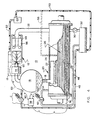
- refrigeration chiller system 10 includes a screw compressor 12 which discharges a refrigerant gas stream in which a significant amount of lubricant is entrained to an oil separator 14 in the form of atomized liquid droplets.
- Oil separator 14 is a high efficiency separator which permits only a relatively very small amount of lubricant received from the compressor (on the order of 0.1%) to escape and flow downstream to condenser 16. Separated oil is returned to the compressor via a return line 15, driven, in the preferred embodiment, by discharge pressure.
- Refrigerant gas condenses in condenser 16 and pools at the bottom thereof along with the lubricant which is carried into the condenser.
- Liquid refrigerant flows out of condenser 16 carrying such lubricant with it and passes through expansion valve 18.
- Expansion valve 18 is, in the preferred embodiment, an electronic expansion valve.
- the refrigerant-lubricant mixture next flows into evaporator 20 in the form of a two-phase mixture which consists primarily of a liquid phase.
- Evaporator 20 in the preferred embodiment, is a so-called falling film evaporator although the present invention likewise has application in systems employing so-called sprayed evaporators.
- Falling film evaporator 20 which can be in the nature of the one described in the '987 patent mentioned above, will have a vapor-liquid separator 22 associated with it.
- Separator 22 delivers liquid refrigerant to distribution device 24 and directs refrigerant vapor out of the evaporator through compressor suction line 25 back to compressor 10.
- Separator 22 may be disposed within evaporator 20 in the manner described in the '987 patent or it may be disposed as a separate component exterior of the evaporator.
- Distribution device 24 is preferably in close proximity to and immediately above the uppermost portion of tube bundle 26 within evaporator 20. As is noted in the '987 patent, a slight hydrostatic head is allowed to develop within the vapor-liquid separator. This permits the flow of saturated liquid out of the separator and into the distribution device without flashing which, in turn, promotes and enhances the uniform distribution of liquid refrigerant (and any lubricant entrained therein) to and over tube bundle 26 through which a heat transfer medium, such as water, flows.
- a heat transfer medium such as water
- the liquid pool at the bottom of the evaporator is of significantly less volume than the liquid pools in previous evaporators wherein the majority of the tube bundle, by design, is completely immersed in liquid refrigerant. As a result, the quantity of refrigerant used by the system can be significantly reduced.
- the oil concentration level in the evaporator pool is chosen to be maintained in the proximity of 8% due to the fact that at higher concentrations the lubricant in the mixture will tend to froth and foam and such foam will tend to blanket additional tubes in the tube bundle 26.
- the blanketing of additional tubes by lubricant foam reduces the ability of those tubes to transfer heat from the heat transfer medium flowing through them to the system refrigerant. An efficiency penalty therefore comes into play if, in the preferred embodiment, oil concentration in the liquid pool in the evaporator is permitted to exceed 8%.
- the lowest lubricant return rate that can be permitted to occur in order to maintain that lubricant concentration level in the evaporator is determined. Referring to Figure 1, it will be appreciated that if an 8% maximum concentration of lubricant in the liquid refrigerant pool in the bottom of the evaporator is established, the lowest lubricant return rate that can be permitted to occur is a relatively very low .46 gallons per minute (approximately 1.74 Litres per minute).
- lubricant return in the present invention is premised on a desire to approach the .46 gallon per minute (approximately 1.74 Litres per minutes) oil return rate within the confines and constraints of the apparatus and methodology used to achieve such return and in view of the fact that the lower the return rate can be maintained over the system operating range, the lower will be the resulting parasitic losses to system efficiency.
- thermosensor 34 senses the temperature of the saturated liquid refrigerant in condenser 16 while sensor 36 senses the temperature of the saturated liquid pooled at the bottom of evaporator 20.
- controller 38 converts the temperature of the saturated liquid refrigerant in condenser 16 and sensor 36 to the temperature of the saturated liquid pooled at the bottom of evaporator 20.
- Those temperatures are converted by controller 38 to condenser and evaporator-related pressures, their difference is calculated, and the fill solenoid 42 is caused to close and the drain solenoid 40 is caused to open for the period of time indicated in Figure 5.
- the use of sensed saturated liquid temperatures is convenient and comes at essentially no cost because these temperatures are already sensed and used for other control purposes in the context of the preferred refrigeration system.
- Opening of the drain solenoid during any given cycle causes collection tank 32 to empty and be “flushed” through filter 44 back to compressor 12 in an amount of time which, once again, varies in accordance with the then-existing pressure differential between the condenser and evaporator. That rate, however, remains low as do the efficiency penalties imposed by the oil return process. Further, the oil return process according to the apparatus and methodology of the present invention occurs without the need for components such as pumps, float valves, float tanks, electrical contacts or rectification apparatus, all of which come at significant expense, are subject to failure and wear and which too often need repair or maintenance.
- Conduit 52 opens into the interior of the housing 54 in which the compressor rotors and drive motor 56 are disposed, preferably downstream of the motor and upstream of the rotors.
- the fluid returned to the compressor is primarily in liquid form (some of the refrigerant portion of the fluid may be in gaseous form) and that the fluid returned to the compressor is returned downstream of the suction line 25 of compressor 10. Return of liquids to some compressors of other than the screw type can be fatal to survival of the compressor.
- controller 38 signals drain solenoid 40 to close and fill solenoid 42 to open.
- the closure of drain solenoid 40 isolates collection tank 32 from condenser pressure while the opening of fill solenoid 42 vents collection tank 32 to the interior of evaporator 20.
- the liquid pool at the bottom of evaporator 20 drains by force of gravity past check valve 30 into tank 32 until such time as the solenoids are next caused to reverse position so as to cause flushing of the contents of tank 32 back to compressor 12.
- Efficiency of the oil return method and apparatus of the present invention can still further be optimized in an enhanced version of the preferred embodiment by varying the length of each oil return cycle in accordance with the then-existing actual load on the refrigeration system.
- Oil return cycle times can be extended at low load conditions for the reason that the oil separators used in the refrigeration system of the present invention become even more efficient as the load on the system decreases. As such, not as great a percentage of oil escapes the oil separator and needs to be returned to the compressor.
- the position of compressor slide valve 60 is sensed and communicated to controller 38 via communications line 62 which is shown in phantom.
- the position of slide valve 60 is determinative of the capacity of compressor 12 and is, in turn, determinative of system capacity.
- Slide valve 60 is controlled so as to be positioned in accordance with the instantaneous demand for capacity or load on the refrigeration system. In that way, the chiller system "works" only as hard as it needs to in order to meet the then-existing refrigeration "load” on the system.
- the position of slide valve 60 is modulated to match the changing load.
- an indication of the instantaneous load on the system is made available and can be factored into the oil-return methodology. It is to be noted that other system parameters can be sensed, compared and used to determine the load on a refrigeration system at any given time, including evaporator entering and leaving water temperatures, evaporator water flow and that the use of any of them or combinations of any of them to assist in the oil return process are likewise contemplated hereby.
- the screw compressor employed in the chiller system of the preferred embodiment is one which is capable of being unloaded to as low as 10% of its capacity and it will be appreciated that since a screw compressor is capable of being unloaded in a continuous fashion over its operating range, oil return cycle time can likewise be varied on a continuous basis as is indicated in Figure 7.
- a portion of the liquid collected in tank 32 (which consists primarily of liquid refrigerant) can be returned to distribution device 24 above to the evaporator tube bundle 26 in evaporator 20 for redistribution thereto and heat transfer therewith.
- the apparatus and method of the present invention can additionally be employed to re-circulate liquid refrigerant which pools in the evaporator back to the tube bundle for heat transfer therewith.
- a mechanical pump is used to do so which, once again, brings with it higher first costs and a continuing expense in the form of pump repair and maintenance.
- a separate, dedicated system could likewise be employed using the pressure difference between condenser 16 and evaporator 20 to recirculate such liquid back to the distributor portion of the evaporator.
- Such a separate system might include its own collection tank and be controlled differently than is the case with respect to the arrangement identified above the primary purpose of which is to return lubricant to the system compressor.
- the embodiments provide an active oil return apparatus and methodology for a screw compressor-based refrigeration system employing a falling film evaporator in which the oil return flow rates are kept low so as to minimize the parasitic losses to chiller efficiency associated with the oil return process.
- the embodiments provide active oil return apparatus and methodology in a screw compressor-based refrigeration system where the return of oil to the compressor is achieved in cycles with each cycle being comprised of a fill portion and a drain portion, the drain portion of each cycle being of a length determined in accordance with the then-existing pressure difference between the system condenser and the system evaporator.
- the enhanced version of the preferred embodiment provide active oil return apparatus and methodology in a screw compressor-based refrigeration system using high-side pressure to drive oil back to the compressor where oil return is achieved in cycles the length of which vary in accordance with the then-existing load on the refrigeration system.
- the embodiments provide for the controlled return of lubricant to a screw compressor from a falling film evaporator in a refrigeration system in a manner which maintains a predetermined average oil concentration in the system evaporator and which optimizes heat transfer in the evaporator while providing for the return of oil to the compressor at a rate which ensures the availability of a sufficient supply of oil to the compressor.
- the embodiments provide an active oil return system for a screw compressor-based refrigeration system employing a falling film evaporator which avoids the initial and continuing cost, reliability, breakdown, wear and maintenance issues and disadvantages associated with previous active oil return apparatus and methods yet which minimizes the efficiency penalties imposed on the refrigeration system by previous passive oil return systems.
- a collection tank is provided into which liquid refrigerant having a relatively high concentration of oil drains from a falling film evaporator in a refrigeration system.
- Refrigerant gas from the system condenser is cyclically admitted to the collection tank to flush oil back to the compressor for a period of time which varies during each cycle in accordance with the difference in the pressures in the system condenser and system evaporator. Those pressures vary over time in accordance with the then-existing load on the system.
- the length of each cycle can also be caused to vary, in the enhanced version of the preferred embodiment, in accordance with the then-existing load on the refrigeration system. Varying of the length of an individual oil return cycle in accordance with the load on the system even moreso optimizes the oil return process by still further minimizing the parasitic effects of the oil return process on overall system efficiency.
- the rate of return of lubricant to the system compressor can be maintained low.
- the low rate of return achieved by the apparatus and methodology of the present invention minimizes the parasitic losses to system efficiency associated with the oil return process while eliminating the cost and reliability disadvantages associated with previous active oil return systems.
- efficiency of the refrigeration system can still further be improved as a result of the additional decrease in the parasitic system efficiency losses that will result from the oil return process.
Description
means for determining condenser pressure;
means for determining evaporator pressure; and
means for controlling the return of said mixture to said compressor, the source of pressure for returning said mixture to said compressor being said condenser, said mixture being returned to said compressor for a predetermined period of time within a return cycle, said period of time being determined in accordance with the difference between evaporator pressure and condenser pressure.
providing a pathway between said housing and the evaporator;
isolating the interior of said housing from the interior of said evaporator; and
exposing said collected mixture to said high-side pressure, whereby said collected-mixture is driven back in part to said compressor and in part to a location in said evaporator.
Claims (26)
- A refrigeration system comprising:a compressor (12) out of which compressed refrigerant gas issues, said refrigerant gas having compressor lubricant entrained within it;a condenser (16), said condenser condensing refrigerant gas received from said compressor to liquid form;a metering device (18), said metering device receiving condensed system refrigerant and compressor lubricant from said condenser;an evaporator (20), said evaporator receiving condensed system refrigerant and compressor lubricant from said metering device, a first portion of said condensed refrigerant being vaporized within said evaporator and a second portion of said condensed refrigerant and said compressor lubricant pooling as a mixture in said evaporator; characterised bymeans (30, 32, 38, 40, 42,46, 48, 50, 52) for returning said mixture to said compressor, said returning means being arranged to receive said mixture and selectively expose the received mixture to a part (16) of the system at a pressure greater than evaporator pressure for a period of time which is determined in accordance with the difference between evaporator pressure and said pressure which is greater than evaporator pressure.
- The refrigeration system according to claim 1, wherein said part of the system at a pressure greater than evaporator is said condenser (16) and wherein said pressure which is greater than evaporator pressure is condenser pressure.
- The refrigeration system according to claim 2, further comprising means (34) for determining a pressure internal of said condenser; means (36) for determining a pressure internal of said evaporator; and control means (38), said control means determining the period of time said mixture is exposed to condenser pressure in accordance with the differential pressure between said evaporator and said condenser.
- The refrigeration system according to claim 3, wherein said means for returning includes a collection tank (32), said mixture passing from said evaporator into said collection tank, the portion of said mixture returned to said compressor by exposure to condenser pressure being returned from said collection tank.
- The refrigeration system according to claim 4, wherein said means for returning is arranged to return said mixture to said compressor in cycles, and the system further comprises means for sensing a parameter used to determine the load on the refrigeration system, the length of a return cycle being determined in accordance with said load on said refrigeration system.
- The refrigeration system according to claim 4, wherein said mixture in said collection tank is exposed to refrigerant gas source from said condenser and said returning means is arranged such that exposure of said mixture to said refrigerant gas terminates generally coincident with the emptying of said collecting tank of said mixture so as to prevent the bypass of said evaporator by said gas sourced from said condenser other than to the extent necessary to empty said collection tank of said mixture.
- The refrigeration system according to claim 4, wherein said compressor is a screw compressor (12) and return of said mixture to said compressor is downstream of the suction line (25) of said compressor, said mixture consisting primarily of liquid refrigerant.
- The refrigeration system according to claim 4, wherein said evaporator is a falling film evaporator (20), refrigerant in its liquid state, refrigerant in its gaseous state and compressor lubricant is received by said evaporator from said metering device (18) and further comprising means (22) for separating refrigerant in its gaseous state from refrigerant in its liquid state, said separating means delivering liquid refrigerant and compressor lubricant to the interior of said evaporator for distribution and heat transfer therein.
- The refrigeration system according to claim 1, wherein said means for returning is arranged to return said mixture to said compressor in cycles, the system further comprising sensing means for sensing a parameter used to determine the load on the refrigeration and the length of a cycle being determined in accordance with said load on said refrigeration system.
- The refrigeration system according to claim 9, wherein said pressure greater than evaporator pressure is condenser pressure and said mixture is returned to said compressor during each individual cycle for said period of time.
- The refrigeration system according to claim 9, wherein said returning means is arranged such that the length of said cycles decreases as the load on said refrigeration system decreases.
- The refrigeration system according to claim 9, wherein said means for returning includes a collection tank (32), said mixture passing from said evaporator into said collection tank, the portion of said mixture returned to said compressor during a cycle being returned from said collection tank, said mixture in said collection tank being exposed to refrigerant gas sourced from said condenser, exposure of said mixture to said refrigerant gas sourced from said condenser terminating generally coincident with the emptying of said collection tank of said mixture so as to prevent the bypass of said evaporator by said gas sourced from said condenser other than to the extent necessary to empty said collection tank of said mixture.
- The refrigeration system according to claim 9, further comprising:means for determining the load on said refrigeration system;means for determining condenser pressure;means for determining evaporator pressure; andmeans (38) for controlling the return of said mixture to said compressor, the source of pressure for returning said mixture to said compressor being said condenser, said mixture being returned to said compressor for a predetermined period of time within a return cycle, said period of time being determined in accordance with the difference between evaporator pressure and sensed condenser pressure.
- The refrigeration system according to claim 9, wherein said compressor is a screw compressor (12), wherein return of said mixture to said compressor is downstream of the suction line (25) of said compressor and wherein said mixture returned to said compressor consists primarily of liquid refrigerant.
- The refrigeration system according to claim 1, further comprising a conduit (58) connected with said returning means for returning a portion of the mixture being returned to the compressor to a location in said evaporator, from where said returned mixture is re-distributed for heat transfer with a heat transfer medium flowing through said evaporator.
- The refrigeration system according to claim 15, wherein said means for returning includes a collection tank (32), said mixture passing from said evaporator into said collection tank prior to its return to said compressor or location in said evaporator.
- The refrigeration system according to claim 16, wherein the source of pressure for returning said mixture is said condenser.
- The refrigeration system according to claim 17, further comprising means (24) for distributing liquid refrigerant within said evaporator, the location in said evaporator to which said mixture is returned being within said means for distributing liquid refrigerant within said evaporator.
- The refrigeration system according to claim 18, further comprising means (22) for separating refrigerant in its gaseous state from refrigerant in its liquid state, said means for separating being disposed downstream of said metering device (18), upstream of said means (24) for distributing and in flow communication with both.
- A method of returning lubricant carried out of a compressor (2) in a refrigeration system in the stream of refrigerant gas discharged therefrom, where such lubricant tends to concentrate as a mixture of lubricant and refrigerant in the evaporator (20) of said system, comprising the steps of:determining a high-side pressure of said system;determining a low-side pressure of said system;providing a flow path (50, 52) for said mixture back to said compressor;exposing said mixture to said high-side pressure for a period of time determined in accordance with the difference between said high-side pressure and said low-side pressure, said high-side pressure being sufficient to return said mixture back to said compressor.
- The method according to claim 20, wherein said return of said mixture to said compressor occurs in cycles and further comprising the step of determining the load on said refrigeration system, said exposing step occurring once in an individual one of said return cycles, the length of an individual return cycle being determined in accordance with the sensed load on said refrigeration system.
- The method according to claim 21, comprising the further step of directing said mixture to and collecting said mixture in a discrete housing (32), the portion of said mixture returned to said compressor during a return cycle being returned from said housing.
- The method according to claim 22, wherein said condenser is the source of said high-side pressure.
- The method according to claim 23, wherein said mixture is returned to said compressor in liquid form and downstream of the suction line (25) of said compressor.
- A method as claimed in claim 20, further comprising;collecting said mixture in a housing (32);providing a pathway between said housing and the evaporator;isolating the interior of said housing from the interior of said evaporator; andexposing said collected mixture to said high-side pressure, whereby said collected-mixture is driven back in part to said compressor and in part to a location in said evaporator.
- A method as claimed in claim 25, wherein said step of exposing said collected mixture comprises the step of exposing said collected mixture to the pressure in the condenser of said system.
Priority Applications (1)
| Application Number | Priority Date | Filing Date | Title |
|---|---|---|---|
| EP02016739.1A EP1260773B1 (en) | 1997-02-18 | 1998-01-28 | Refrigerant and lubricant mixture recirculation in a refrigeration system |
Applications Claiming Priority (3)
| Application Number | Priority Date | Filing Date | Title |
|---|---|---|---|
| US801545 | 1997-02-18 | ||
| US08/801,545 US5761914A (en) | 1997-02-18 | 1997-02-18 | Oil return from evaporator to compressor in a refrigeration system |
| PCT/US1998/001054 WO1998036229A1 (en) | 1997-02-18 | 1998-01-28 | Oil return from evaporator to compressor in a refrigeration system |
Related Child Applications (1)
| Application Number | Title | Priority Date | Filing Date |
|---|---|---|---|
| EP02016739.1A Division EP1260773B1 (en) | 1997-02-18 | 1998-01-28 | Refrigerant and lubricant mixture recirculation in a refrigeration system |
Publications (2)
| Publication Number | Publication Date |
|---|---|
| EP0963536A1 EP0963536A1 (en) | 1999-12-15 |
| EP0963536B1 true EP0963536B1 (en) | 2003-04-09 |
Family
ID=25181404
Family Applications (2)
| Application Number | Title | Priority Date | Filing Date |
|---|---|---|---|
| EP98902644A Expired - Lifetime EP0963536B1 (en) | 1997-02-18 | 1998-01-28 | Oil return from evaporator to compressor in a refrigeration system |
| EP02016739.1A Expired - Lifetime EP1260773B1 (en) | 1997-02-18 | 1998-01-28 | Refrigerant and lubricant mixture recirculation in a refrigeration system |
Family Applications After (1)
| Application Number | Title | Priority Date | Filing Date |
|---|---|---|---|
| EP02016739.1A Expired - Lifetime EP1260773B1 (en) | 1997-02-18 | 1998-01-28 | Refrigerant and lubricant mixture recirculation in a refrigeration system |
Country Status (8)
| Country | Link |
|---|---|
| US (1) | US5761914A (en) |
| EP (2) | EP0963536B1 (en) |
| JP (1) | JP4174076B2 (en) |
| KR (1) | KR100521232B1 (en) |
| CN (1) | CN100338407C (en) |
| AU (1) | AU5925298A (en) |
| CA (1) | CA2274890C (en) |
| WO (1) | WO1998036229A1 (en) |
Families Citing this family (46)
| Publication number | Priority date | Publication date | Assignee | Title |
|---|---|---|---|---|
| US6116046A (en) * | 1999-03-05 | 2000-09-12 | American Standard Inc. | Refrigeration chiller with assured start-up lubricant supply |
| US6167713B1 (en) | 1999-03-12 | 2001-01-02 | American Standard Inc. | Falling film evaporator having two-phase distribution system |
| US6170286B1 (en) * | 1999-07-09 | 2001-01-09 | American Standard Inc. | Oil return from refrigeration system evaporator using hot oil as motive force |
| US6505475B1 (en) | 1999-08-20 | 2003-01-14 | Hudson Technologies Inc. | Method and apparatus for measuring and improving efficiency in refrigeration systems |
| US6205808B1 (en) * | 1999-09-03 | 2001-03-27 | American Standard Inc. | Prevention of oil backflow from a screw compressor in a refrigeration chiller |
| US6182467B1 (en) * | 1999-09-27 | 2001-02-06 | Carrier Corporation | Lubrication system for screw compressors using an oil still |
| US6216474B1 (en) * | 1999-09-27 | 2001-04-17 | Carrier Corporation | Part load performance of variable speed screw compressor |
| US6233967B1 (en) | 1999-12-03 | 2001-05-22 | American Standard International Inc. | Refrigeration chiller oil recovery employing high pressure oil as eductor motive fluid |
| US6293112B1 (en) | 1999-12-17 | 2001-09-25 | American Standard International Inc. | Falling film evaporator for a vapor compression refrigeration chiller |
| US6341492B1 (en) | 2000-05-24 | 2002-01-29 | American Standard International Inc. | Oil return from chiller evaporator |
| US6526765B2 (en) * | 2000-12-22 | 2003-03-04 | Carrier Corporation | Pre-start bearing lubrication system employing an accumulator |
| US6484517B2 (en) * | 2001-02-27 | 2002-11-26 | Mikhail Levitin | Compressor oil pressure control method and unit |
| US6516627B2 (en) * | 2001-05-04 | 2003-02-11 | American Standard International Inc. | Flowing pool shell and tube evaporator |
| US7128540B2 (en) * | 2001-09-27 | 2006-10-31 | Sanyo Electric Co., Ltd. | Refrigeration system having a rotary compressor |
| JP4050899B2 (en) * | 2001-12-21 | 2008-02-20 | ユニクラ インターナショナル リミテッド | Swash plate compressor and its housing |
| BE1014611A3 (en) * | 2002-02-08 | 2004-01-13 | Atlas Copco Airpower Nv | Method for oil return of driving in an oil injected screw compressor and thus controlled screw compressor. |
| US6672102B1 (en) * | 2002-11-27 | 2004-01-06 | Carrier Corporation | Oil recovery and lubrication system for screw compressor refrigeration machine |
| US8463441B2 (en) * | 2002-12-09 | 2013-06-11 | Hudson Technologies, Inc. | Method and apparatus for optimizing refrigeration systems |
| NZ571299A (en) * | 2002-12-09 | 2010-01-29 | Hudson Technologies Inc | Method and apparatus for optimizing refrigeration systems |
| US7104076B2 (en) * | 2004-06-24 | 2006-09-12 | Carrier Corporation | Lubricant return schemes for use in refrigerant cycle |
| KR20060055154A (en) * | 2004-11-18 | 2006-05-23 | 엘지전자 주식회사 | A compressor oil retrieving apparatus of multi-type air conditioner |
| US7854130B2 (en) * | 2004-11-30 | 2010-12-21 | Spx Corporation | Internal clearing function for a refrigerant recovery/recharge machine |
| US20090126376A1 (en) * | 2005-05-30 | 2009-05-21 | Johnson Controls Denmark Aps | Oil Separation in a Cooling Circuit |
| US20090272439A1 (en) * | 2005-06-02 | 2009-11-05 | Steven James Holden | Maximum operating pressure control for systems with float valve metering devices |
| BRPI0708547B1 (en) * | 2006-03-03 | 2018-02-06 | Dresser-Rand Company | MULTI-PHASE FLUID PROCESSING DEVICE |
| JP2012211763A (en) * | 2007-03-27 | 2012-11-01 | Daikin Industries Ltd | Refrigerating device |
| KR101380711B1 (en) * | 2007-08-30 | 2014-04-02 | 한라비스테온공조 주식회사 | Air conditioning system for automotive vehicles |
| JP5103246B2 (en) * | 2008-01-24 | 2012-12-19 | 株式会社神戸製鋼所 | Screw compressor |
| EP2431685B1 (en) * | 2009-05-11 | 2019-07-03 | LG Electronics Inc. | Air conditioner |
| KR101542121B1 (en) * | 2009-07-07 | 2015-08-05 | 엘지전자 주식회사 | air conditioner |
| KR20110097367A (en) * | 2010-02-25 | 2011-08-31 | 엘지전자 주식회사 | Chiller |
| CN101776355B (en) * | 2010-03-12 | 2011-11-30 | 湖南大学 | Oil-return control method of large-head long-piping heat pump air conditioning system |
| CN101892988B (en) * | 2010-07-08 | 2012-08-22 | 上海康可尔压缩机有限公司 | Screw compression host machine of integrated funnel-shaped crude oil separation structure |
| EP2807439B1 (en) | 2012-01-27 | 2017-08-23 | Carrier Corporation | Evaporator and liquid distributor |
| US9032753B2 (en) * | 2012-03-22 | 2015-05-19 | Trane International Inc. | Electronics cooling using lubricant return for a shell-and-tube style evaporator |
| US9671146B2 (en) | 2013-01-25 | 2017-06-06 | Trane International Inc. | Refrigerant cooling and lubrication system with refrigerant vapor vent line |
| WO2014130139A1 (en) * | 2013-02-19 | 2014-08-28 | Carrier Corporation | Level control in an evaporator |
| US9638445B2 (en) | 2013-05-03 | 2017-05-02 | Trane International Inc. | Oil return management in a HVAC system |
| US10309698B2 (en) | 2013-05-03 | 2019-06-04 | Trane International Inc. | Oil return management in a HVAC system |
| JP6432964B2 (en) * | 2014-02-08 | 2018-12-05 | Mdi株式会社 | Refrigeration cycle apparatus and heat exchange system |
| CN106796066A (en) * | 2014-10-09 | 2017-05-31 | 开利公司 | Internal imbibition type heat exchanger |
| WO2017006452A1 (en) * | 2015-07-08 | 2017-01-12 | 三菱電機株式会社 | Air-conditioning device |
| CN108954986B (en) * | 2017-05-19 | 2022-11-15 | 开利公司 | Refrigerating system and falling film evaporator |
| KR102548674B1 (en) | 2017-09-25 | 2023-06-28 | 존슨 컨트롤스 테크놀러지 컴퍼니 | Two-stage oil-powered eductor system |
| US20200355193A1 (en) * | 2019-05-07 | 2020-11-12 | Carrier Corporation | Refrigerant lubrication system with side channel pump |
| KR102232269B1 (en) | 2019-07-03 | 2021-03-24 | 엘지전자 주식회사 | Electric compressor |
Family Cites Families (12)
| Publication number | Priority date | Publication date | Assignee | Title |
|---|---|---|---|---|
| US2246845A (en) * | 1938-02-26 | 1941-06-24 | Aldo E Durden | Fluid lift pumping attachment for fluid circulating systems |
| US2568711A (en) * | 1949-09-09 | 1951-09-25 | Bosi John | Oil return in refrigerator |
| US4180986A (en) * | 1978-04-25 | 1980-01-01 | Dunham-Bush, Inc. | Refrigeration system on/off cycle |
| US4843837A (en) * | 1986-02-25 | 1989-07-04 | Technology Research Association Of Super Heat Pump Energy Accumulation System | Heat pump system |
| US4715196A (en) * | 1986-04-11 | 1987-12-29 | Diesel Kiki Co., Ltd. | Oil returning mechanism of evaporator for air conditioner |
| JPH0633917B2 (en) * | 1987-10-23 | 1994-05-02 | 株式会社日立製作所 | Falling film evaporator |
| US5086621A (en) * | 1990-12-27 | 1992-02-11 | York International Corporation | Oil recovery system for low capacity operation of refrigeration systems |
| US5199271A (en) * | 1991-01-24 | 1993-04-06 | Zee Systems, Inc. | Air conditioning system having timed oil drain separator |
| US5165248A (en) * | 1991-09-03 | 1992-11-24 | Carrier Corporation | Oil reclaim in a centrifugal chiller system |
| DE4140625C2 (en) * | 1991-12-10 | 1993-11-25 | Ilka Maschinenfabrik Halle Gmb | Device for regulating the oil return in a compression refrigeration system |
| JP2751790B2 (en) | 1993-06-24 | 1998-05-18 | 池田物産株式会社 | Edge of skin material |
| US5561987A (en) * | 1995-05-25 | 1996-10-08 | American Standard Inc. | Falling film evaporator with vapor-liquid separator |
-
1997
- 1997-02-18 US US08/801,545 patent/US5761914A/en not_active Expired - Lifetime
-
1998
- 1998-01-28 CA CA002274890A patent/CA2274890C/en not_active Expired - Fee Related
- 1998-01-28 WO PCT/US1998/001054 patent/WO1998036229A1/en active IP Right Grant
- 1998-01-28 KR KR10-1999-7007484A patent/KR100521232B1/en not_active IP Right Cessation
- 1998-01-28 EP EP98902644A patent/EP0963536B1/en not_active Expired - Lifetime
- 1998-01-28 EP EP02016739.1A patent/EP1260773B1/en not_active Expired - Lifetime
- 1998-01-28 CN CNB988019213A patent/CN100338407C/en not_active Expired - Lifetime
- 1998-01-28 JP JP53573698A patent/JP4174076B2/en not_active Expired - Lifetime
- 1998-01-28 AU AU59252/98A patent/AU5925298A/en not_active Abandoned
Also Published As
| Publication number | Publication date |
|---|---|
| CA2274890A1 (en) | 1998-08-20 |
| EP1260773A3 (en) | 2004-12-15 |
| KR100521232B1 (en) | 2005-10-17 |
| EP0963536A1 (en) | 1999-12-15 |
| JP4174076B2 (en) | 2008-10-29 |
| EP1260773B1 (en) | 2017-10-11 |
| AU5925298A (en) | 1998-09-08 |
| EP1260773A2 (en) | 2002-11-27 |
| JP2001511877A (en) | 2001-08-14 |
| KR20000071194A (en) | 2000-11-25 |
| US5761914A (en) | 1998-06-09 |
| CN1244246A (en) | 2000-02-09 |
| WO1998036229A1 (en) | 1998-08-20 |
| CA2274890C (en) | 2002-03-26 |
| CN100338407C (en) | 2007-09-19 |
Similar Documents
| Publication | Publication Date | Title |
|---|---|---|
| EP0963536B1 (en) | Oil return from evaporator to compressor in a refrigeration system | |
| CA2342908C (en) | Liquid chiller with enhanced motor cooling and lubrication | |
| US7712329B2 (en) | Oil balance system and method for compressors | |
| EP0852324B1 (en) | Refrigerant circulating apparatus | |
| US4530215A (en) | Refrigeration compressor with pump actuated oil return | |
| EP0841487A2 (en) | Accumulator | |
| CN108431520B (en) | Refrigeration cycle device | |
| US5868001A (en) | Suction accumulator with oil reservoir | |
| WO2007123085A1 (en) | Refrigeration device | |
| US20090126376A1 (en) | Oil Separation in a Cooling Circuit | |
| JP2007009922A (en) | High pressure shell type compressor, and freezing device | |
| KR100209036B1 (en) | Compressor oil level control | |
| EP0258234B1 (en) | Refrigeration system | |
| EP1686333A2 (en) | Air conditioner | |
| JPH0763427A (en) | Refrigerating plant | |
| KR100378531B1 (en) | coolant and oil separating/ collecting device of turbo chiller | |
| JPH0124393Y2 (en) | ||
| JP3873317B2 (en) | Refrigerant circulation system | |
| JP4069797B2 (en) | Refrigerant recovery device | |
| JP2000130136A (en) | Engine heat pump device | |
| JPH0137598B2 (en) | ||
| JP2002022294A (en) | Refrigeration device | |
| JPH03213959A (en) | Oil recovery device in closed type turbo freezer | |
| JPH07253253A (en) | Liquid returning device of refrigerator | |
| JPS5877184A (en) | Parallel compression system refrigerating device |
Legal Events
| Date | Code | Title | Description |
|---|---|---|---|
| PUAI | Public reference made under article 153(3) epc to a published international application that has entered the european phase |
Free format text: ORIGINAL CODE: 0009012 |
|
| 17P | Request for examination filed |
Effective date: 19990914 |
|
| AK | Designated contracting states |
Kind code of ref document: A1 Designated state(s): FR GB |
|
| 17Q | First examination report despatched |
Effective date: 20020118 |
|
| GRAH | Despatch of communication of intention to grant a patent |
Free format text: ORIGINAL CODE: EPIDOS IGRA |
|
| GRAH | Despatch of communication of intention to grant a patent |
Free format text: ORIGINAL CODE: EPIDOS IGRA |
|
| GRAA | (expected) grant |
Free format text: ORIGINAL CODE: 0009210 |
|
| AK | Designated contracting states |
Designated state(s): FR GB |
|
| REG | Reference to a national code |
Ref country code: GB Ref legal event code: FG4D |
|
| ET | Fr: translation filed | ||
| PLBE | No opposition filed within time limit |
Free format text: ORIGINAL CODE: 0009261 |
|
| STAA | Information on the status of an ep patent application or granted ep patent |
Free format text: STATUS: NO OPPOSITION FILED WITHIN TIME LIMIT |
|
| 26N | No opposition filed |
Effective date: 20040112 |
|
| REG | Reference to a national code |
Ref country code: GB Ref legal event code: 732E |
|
| REG | Reference to a national code |
Ref country code: FR Ref legal event code: TP |
|
| REG | Reference to a national code |
Ref country code: FR Ref legal event code: PLFP Year of fee payment: 19 |
|
| REG | Reference to a national code |
Ref country code: FR Ref legal event code: PLFP Year of fee payment: 20 |
|
| PGFP | Annual fee paid to national office [announced via postgrant information from national office to epo] |
Ref country code: GB Payment date: 20161228 Year of fee payment: 20 |
|
| PGFP | Annual fee paid to national office [announced via postgrant information from national office to epo] |
Ref country code: FR Payment date: 20161221 Year of fee payment: 20 |
|
| REG | Reference to a national code |
Ref country code: GB Ref legal event code: PE20 Expiry date: 20180127 |
|
| PG25 | Lapsed in a contracting state [announced via postgrant information from national office to epo] |
Ref country code: GB Free format text: LAPSE BECAUSE OF EXPIRATION OF PROTECTION Effective date: 20180127 |